2011 INFINITI QX56 ignition
[x] Cancel search: ignitionPage 3334 of 5598
INTERIOR LIGHTING SYSTEM SYMPTOMSINL-67
< SYMPTOM DIAGNOSIS >
C
DE
F
G H
I
J
K
M A
B
INL
N
O P
SYMPTOM DIAGNOSIS
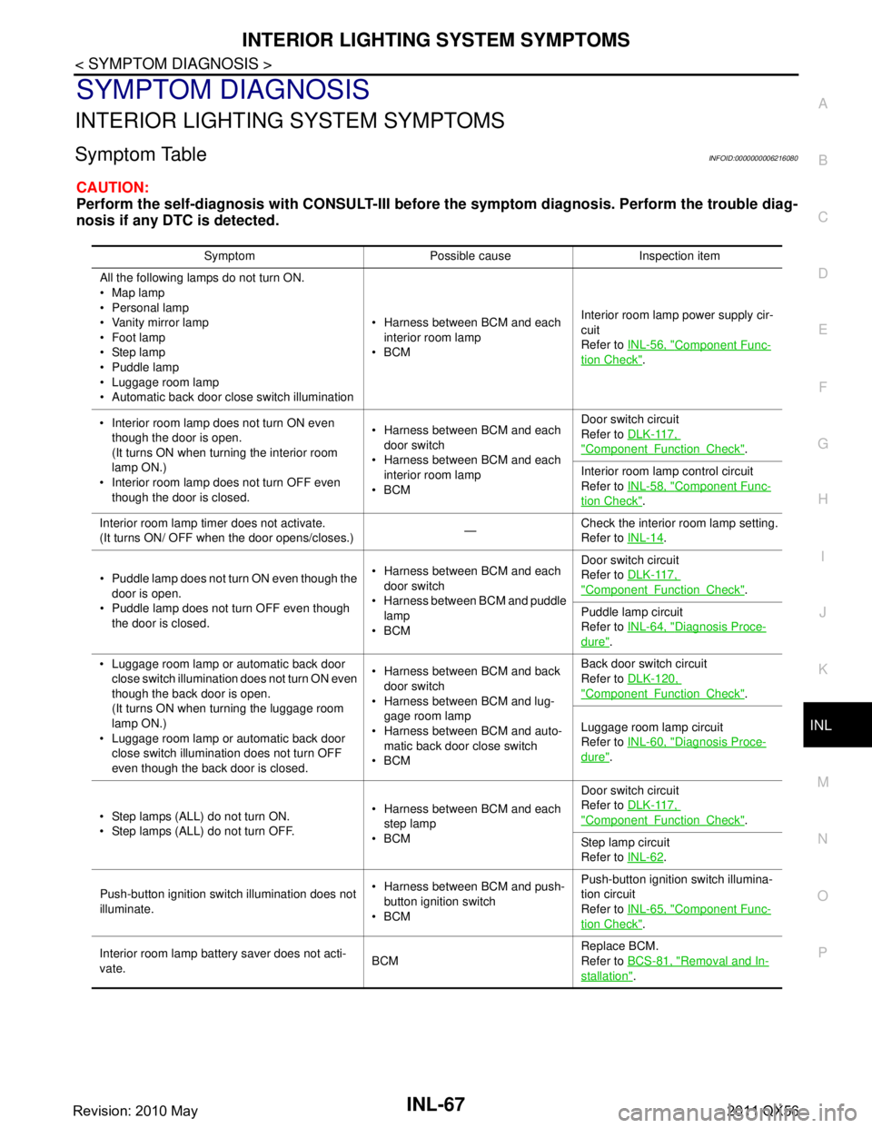
INTERIOR LIGHTING SYSTEM SYMPTOMS
Symptom TableINFOID:0000000006216080
CAUTION:
Perform the self-diagnosis with CONS ULT-III before the symptom diagnosis. Perform the trouble diag-
nosis if any DTC is detected.
Symptom Possible cause Inspection item
All the following lamps do not turn ON.
Map lamp
Personal lamp
Vanity mirror lamp
Foot lamp
Step lamp
Puddle lamp
Luggage room lamp
Automatic back door close switch illumination Harness between BCM and each
interior room lamp
BCM Interior room lamp
power supply cir-
cuit
Refer to INL-56, "
Component Func-
tion Check".
Interior room lamp does not turn ON even though the door is open.
(It turns ON when turning the interior room
lamp ON.)
Interior room lamp does not turn OFF even
though the door is closed. Harness between BCM and each
door switch
Harness between BCM and each
interior room lamp
BCM Door switch circuit
Refer to
DLK-117,
"ComponentFunctionCheck".
Interior room lamp control circuit
Refer to INL-58, "
Component Func-
tion Check".
Interior room lamp timer does not activate.
(It turns ON/ OFF when the door opens/closes.) —Check the interior room lamp setting.
Refer to
INL-14
.
Puddle lamp does not turn ON even though the door is open.
Puddle lamp does not turn OFF even though the door is closed. Harness between BCM and each
door switch
Harness between BCM and puddle lamp
BCM Door switch circuit
Refer to
DLK-117,
"ComponentFunctionCheck".
Puddle lamp circuit
Refer to INL-64, "
Diagnosis Proce-
dure".
Luggage room lamp or automatic back door close switch illumination does not turn ON even
though the back door is open.
(It turns ON when turning the luggage room
lamp ON.)
Luggage room lamp or automatic back door
close switch illumination does not turn OFF
even though the back door is closed. Harness between BCM and back
door switch
Harness between BCM and lug- gage room lamp
Harness between BCM and auto- matic back door close switch
BCM Back door switch circuit
Refer to
DLK-120,
"ComponentFunctionCheck".
Luggage room lamp circuit
Refer to INL-60, "
Diagnosis Proce-
dure".
Step lamps (ALL) do not turn ON.
Step lamps (ALL) do not turn OFF. Harness between BCM and each
step lamp
BCM Door switch circuit
Refer to
DLK-117,
"ComponentFunctionCheck".
Step lamp circuit
Refer to INL-62
.
Push-button ignition switch illumination does not
illuminate. Harness between BCM and push-
button ignition switch
BCM Push-button ignition switch illumina-
tion circuit
Refer to
INL-65, "
Component Func-
tion Check".
Interior room lamp battery saver does not acti-
vate. BCMReplace BCM.
Refer to
BCS-81, "
Removal and In-
stallation".
Revision: 2010 May2011 QX56
Page 3349 of 5598

INL-82
< SERVICE DATA AND SPECIFICATIONS (SDS)
SERVICE DATA AND SPECIFICATIONS (SDS)
SERVICE DATA AND SPECIFICATIONS (SDS)
SERVICE DATA AND SPECIFICATIONS (SDS)
Bulb SpecificationsINFOID:0000000006288670
Item Type Wattage (W)
Push-button ignition switch illumination LED —
Map lamp Wedge 8
Console lamp
(integrated into the map lamp assembly) LED —
Puddle lamp LED —
Vanity mirror lamp — 2
Glove box lamp Wedge 1.4
Foot lamp (driver and passenger) Wedge 1.4
Rear foot lamp LED —
Mood lamp (front and rear door armrest) LED —
Ste p lam p We dg e 8
Personal lamp Wedge 8
Luggage room lamp — 8
Revision: 2010 May2011 QX56
Page 3352 of 5598
PRECAUTIONSINT-3
< PRECAUTION >
C
DE
F
G H
I
K L
M A
B
INT
N
O P
PRECAUTION
PRECAUTIONS
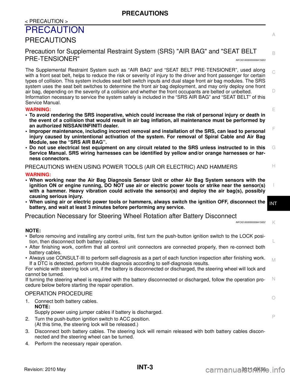
Precaution for Supplemental Restraint System (SRS) "AIR BAG" and "SEAT BELT
PRE-TENSIONER"
INFOID:0000000006415653
The Supplemental Restraint System such as “A IR BAG” and “SEAT BELT PRE-TENSIONER”, used along
with a front seat belt, helps to reduce the risk or severi ty of injury to the driver and front passenger for certain
types of collision. This system includes seat belt switch inputs and dual stage front air bag modules. The SRS
system uses the seat belt switches to determine the front air bag deployment, and may only deploy one front
air bag, depending on the severity of a collision and whether the front occupants are belted or unbelted.
Information necessary to service the system safely is included in the “SRS AIR BAG” and “SEAT BELT” of this
Service Manual.
WARNING:
• To avoid rendering the SRS inoper ative, which could increase the risk of personal injury or death in
the event of a collision that would result in air ba g inflation, all maintenance must be performed by
an authorized NISSAN/INFINITI dealer.
Improper maintenance, including in correct removal and installation of the SRS, can lead to personal
injury caused by unintentional act ivation of the system. For removal of Spiral Cable and Air Bag
Module, see the “SRS AIR BAG”.
Do not use electrical test equipm ent on any circuit related to the SRS unless instructed to in this
Service Manual. SRS wiring harnesses can be identi fied by yellow and/or orange harnesses or har-
ness connectors.
PRECAUTIONS WHEN USING POWER TOOLS (AIR OR ELECTRIC) AND HAMMERS
WARNING:
When working near the Air Bag Diagnosis Sensor Unit or other Air Bag System sensors with the
ignition ON or engine running, DO NOT use air or electric power tools or strike near the sensor(s)
with a hammer. Heavy vibration could activate the sensor(s) and deploy the air bag(s), possibly
causing serious injury.
When using air or electric power tools or hammers , always switch the ignition OFF, disconnect the
battery, and wait at least 3 minutes before performing any service.
Precaution Necessary for Steering Wh eel Rotation after Battery Disconnect
INFOID:0000000006415652
NOTE:
Before removing and installing any control units, first tu rn the push-button ignition switch to the LOCK posi-
tion, then disconnect both battery cables.
After finishing work, confirm that all control unit connectors are connected properly, then re-connect both
battery cables.
Always use CONSULT-III to perform self-diagnosis as a part of each function inspection after finishing work.
If a DTC is detected, perform trouble diagnos is according to self-diagnosis results.
For vehicle with steering lock unit, if the battery is disconnected or discharged, the steering wheel will lock and
cannot be turned.
If turning the steering wheel is required with the batte ry disconnected or discharged, follow the operation pro-
cedure below before starting the repair operation.
OPERATION PROCEDURE
1. Connect both battery cables. NOTE:
Supply power using jumper cables if battery is discharged.
2. Turn the push-button ignition switch to ACC position. (At this time, the steering lock will be released.)
3. Disconnect both battery cables. The steering lock wil l remain released with both battery cables discon-
nected and the steering wheel can be turned.
4. Perform the necessary repair operation.
Revision: 2010 May2011 QX56
Page 3353 of 5598
INT-4
< PRECAUTION >
PRECAUTIONS
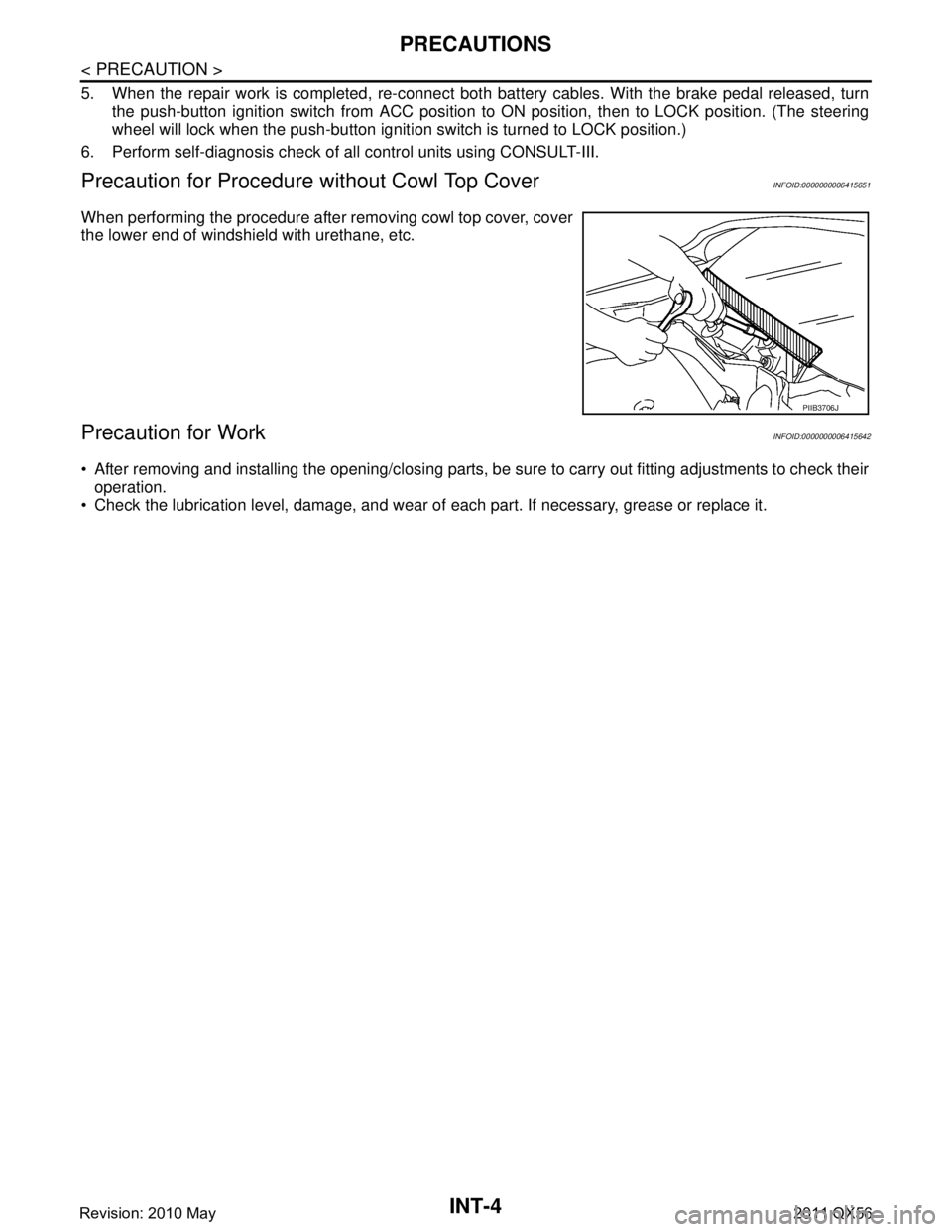
5. When the repair work is completed, re-connect both battery cables. With the brake pedal released, turn
the push-button ignition switch from ACC position to ON position, then to LOCK position. (The steering
wheel will lock when the push-button igniti on switch is turned to LOCK position.)
6. Perform self-diagnosis check of all control units using CONSULT-III.
Precaution for Procedure without Cowl Top CoverINFOID:0000000006415651
When performing the procedure after removing cowl top cover, cover
the lower end of windshield with urethane, etc.
Precaution for WorkINFOID:0000000006415642
After removing and installing the opening/closing parts, be sure to carry out fitting adjustments to check their
operation.
Check the lubrication level, damage, and wear of each part. If necessary, grease or replace it.
PIIB3706J
Revision: 2010 May2011 QX56
Page 3392 of 5598
IP-2
< PRECAUTION >
PRECAUTIONS
PRECAUTION
PRECAUTIONS
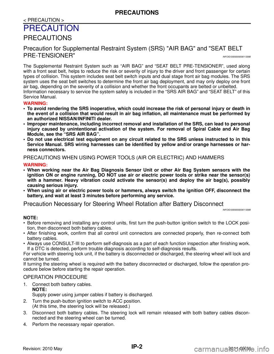
Precaution for Supplemental Restraint System (SRS) "AIR BAG" and "SEAT BELT
PRE-TENSIONER"
INFOID:0000000006113088
The Supplemental Restraint System such as “A IR BAG” and “SEAT BELT PRE-TENSIONER”, used along
with a front seat belt, helps to reduce the risk or severi ty of injury to the driver and front passenger for certain
types of collision. This system includes seat belt switch inputs and dual stage front air bag modules. The SRS
system uses the seat belt switches to determine the front air bag deployment, and may only deploy one front
air bag, depending on the severity of a collision and w hether the front occupants are belted or unbelted.
Information necessary to service the system safely is included in the “SRS AIR BAG” and “SEAT BELT” of this
Service Manual.
WARNING:
• To avoid rendering the SRS inopera tive, which could increase the risk of personal injury or death in
the event of a collision that would result in air bag inflation, all maintenance must be performed by
an authorized NISS AN/INFINITI dealer.
Improper maintenance, including in correct removal and installation of the SRS, can lead to personal
injury caused by unintent ional activation of the system. For re moval of Spiral Cable and Air Bag
Module, see the “SRS AIR BAG”.
Do not use electrical test equipmen t on any circuit related to the SRS unless instructed to in this
Service Manual. SRS wiring harnesses can be identi fied by yellow and/or orange harnesses or har-
ness connectors.
PRECAUTIONS WHEN USING POWER TOOLS (AIR OR ELECTRIC) AND HAMMERS
WARNING:
When working near the Air Bag Diagnosis Sensor Unit or other Air Bag System sensors with the ignition ON or engine running, DO NOT use air or electric power tools or strike near the sensor(s)
with a hammer. Heavy vibration could activate the sensor(s) and deploy the air bag(s), possibly
causing serious injury.
When using air or electric power tools or hammers , always switch the ignition OFF, disconnect the
battery, and wait at least 3 minu tes before performing any service.
Precaution Necessary for Steering W heel Rotation after Battery Disconnect
INFOID:0000000006113089
NOTE:
Before removing and installing any control units, first tu rn the push-button ignition switch to the LOCK posi-
tion, then disconnect bot h battery cables.
After finishing work, confirm that all control unit connectors are connected properly, then re-connect both
battery cables.
Always use CONSULT-III to perform self-diagnosis as a part of each function inspection after finishing work.
If a DTC is detected, perform trouble diagnos is according to self-diagnosis results.
For vehicle with steering lock unit, if the battery is disconnected or discharged, the steering wheel will lock and
cannot be turned.
If turning the steering wheel is required with the bat tery disconnected or discharged, follow the operation pro-
cedure below before starting the repair operation.
OPERATION PROCEDURE
1. Connect both battery cables. NOTE:
Supply power using jumper cables if battery is discharged.
2. Turn the push-button ignition switch to ACC position. (At this time, the steering lock will be released.)
3. Disconnect both battery cables. The steering lock wi ll remain released with both battery cables discon-
nected and the steering wheel can be turned.
4. Perform the necessary repair operation.
Revision: 2010 May2011 QX56
Page 3393 of 5598

PRECAUTIONSIP-3
< PRECAUTION >
C
DE
F
G H
I
K L
M A
B
IP
N
O P
5. When the repair work is completed, re-connect both battery cables. With the brake pedal released, turn
the push-button ignition switch from ACC position to ON position, then to LOCK position. (The steering
wheel will lock when the push-button ignition switch is turned to LOCK position.)
6. Perform self-diagnosis check of a ll control units using CONSULT-III.
ServiceINFOID:0000000006113090
Disconnect battery negative terminal in advance.
Disconnect air bag system line in advance.
Never tamper with or force air bag lid open, as this may adversely affect air bag performance.
Be careful not to scratch pad and other parts.
When removing or disassembling any part, be careful not to damage or deform it. Protect parts, that may get
in the way with a shop cloth.
When removing parts with a screwdriver or other tool, cover the tool surface with vinyl tape to protect parts.
Keep removed parts protected with a shop cloth.
If a clip is deformed or damaged, replace it.
If an unreusable part is removed, replace it with a new one.
Tighten bolts and nuts firmly to the specified torque.
After reassembly is complete, check that each part functions correctly.
Remove stains via the following procedure.
Water-soluble stains:
Dip a soft cloth in warm water, and then squeeze it tightly. After wiping off the stain, wipe with a soft dry cloth.
Oil stain:
Dissolve a synthetic detergent in warm water (density of 2 to 3%), dip the cloth, then wipe off the stain with the
cloth. Next, dip the cloth in fresh water and squeeze it tightly. Then wipe off the detergent completely. Then
wipe the area with a soft dry cloth.
Never use any organic solvent, such as thinner or benzine.
Revision: 2010 May2011 QX56
Page 3404 of 5598
IP-14
< REMOVAL AND INSTALLATION >
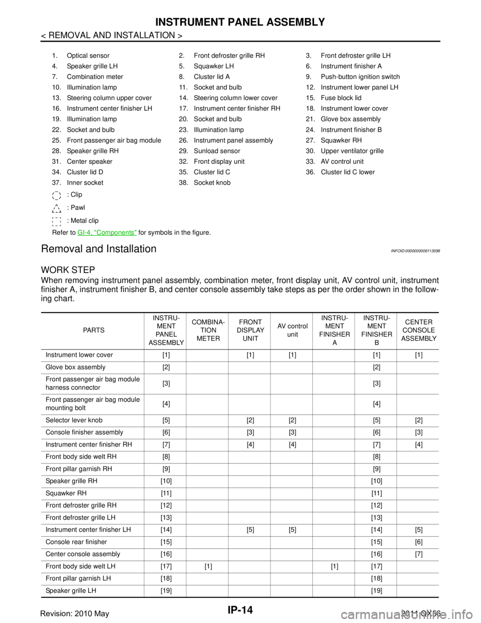
INSTRUMENT PANEL ASSEMBLY
Removal and Installation
INFOID:0000000006113098
WORK STEP
When removing instrument panel assembly, combination meter, front display unit, AV control unit, instrument
finisher A, instrument fini sher B, and center console assembly take st eps as per the order shown in the follow-
ing chart.
1. Optical sensor 2. Front defroster grille RH 3. Front defroster grille LH
4. Speaker grille LH 5. Squawker LH 6. Instrument finisher A
7. Combination meter 8. Cluster lid A 9. Push-button ignition switch
10. Illumination lamp 11. Socket and bulb 12. Instrument lower panel LH
13. Steering column upper cover 14. Steering column lower cover 15. Fuse block lid
16. Instrument center finisher LH 17. Instrument center finisher RH 18. Instrument lower cover
19. Illumination lamp 20. Socket and bulb 21. Glove box assembly
22. Socket and bulb 23. Illumination lamp 24. Instrument finisher B
25. Front passenger air bag module 26. Instrument panel assembly 27. Squawker RH
28. Speaker grille RH 29. Sunload sensor 30. Upper ventilator grille
31. Center speaker 32. Front display unit 33. AV control unit
34. Cluster lid D 35. Cluster lid C 36. Cluster lid C lower
37. Inner socket 38. Socket knob
: Clip
: Pawl
: Metal clip
Refer to GI-4, "
Components" for symbols in the figure.
PA R T S INSTRU-
MENT
PA N E L
ASSEMBLY COMBINA-
TION
METER FRONT
DISPLAY
UNIT AV c o n t r o l
unit INSTRU-
MENT
FINISHER A INSTRU-
MENT
FINISHER B CENTER
CONSOLE
ASSEMBLY
Instrument lower cover [1] [1] [1] [1] [1]
Glove box assembly [2] [2]
Front passenger air bag module
harness connector [3] [3]
Front passenger air bag module
mounting bolt [4] [4]
Selector lever knob [5] [2] [2] [5] [2]
Console finisher assembly [6] [3] [3] [6] [3]
Instrument center finisher RH [7] [4] [4] [7] [4]
Front body side welt RH [8] [8]
Front pillar garnish RH [9] [9]
Speaker grille RH [10] [10]
Squawker RH [11] [11]
Front defroster grille RH [12] [12]
Front defroster grille LH [13] [13]
Instrument center finisher LH [14] [5] [5] [14] [5]
Console rear finisher [15] [15] [6]
Center console assembly [16] [16] [7]
Front body side welt LH [17] [1] [1] [17]
Front pillar garnish LH [18] [18]
Speaker grille LH [19] [19]
Revision: 2010 May2011 QX56
Page 3427 of 5598
![INFINITI QX56 2011 Factory Service Manual
LAN
PRECAUTIONSLAN-7
< PRECAUTION > [CAN FUNDAMENTAL]
C
D
E
F
G H
I
J
K L
B A
O P
N
PRECAUTION
PRECAUTIONS
Precautions for Trouble DiagnosisINFOID:0000000006220510
CAUTION:
• Never apply 7.0 V or m INFINITI QX56 2011 Factory Service Manual
LAN
PRECAUTIONSLAN-7
< PRECAUTION > [CAN FUNDAMENTAL]
C
D
E
F
G H
I
J
K L
B A
O P
N
PRECAUTION
PRECAUTIONS
Precautions for Trouble DiagnosisINFOID:0000000006220510
CAUTION:
• Never apply 7.0 V or m](/manual-img/42/57033/w960_57033-3426.png)
LAN
PRECAUTIONSLAN-7
< PRECAUTION > [CAN FUNDAMENTAL]
C
D
E
F
G H
I
J
K L
B A
O P
N
PRECAUTION
PRECAUTIONS
Precautions for Trouble DiagnosisINFOID:0000000006220510
CAUTION:
• Never apply 7.0 V or more to the measurement terminal.
Use a tester with open terminal voltage of 7.0 V or less.
Turn the ignition switch OFF and disconnect th
e battery cable from the negative terminal when
checking the harness.
Precautions for Harness RepairINFOID:0000000006220511
• Solder the repaired area and wrap tape around the soldered area. NOTE:
A fray of twisted lines must be within 110 mm (4.33 in).
Bypass connection is never allowed at the repaired area. NOTE:
Bypass connection may cause CAN communication error. The
spliced wire becomes separated and t he characteristics of twisted
line are lost.
Replace the applicable harness as an assembly if error is detected on the shield lines of CAN communica-
tion line.
SKIB8766E
SKIB8767E
Revision: 2010 May2011 QX56