2011 INFINITI QX56 ignition
[x] Cancel search: ignitionPage 3244 of 5598
![INFINITI QX56 2011 Factory Service Manual
HAC-138
< SYMPTOM DIAGNOSIS >[AUTOMATIC AIR CONDITIONING]
INSUFFICIENT COOLING
INSUFFICIENT COOLING
FRONT AIR CONDITIONER
FRONT AIR CONDITIONER : DescriptionINFOID:0000000006275984
Symptom Insuffici INFINITI QX56 2011 Factory Service Manual
HAC-138
< SYMPTOM DIAGNOSIS >[AUTOMATIC AIR CONDITIONING]
INSUFFICIENT COOLING
INSUFFICIENT COOLING
FRONT AIR CONDITIONER
FRONT AIR CONDITIONER : DescriptionINFOID:0000000006275984
Symptom Insuffici](/manual-img/42/57033/w960_57033-3243.png)
HAC-138
< SYMPTOM DIAGNOSIS >[AUTOMATIC AIR CONDITIONING]
INSUFFICIENT COOLING
INSUFFICIENT COOLING
FRONT AIR CONDITIONER
FRONT AIR CONDITIONER : DescriptionINFOID:0000000006275984
Symptom Insufficient cooling
No cool air comes out. (Air flow volume is normal.)
FRONT AIR CONDITIONER
: Diagnosis ProcedureINFOID:0000000006275985
NOTE:
Perform self-diagnoses with CONSULT-III before perform ing symptom diagnosis. If any DTC is detected, per-
form the corresponding diagnosis.
1.CHECK MAGNET CLUTCH OPERATION
1. Turn ignition switch ON.
2. Operate fan switch.
3. Press A/C switch.
4. Check that A/C indicator turns ON. Check visually and by sound that compressor operates.
5. Press A/C switch again.
6. Check that A/C indicator turns OFF. Check that compressor stops.
Is the inspection result normal?
YES >> GO TO 2.
NO >> Perform diagnosis of “COMPRESSOR DOSE NOT OPERATE” in “SYMPTOM DIAGNOSIS”.
Refer to HAC-142, "
Diagnosis Procedure".
2.CHECK DRIVE BELT
Check tension of drive belt. Refer to EM-20, "
Checking".
Is the inspection result normal?
YES >> GO TO 3.
NO >> Adjust or replace drive belt depending on the inspection results.
3.CHECK REFRIGERANT CYCLE
Connect recovery/recycling recharging equipment to the vehicle and perform pressure inspection with gauge.
Refer to HA-27, "
Symptom Table".
Is the inspection result normal?
YES >> GO TO 4.
NO >> Repair or replace parts depending on the inspection results.
4.CHECK AIR LEAKAGE FROM EACH DUCT
Check duct and nozzle, etc. of the fr ont air conditioning system for leakage.
Is the inspection result normal?
YES >> GO TO 5.
NO >> Repair or replace parts depending on the inspection results.
5.CHECK AMBIENT TEMPERATURE DISPLAY
Check that there is not much diference between act ual ambient temperature and indicated temperature on
information display in combination meter.
Is the inspection result normal?
YES >> GO TO 6.
NO >> Perform diagnosis for the A/C auto amp. connection recognition signal circuit. Refer to MWI-74,
"DiagnosisProcedure".
6.CHECK SETTING OF TEMPERATURE SETTING TRIMMER (FRONT)
1. Check setting value of temperature setting trimmer (front). Refer to HAC-68, "
FRONT AUTOMATIC AIR
CONDITIONING SYSTEM : Temperature Setting Trimmer (Front)".
2. Check that temperature setting trimme r (front) is set to “+ direction”.
Revision: 2010 May2011 QX56
Page 3263 of 5598

HRN-2
< PRECAUTION >
PRECAUTIONS
PRECAUTION
PRECAUTIONS
Precaution for Supplemental Restraint System (SRS) "AIR BAG" and "SEAT BELT
PRE-TENSIONER"
INFOID:0000000006220273
The Supplemental Restraint System such as “A IR BAG” and “SEAT BELT PRE-TENSIONER”, used along
with a front seat belt, helps to reduce the risk or severi ty of injury to the driver and front passenger for certain
types of collision. This system includes seat belt switch inputs and dual stage front air bag modules. The SRS
system uses the seat belt switches to determine the front air bag deployment, and may only deploy one front
air bag, depending on the severity of a collision and w hether the front occupants are belted or unbelted.
Information necessary to service the system safely is included in the “SRS AIR BAG” and “SEAT BELT” of this
Service Manual.
WARNING:
• To avoid rendering the SRS inopera tive, which could increase the risk of personal injury or death in
the event of a collision that would result in air bag inflation, all maintenance must be performed by
an authorized NISS AN/INFINITI dealer.
Improper maintenance, including in correct removal and installation of the SRS, can lead to personal
injury caused by unintent ional activation of the system. For re moval of Spiral Cable and Air Bag
Module, see the “SRS AIR BAG”.
Do not use electrical test equipmen t on any circuit related to the SRS unless instructed to in this
Service Manual. SRS wiring harnesses can be identi fied by yellow and/or orange harnesses or har-
ness connectors.
PRECAUTIONS WHEN USING POWER TOOLS (AIR OR ELECTRIC) AND HAMMERS
WARNING:
When working near the Air Bag Diagnosis Sensor Unit or other Air Bag System sensors with the ignition ON or engine running, DO NOT use air or electric power tools or strike near the sensor(s)
with a hammer. Heavy vibration could activate the sensor(s) and deploy the air bag(s), possibly
causing serious injury.
When using air or electric power tools or hammers , always switch the ignition OFF, disconnect the
battery, and wait at least 3 minu tes before performing any service.
Revision: 2010 May2011 QX56
Page 3269 of 5598

INL-2
LUGGAGE ROOM LAMP CIRCUIT ..................60
Description ........................................................... ...60
Diagnosis Procedure ..............................................60
STEP LAMP CIRCUIT .......................................62
Description ........................................................... ...62
Component Function Check ...................................62
Diagnosis Procedure ..............................................62
PUDDLE LAMP CIRCUIT ..................................64
Description ........................................................... ...64
Diagnosis Procedure ..............................................64
PUSH-BUTTON IGNITION SWITCH ILLUMI-
NATION CIRCUIT ..............................................
65
Component Function Check ................................ ...65
Diagnosis Procedure ..............................................65
SYMPTOM DIAGNOSIS .............................67
INTERIOR LIGHTING SYSTEM SYMPTOMS ...67
Symptom Table ................................................... ...67
REMOVAL AND INSTALLATION ...............68
MAP LAMP ..................................................... ...68
Exploded View ..................................................... ...68
Removal and Installation ........................................68
Replacement ..........................................................68
VANITY MIRROR LAMP ...................................69
Exploded View ..................................................... ...69
Replacement ..........................................................69
GLOVE BOX LAMP ...........................................70
Exploded View ..................................................... ...70
Replacement ..........................................................70
FOOT LAMP ......................................................71
DRIVER SIDE ......................................................... ...71
DRIVER SIDE : Exploded View ..............................71
DRIVER SIDE : Replacement ................................71
PASSENGER SIDE ...................................................71
PASSENGER SIDE : Exploded View .....................71
PASSENGER SIDE : Replac ement ........................72
REAR FOOT LAMP ................................................ ...72
REAR FOOT LAMP : Exploded View .....................72
REAR FOOT LAMP : Removal and Installation ......72
STEP LAMP .......................................................74
Exploded View ..................................................... ...74
Removal and Installation .........................................74
Replacement ...........................................................74
MOOD LAMP .....................................................75
FRONT DOOR ARMREST ..................................... ...75
FRONT DOOR ARMREST : Exploded View ..........75
FRONT DOOR ARMREST : Replacement .............75
REAR DOOR ARMREST ....................................... ...75
REAR DOOR ARMREST : Exploded View .............75
REAR DOOR ARMREST : Replacement ...............76
PERSONAL LAMP ............................................77
Exploded View ..................................................... ...77
Removal and Installation .........................................77
Replacement ...........................................................78
PUDDLE LAMP .............................................. ...79
Exploded View ..................................................... ...79
Removal and Installation .........................................79
LUGGAGE ROOM LAMP ..................................81
Exploded View ..................................................... ...81
Removal and Installation .........................................81
Replacement ...........................................................81
SERVICE DATA AND SPECIFICATIONS
(SDS) .......... ................................................
82
SERVICE DATA AND SPECIFICATIONS
(SDS) .............................................................. ...
82
Bulb Specifications ............................................... ...82
Revision: 2010 May2011 QX56
Page 3270 of 5598

PRECAUTIONSINL-3
< PRECAUTION >
C
DE
F
G H
I
J
K
M A
B
INL
N
O P
PRECAUTION
PRECAUTIONS
Precaution for Supplemental Restraint System (SRS) "AIR BAG" and "SEAT BELT
PRE-TENSIONER"
INFOID:0000000006377028
The Supplemental Restraint System such as “A IR BAG” and “SEAT BELT PRE-TENSIONER”, used along
with a front seat belt, helps to reduce the risk or severi ty of injury to the driver and front passenger for certain
types of collision. This system includes seat belt switch inputs and dual stage front air bag modules. The SRS
system uses the seat belt switches to determine the front air bag deployment, and may only deploy one front
air bag, depending on the severity of a collision and whether the front occupants are belted or unbelted.
Information necessary to service the system safely is included in the “SRS AIR BAG” and “SEAT BELT” of this
Service Manual.
WARNING:
• To avoid rendering the SRS inoper ative, which could increase the risk of personal injury or death in
the event of a collision that would result in air ba g inflation, all maintenance must be performed by
an authorized NISSAN/INFINITI dealer.
Improper maintenance, including in correct removal and installation of the SRS, can lead to personal
injury caused by unintentional act ivation of the system. For removal of Spiral Cable and Air Bag
Module, see the “SRS AIR BAG”.
Do not use electrical test equipm ent on any circuit related to the SRS unless instructed to in this
Service Manual. SRS wiring harnesses can be identi fied by yellow and/or orange harnesses or har-
ness connectors.
PRECAUTIONS WHEN USING POWER TOOLS (AIR OR ELECTRIC) AND HAMMERS
WARNING:
When working near the Air Bag Diagnosis Sensor Unit or other Air Bag System sensors with the
ignition ON or engine running, DO NOT use air or electric power tools or strike near the sensor(s)
with a hammer. Heavy vibration could activate the sensor(s) and deploy the air bag(s), possibly
causing serious injury.
When using air or electric power tools or hammers , always switch the ignition OFF, disconnect the
battery, and wait at least 3 minutes before performing any service.
Revision: 2010 May2011 QX56
Page 3271 of 5598

INL-4
< SYSTEM DESCRIPTION >
COMPONENT PARTS
SYSTEM DESCRIPTION
COMPONENT PARTS
Component Parts LocationINFOID:0000000006216048
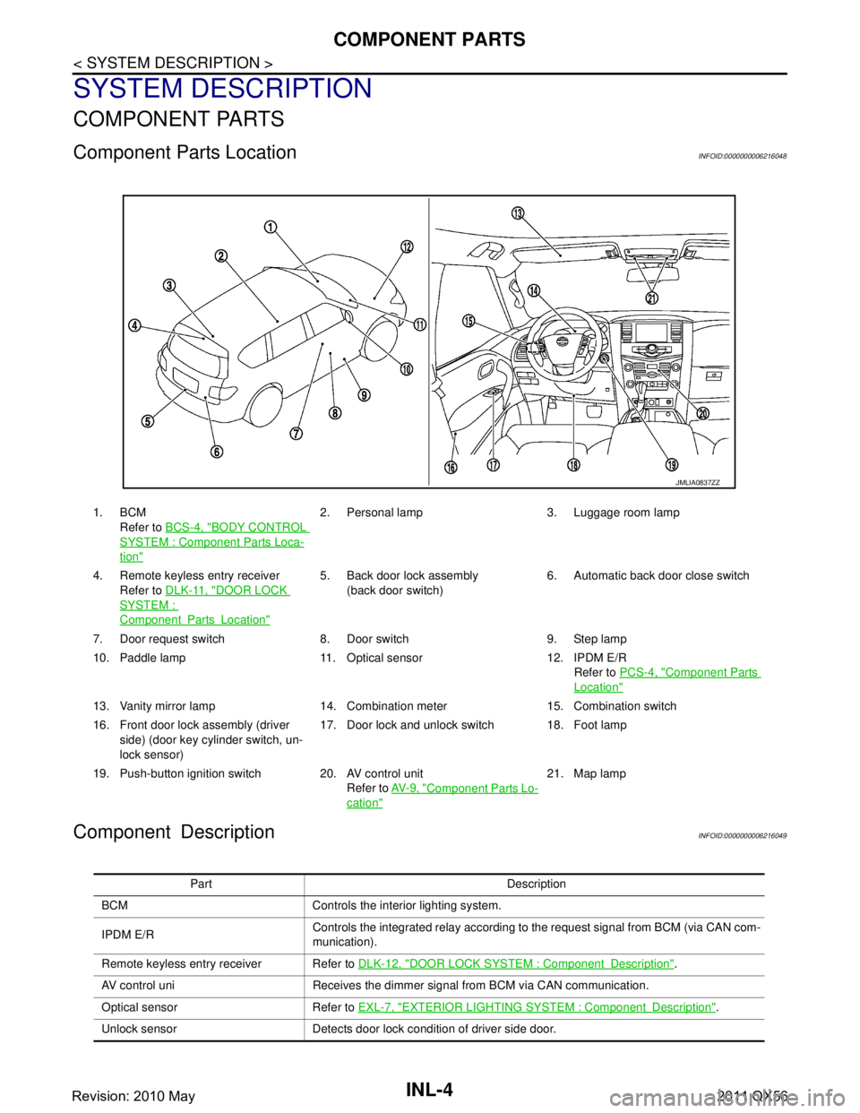
Component DescriptionINFOID:0000000006216049
1. BCMRefer to BCS-4, "
BODY CONTROL
SYSTEM : Componen t Parts Loca-
tion"
2. Personal lamp 3. Luggage room lamp
4. Remote keyless entry receiver Refer to DLK-11, "
DOOR LOCK
SYSTEM :
ComponentPartsLocation"
5. Back door lock assembly
(back door switch) 6. Automatic back door close switch
7. Door request switch 8. Door switch 9. Step lamp
10. Paddle lamp 11. Optical sensor 12. IPDM E/R Refer to PCS-4, "
Component Parts
Location"
13. Vanity mirror lamp 14. Combination meter 15. Combination switch
16. Front door lock assembly (driver
side) (door key cylinder switch, un-
lock sensor) 17. Door lock and unlock switch 18. Foot lamp
19. Push-button ignition switch 20. AV control unit Refer to AV- 9 , "
Component Parts Lo-
cation"
21. Map lamp
JMLIA0837ZZ
Part Description
BCM Controls the interior lighting system.
IPDM E/R Controls the integrated relay according to the request signal from BCM (via CAN com-
munication).
Remote keyless entry receiver Refer to DLK-12, "
DOOR LOCK SYSTEM : ComponentDescription".
AV control uni Receives the dimmer signal from BCM via CAN communication.
Optical sensor Refer to EXL-7, "
EXTERIOR LIGHTING SYSTEM : ComponentDescription".
Unlock sensor Detects door lock condition of driver side door.
Revision: 2010 May2011 QX56
Page 3273 of 5598

INL-6
< SYSTEM DESCRIPTION >
SYSTEM
SYSTEM
INTERIOR ROOM LAMP CONTROL SYSTEM
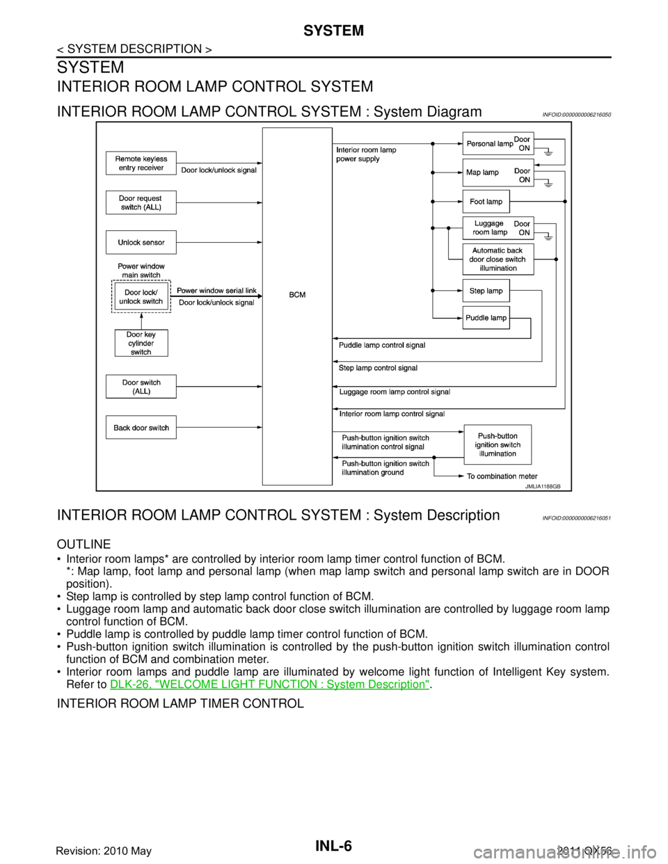
INTERIOR ROOM LAMP CONTROL SYSTEM : System DiagramINFOID:0000000006216050
INTERIOR ROOM LAMP CONTROL SYSTEM : System DescriptionINFOID:0000000006216051
OUTLINE
Interior room lamps* are controlled by interi or room lamp timer control function of BCM.
*: Map lamp, foot lamp and personal lamp (when map lamp switch and personal lamp switch are in DOOR
position).
Step lamp is controlled by step lamp control function of BCM.
Luggage room lamp and automatic back door close switch illumination are controlled by luggage room lamp
control function of BCM.
Puddle lamp is controlled by puddle lamp timer control function of BCM.
Push-button ignition switch illumination is controlled by the push-button ignition switch illumination control
function of BCM and combination meter.
Interior room lamps and puddle lamp are illuminated by welcome light function of Intelligent Key system.
Refer to DLK-26, "
WELCOME LIGHT FUNCTION : System Description".
INTERIOR ROOM LAMP TIMER CONTROL
JMLIA1188GB
Revision: 2010 May2011 QX56
Page 3274 of 5598

SYSTEMINL-7
< SYSTEM DESCRIPTION >
C
DE
F
G H
I
J
K
M A
B
INL
N
O P
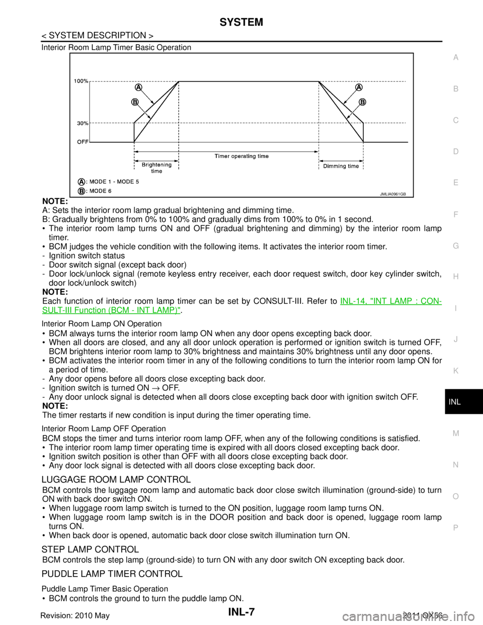
Interior Room Lamp Timer Basic Operation
NOTE:
A: Sets the interior room lamp gradual brightening and dimming time.
B: Gradually brightens from 0% to 100% and gradually dims from 100% to 0% in 1 second.
The interior room lamp turns ON and OFF (gradual brightening and dimming) by the interior room lamp
timer.
BCM judges the vehicle condition with the following items. It activates the interior room timer.
- Ignition switch status
- Door switch signal (except back door)
- Door lock/unlock signal (remote keyless entry receiv er, each door request switch, door key cylinder switch,
door lock/unlock switch)
NOTE:
Each function of interior room lamp ti mer can be set by CONSULT-III. Refer to INL-14, "
INT LAMP : CON-
SULT-III Function (BCM - INT LAMP)".
Interior Room Lamp ON Operation
BCM always turns the interior room lamp ON when any door opens excepting back door.
When all doors are closed, and any all door unlock operation is performed or ignition switch is turned OFF,
BCM brightens interior room lamp to 30% bri ghtness and maintains 30% brightness until any door opens.
BCM activates the interior room timer in any of the fo llowing conditions to turn the interior room lamp ON for
a period of time.
- Any door opens before all doors close excepting back door.
- Ignition switch is turned ON → OFF.
- Any door unlock signal is detected when all doors cl ose excepting back door with ignition switch OFF.
NOTE:
The timer restarts if new condition is input during the timer operating time.
Interior Room Lamp OFF Operation
BCM stops the timer and turns interior room lamp OF F, when any of the following conditions is satisfied.
The interior room lamp timer operating time is expired with all doors closed excepting back door.
Ignition switch position is other than O FF with all doors close excepting back door.
Any door lock signal is detected with all doors close excepting back door.
LUGGAGE ROOM LAMP CONTROL
BCM controls the luggage room lamp and automatic back door close switch illumination (ground-side) to turn
ON with back door switch ON.
When luggage room lamp switch is turned to the ON position, luggage room lamp turns ON.
When luggage room lamp switch is in the DOOR position and back door is opened, luggage room lamp turns ON.
When back door is opened, automatic back door close switch illumination turn ON.
STEP LAMP CONTROL
BCM controls the step lamp (ground-side) to turn ON with any door switch ON excepting back door.
PUDDLE LAMP TIMER CONTROL
Puddle Lamp Timer Basic Operation
BCM controls the ground to turn the puddle lamp ON.
JMLIA0961GB
Revision: 2010 May2011 QX56
Page 3275 of 5598

INL-8
< SYSTEM DESCRIPTION >
SYSTEM
The puddle lamp turns ON and OFF by the puddle lamp timer.
BCM judges the vehicle condition with the following items. It activates the puddle lamp timer.
- Ignition switch status
- Door switch signal (except back door)
- Door lock/unlock signal (remote keyless entry receiver, each door request switch)
- Driver side door lock status
Puddle Lamp ON Operation
BCM activates the puddle lamp timer in any of the following conditions to turn the puddle lamp ON for a period
of time.
Any door opens excepting back door.
Any door opens before all doors close excepting back door.
Ignition switch is turned ON → OFF.
Door unlock signal by remote keyless entry rece iver or each door request switch is detected.
Driver side door is locked*.
NOTE:
The timer restarts if new condition is input during the timer operating time.
Puddle Lamp OFF Operation
BCM stops the timer and turns puddle lamp OFF, when any of the following conditions are satisfied.
The puddle lamp timer operating time is expired.
The interior room lamp OFF conditions.
The interior room lamp timer operating time is expired.
PUSH-BUTTON IGNITION SWITCH ILLUMINATION CONTROL
Push-button Ignition Switch Illumination Basic Operation
BCM controls the ON/OFF status of push-button igni tion switch illumination according to vehicle status.
BCM provides the push-button ignition switch illumi nation control signal and the ground to turn the push-but-
ton ignition switch illumination ON.
BCM cuts the ground supply while each illumination (tai l lamp) is ON. BCM switches to the ground control
according to the meter illumination control function. Refer to MWI-16, "
METER ILLUMINATION CONTROL :
System Description".
Heart Beat Operation
BCM repeats brightening and dimming operation of push-button ignition switch illumination when any of the
following conditions are satisfied.
Welcome light function operates.
When ignition switch is OFF and any of the following conditions are satisfied.
- Driver side door changes from closed to open
- Driver side door changes from locked to unlocked
- Intelligent Key ID comparison is OK and driver side door changes from open to closed
- ID comparison by Intelligent Key transponder is OK
Illumination ON Operation
When ignition switch is not OFF or tail lamp turns ON, push-button ignition switch illumination turns ON.
Dimming Operation
When tail lamp turns OFF and ignition switch is turned OFF, push-button ignition switch illumination dims to
50% brightness.
Illumination OFF Operation
Push-button ignition switch illumination turns OFF when ignition switch turns OFF and tail lamp turns from ON
to OFF, while push-button ignition switch illumination is in ON status.
When push-button ignition switch illumination is at 50% brightness or in heartbeat status, and any of the fol-
lowing conditions are satisfied, push-butt on ignition switch illumination turns OFF.
15 seconds after start of heartbeat operation.
When welcome light function is not operating and any on the following conditions is satisfied.
- Driver side door is closed
- Driver side door is locked
- Intelligent Key ID comparison is NG
- Comparison of Intelligent Key ID by transponder is NG
INTERIOR ROOM LAMP BATTERY SAVER SYSTEM
Revision: 2010 May2011 QX56