2011 INFINITI QX56 change time
[x] Cancel search: change timePage 5213 of 5598
![INFINITI QX56 2011 Factory Service Manual
P0734 4GR INCORRECT RATIOTM-125
< DTC/CIRCUIT DIAGNOSIS > [7AT: RE7R01B]
C
EF
G H
I
J
K L
M A
B
TM
N
O P
3. Keep the current driving status for 2 seconds or more if CONSULT-III screen changes from � INFINITI QX56 2011 Factory Service Manual
P0734 4GR INCORRECT RATIOTM-125
< DTC/CIRCUIT DIAGNOSIS > [7AT: RE7R01B]
C
EF
G H
I
J
K L
M A
B
TM
N
O P
3. Keep the current driving status for 2 seconds or more if CONSULT-III screen changes from �](/manual-img/42/57033/w960_57033-5212.png)
P0734 4GR INCORRECT RATIOTM-125
< DTC/CIRCUIT DIAGNOSIS > [7AT: RE7R01B]
C
EF
G H
I
J
K L
M A
B
TM
N
O P
3. Keep the current driving status for 2 seconds or more if CONSULT-III screen changes from “OUT OF
CONDITION” to “TESTING”.
CAUTION:
When “TESTING” is not indicated on CONSULT-III for a long time, check “Self Diagnostic Results”
in “TRANSMISSION”. When a DTC other than “P0734” is detected, check the DTC. Refer to TM-78,
"DTC Index".
With GST
1. Drive vehicle and maintain the following conditions for 2 seconds or more.
2. Check DTC.
Is
“OUT OF CONDITION”, “STOP VEHICLE” or “COMPLETED RESULT NG” displayed? / Is “P0734”
detected?
YES-1 (OUT OF CONDITION) >>Perform “Step 3” again.
YES-2 (STOP VEHICLE)>>GO TO 4.
YES-3 (COMPLETED RESULT NG)>>Go to TM-125, "
Diagnosis Procedure".
YES-4 (“P0734” is detected)>>Go to TM-125, "
Diagnosis Procedure".
NO >> GO TO 4.
4.CHECK SYMPTOM (PART 2)
1. Stop vehicle.
2. Drive vehicle in “D” position allowing it to shift from 1GR to 7GR and check shift timing and shift shock.
>> INSPECTION END
Diagnosis ProcedureINFOID:0000000006226832
1.DETECT MALFUNCTIONING ITEM
Disassemble the A/T assembly to check component parts. Refer to TM-226, "
Disassembly".
NOTE:
Check the component parts, referring to “Possibl e cause” in “DTC DETECTION LOGIC”. Refer to TM-124,
"DTC Logic".
Is the inspection result normal?
YES >> Replace the transmission case and control valve & TCM. Refer to TM-211, "Exploded View".
NO >> Repair or replace damaged parts.
GEAR : 4th
ACCELE POSI : 0.7/8 or more
VEHICLE SPEED : 10 km/h (7 MPH) or more
Selector lever : “M” position
Gear position : 4th
Accelerator pedal opening : 0.7/8 or more
Vehicle speed : 10 km/h (7 MPH) or more
Revision: 2010 May2011 QX56
Page 5215 of 5598
![INFINITI QX56 2011 Factory Service Manual
P0735 5GR INCORRECT RATIOTM-127
< DTC/CIRCUIT DIAGNOSIS > [7AT: RE7R01B]
C
EF
G H
I
J
K L
M A
B
TM
N
O P
3. Keep the current driving status for 2 seconds or more if CONSULT-III screen changes from � INFINITI QX56 2011 Factory Service Manual
P0735 5GR INCORRECT RATIOTM-127
< DTC/CIRCUIT DIAGNOSIS > [7AT: RE7R01B]
C
EF
G H
I
J
K L
M A
B
TM
N
O P
3. Keep the current driving status for 2 seconds or more if CONSULT-III screen changes from �](/manual-img/42/57033/w960_57033-5214.png)
P0735 5GR INCORRECT RATIOTM-127
< DTC/CIRCUIT DIAGNOSIS > [7AT: RE7R01B]
C
EF
G H
I
J
K L
M A
B
TM
N
O P
3. Keep the current driving status for 2 seconds or more if CONSULT-III screen changes from “OUT OF
CONDITION” to “TESTING”.
CAUTION:
When “TESTING” is not indicated on CONSULT-III for a long time, check “Self Diagnostic Results”
in “TRANSMISSION”. When a DTC other than “P0735” is detected, check the DTC. Refer to TM-78,
"DTC Index".
With GST
1. Drive vehicle and maintain the following conditions for 2 seconds or more.
2. Check DTC.
Is
“OUT OF CONDITION”, “STOP VEHICLE” or “COMPLETED RESULT NG” displayed? / Is “P0735”
detected?
YES-1 (OUT OF CONDITION) >>Perform “Step 3” again.
YES-2 (STOP VEHICLE)>>GO TO 4.
YES-3 (COMPLETED RESULT NG)>>Go to TM-127, "
Diagnosis Procedure".
YES-4 (“P0735” is detected)>>Go to TM-127, "
Diagnosis Procedure".
NO >> GO TO 4.
4.CHECK SYMPTOM (PART 2)
1. Stop vehicle.
2. Drive vehicle in “D” position allowing it to shift from 1GR to 7GR and check shift timing and shift shock.
>> INSPECTION END
Diagnosis ProcedureINFOID:0000000006226835
1.DETECT MALFUNCTIONING ITEM
Disassemble the A/T assembly to check component parts. Refer to TM-226, "
Disassembly".
NOTE:
Check the component parts, referring to “Possibl e cause” in “DTC DETECTION LOGIC”. Refer to TM-126,
"DTC Logic".
Is the inspection result normal?
YES >> Replace the control valve & TCM. Refer to TM-182, "Exploded View".
NO >> Repair or replace damaged parts.
GEAR : 5th
ACCELE POSI : 0.7/8 or more
VEHICLE SPEED : 10 km/h (7 MPH) or more
Selector lever : “M” position
Gear position : 5th
Accelerator pedal opening : 0.7/8 or more
Vehicle speed : 10 km/h (7 MPH) or more
Revision: 2010 May2011 QX56
Page 5231 of 5598
![INFINITI QX56 2011 Factory Service Manual
P1734 7GR INCORRECT RATIOTM-143
< DTC/CIRCUIT DIAGNOSIS > [7AT: RE7R01B]
C
EF
G H
I
J
K L
M A
B
TM
N
O P
3. Keep the current driving status for 2 seconds or more if CONSULT-III screen changes from � INFINITI QX56 2011 Factory Service Manual
P1734 7GR INCORRECT RATIOTM-143
< DTC/CIRCUIT DIAGNOSIS > [7AT: RE7R01B]
C
EF
G H
I
J
K L
M A
B
TM
N
O P
3. Keep the current driving status for 2 seconds or more if CONSULT-III screen changes from �](/manual-img/42/57033/w960_57033-5230.png)
P1734 7GR INCORRECT RATIOTM-143
< DTC/CIRCUIT DIAGNOSIS > [7AT: RE7R01B]
C
EF
G H
I
J
K L
M A
B
TM
N
O P
3. Keep the current driving status for 2 seconds or more if CONSULT-III screen changes from “OUT OF
CONDITION” to “TESTING”.
CAUTION:
When “TESTING” is not indicated on CONSULT-III for a long time, check “Self Diagnostic Results”
in “TRANSMISSION”. When a DTC other than “P1734” is detected, check the DTC. Refer to TM-78,
"DTC Index".
With GST
1. Drive vehicle and maintain the following conditions for 2 seconds or more.
2. Check DTC.
Is
“OUT OF CONDITION”, “STOP VEHICLE” or “COMPLETED RESULT NG” displayed? / Is “P1734”
detected?
YES-1 (OUT OF CONDITION) >>Perform “Step 3” again.
YES-2 (STOP VEHICLE)>>GO TO 4.
YES-3 (COMPLETED RESULT NG)>>Go to TM-143, "
Diagnosis Procedure".
YES-4 (“P1734” is detected)>>Go to TM-143, "
Diagnosis Procedure".
NO >> GO TO 4.
4.CHECK SYMPTOM (PART 2)
With CONSULT-III
1. Stop vehicle.
2. Drive vehicle in “D” position allowing it to shift from 1GR to 7GR and check shift timing and shift shock.
>> INSPECTION END
Diagnosis ProcedureINFOID:0000000006226863
1.DETECT MALFUNCTIONING ITEM
Disassemble the A/T assembly to check component parts. Refer to TM-226, "
Disassembly".
NOTE:
Check the component parts, referring to “Possibl e cause” in “DTC DETECTION LOGIC”. Refer to TM-142,
"DTC Logic".
Is the inspection result normal?
YES >> Replace the control valve & TCM. Refer to TM-182, "Exploded View".
NO >> Repair or replace damaged parts.
GEAR : 7th
ACCELE POSI : 0.7/8 or more
VEHICLE SPEED : 10 km/h (7 MPH) or more
Selector lever : “M” position
Gear position : 7th
Accelerator pedal opening : 0.7/8 or more
Vehicle speed : 10 km/h (7 MPH) or more
Revision: 2010 May2011 QX56
Page 5411 of 5598

WCS
SYSTEMWCS-7
< SYSTEM DESCRIPTION >
C
DE
F
G H
I
J
K L
M B A
O P
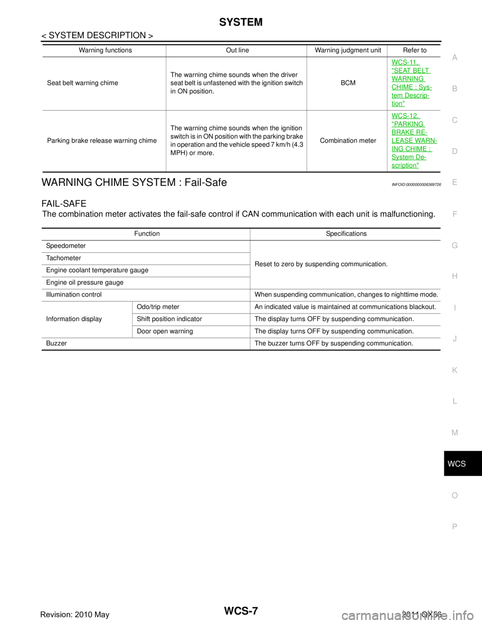
WARNING CHIME SYSTEM : Fail-SafeINFOID:0000000006369726
FA I L - S A F E
The combination meter activates the fail-safe contro l if CAN communication with each unit is malfunctioning.
Seat belt warning chimeThe warning chime sounds when the driver
seat belt is unfastened with the ignition switch
in ON position. BCMWCS-11,
"SEAT BELT
WARNING
CHIME : Sys-
tem Descrip-
tion"
Parking brake release warning chime
The warning chime sounds when the ignition
switch is in ON position with the parking brake
in operation and the vehicle speed 7 km/h (4.3
MPH) or more. Combination meterWCS-12,
"PA R K I N G
BRAKE RE-
LEASE WARN-
ING CHIME :
System De-
scription"
Warning functions Out line Warning judgment unit Refer to
Function Specifications
Speedometer
Reset to zero by suspending communication.
Tachometer
Engine coolant temperature gauge
Engine oil pressure gauge
Illumination control When suspending communication, changes to nighttime mode.
Information display Odo/trip meter An indicated value is maintained at communications blackout.
Shift position indicator The display turns OFF by suspending communication.
Door open warning The display turns OFF by suspending communication.
Buzzer The buzzer turns OFF by suspending communication.
Revision: 2010 May2011 QX56
Page 5423 of 5598

WCS
DIAGNOSIS SYSTEM (BCM)WCS-19
< SYSTEM DESCRIPTION >
C
DE
F
G H
I
J
K L
M B A
O P
DIAGNOSIS SYSTEM (BCM)
COMMON ITEM
COMMON ITEM : CONSULT-III Fu nction (BCM - COMMON ITEM)INFOID:0000000006419721
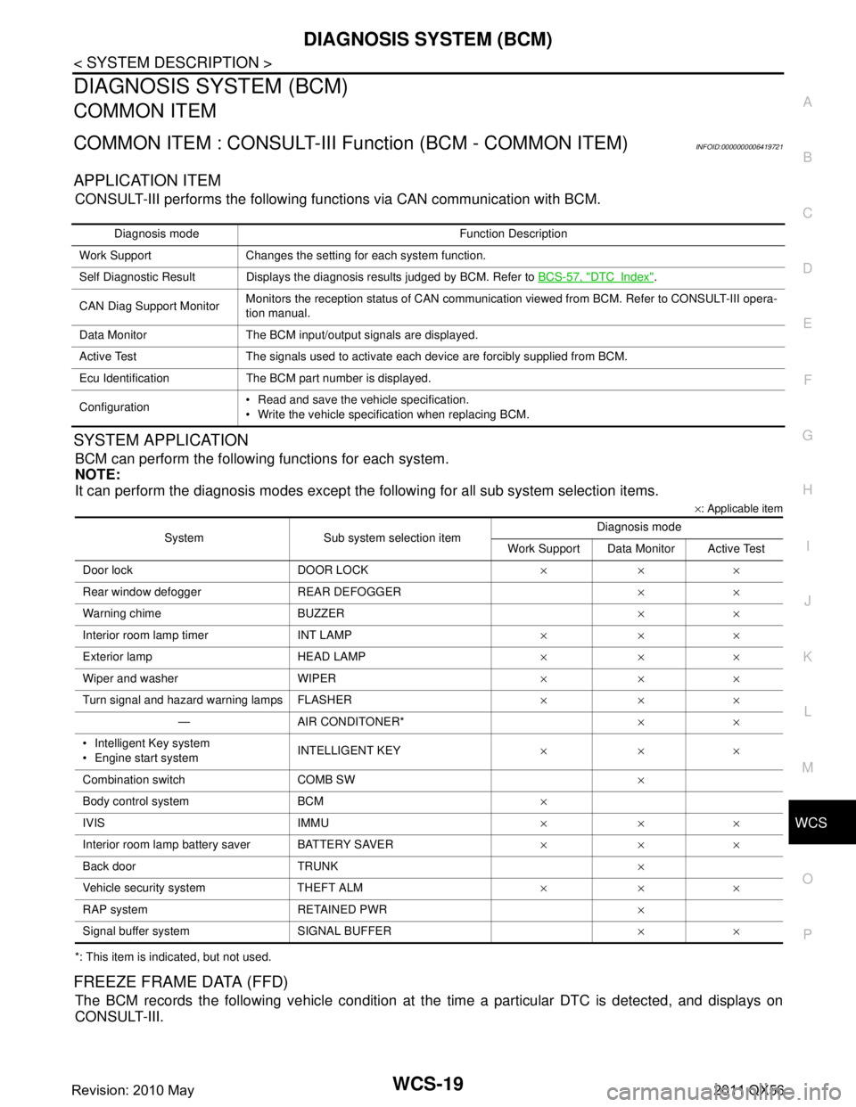
APPLICATION ITEM
CONSULT-III performs the following functions via CAN communication with BCM.
SYSTEM APPLICATION
BCM can perform the following functions for each system.
NOTE:
It can perform the diagnosis modes except the following for all sub system selection items.
×: Applicable item
*: This item is indicated, but not used.
FREEZE FRAME DATA (FFD)
The BCM records the following vehicle condition at the time a particular DTC is detected, and displays on
CONSULT-III.
Diagnosis mode Function Description
Work Support Changes the setting for each system function.
Self Diagnostic Result Displays the diagnosis results judged by BCM. Refer to BCS-57, "
DTCIndex".
CAN Diag Support Monitor Monitors the reception status of CAN communication viewed from BCM. Refer to CONSULT-III opera-
tion manual.
Data Monitor The BCM input/output signals are displayed.
Active Test The signals used to activate each device are forcibly supplied from BCM.
Ecu Identification The BCM part number is displayed.
Configuration Read and save the vehicle specification.
Write the vehicle specification when replacing BCM.
System Sub system selection item Diagnosis mode
Work Support Data Monitor Active Test
Door lock DOOR LOCK ×××
Rear window defo gger REAR DEFOGGER ××
Warning chime BUZZER ××
Interior room lamp timer INT LAMP ×××
Exterior lamp HEAD LAMP ×××
Wiper and washer WIPER ×××
Turn signal and hazard warning lamps FLASHER ×××
— AIR CONDITONER* ××
Intelligent Key system
Engine start system INTELLIGENT KEY
×××
Combination switch COMB SW ×
Body control system BCM ×
IVIS IMMU ×××
Interior room lamp battery saver BATTERY SAVER ×××
Back door TRUNK ×
Vehicle security system THEFT ALM ×××
RAP system RETAINED PWR ×
Signal buffer system SIGNAL BUFFER ××
Revision: 2010 May2011 QX56
Page 5433 of 5598

WCS
COMBINATION METERWCS-29
< ECU DIAGNOSIS INFORMATION >
C
DE
F
G H
I
J
K L
M B A
O P
Fail-SafeINFOID:0000000006222689
FA I L - S A F E
The combination meter activates the fail-safe contro l if CAN communication with each unit is malfunctioning.
37
(R/Y) Ground Non-manual mode signal Input Ignition
switch
ONSelector manual mode po-
sition
12 V
Other than the above 0 V
38
(L/W) Ground Manual mode shift down
signal InputIgnition
switch
ON Selector lever DOWN oper-
ation
0 V
Other than the above 12 V
39
(Y/B) Ground Manual mode shift up sig-
nal InputIgnition
switch
ON Selector lever UP operation 0 V
Other than the above 12 V
40
(G/W) Ground Manual mode signal Input Ignition
switch
ONSelector manual mode po-
sition
0 V
Other than the above 12 V
Te r m i n a l N o .
(Wire color) Description
ConditionVa l u e
(Approx.)
+ – Signal name Input/
Output
Function Specifications
Speedometer
Reset to zero by suspending communication.
Tachometer
Engine coolant temperature gauge
Engine oil pressure gauge
Illumination control When suspending communication, changes to nighttime mode.
Information display Odo/trip meter An indicated value is maintained at communications blackout.
Shift position indicator The display turns OFF by suspending communication.
Door open warning The display turns OFF by suspending communication.
Buzzer The buzzer turns OFF by suspending communication.
Revision: 2010 May2011 QX56
Page 5497 of 5598

C1755, C1756, C1757, C1758 POOR RECEIVING CONDITIONS
WT-47
< DTC/CIRCUIT DIAGNOSIS >
C
DF
G H
I
J
K L
M A
B
WT
N
O P
C1755, C1756, C1757, C1758 PO OR RECEIVING CONDITIONS
DTC LogicINFOID:0000000006225522
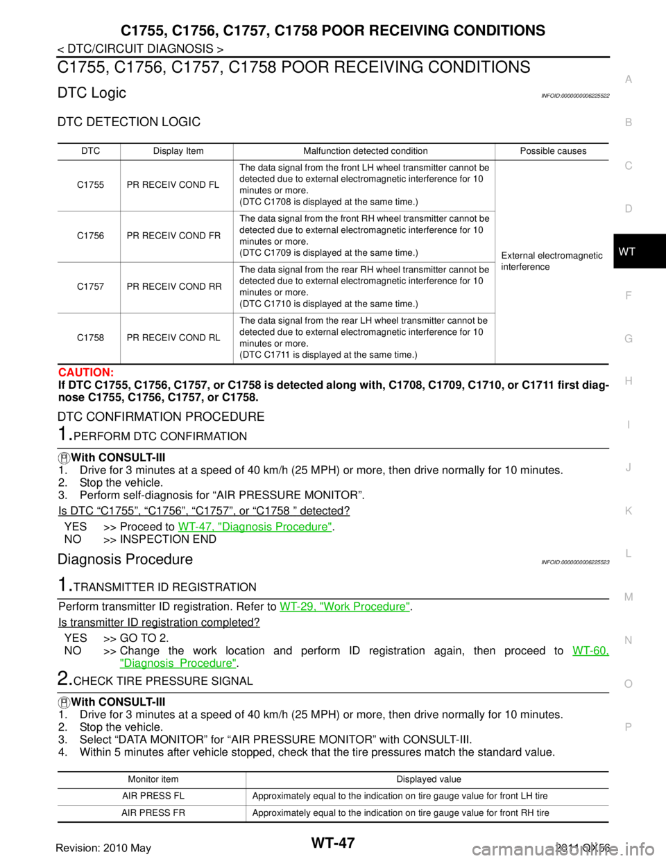
DTC DETECTION LOGIC
CAUTION:
If DTC C1755, C1756, C1757, or C1758 is detected al ong with, C1708, C1709, C1710, or C1711 first diag-
nose C1755, C1756, C1757, or C1758.
DTC CONFIRMATION PROCEDURE
1.PERFORM DTC CONFIRMATION
With CONSULT-III
1. Drive for 3 minutes at a speed of 40 km/h (25 MPH) or more, then drive normally for 10 minutes.
2. Stop the vehicle.
3. Perform self-diagnosis for “AIR PRESSURE MONITOR”.
Is DTC
“C1755”, “C1756”, “C1757”, or “C1758 ” detected?
YES >> Proceed to WT-47, "Diagnosis Procedure".
NO >> INSPECTION END
Diagnosis ProcedureINFOID:0000000006225523
1.TRANSMITTER ID REGISTRATION
Perform transmitter ID registration. Refer to WT-29, "
Work Procedure".
Is transmitter ID registration completed?
YES >> GO TO 2.
NO >> Change the work location and perform ID registration again, then proceed to WT-60,
"DiagnosisProcedure".
2.CHECK TIRE PRESSURE SIGNAL
With CONSULT-III
1. Drive for 3 minutes at a speed of 40 km/h (25 MPH) or more, then drive normally for 10 minutes.
2. Stop the vehicle.
3. Select “DATA MONITOR” for “AIR PRESSURE MONITOR” with CONSULT-III.
4. Within 5 minutes after vehicle stopped, check t hat the tire pressures match the standard value.
DTC Display Item Malfunction detected condition Possible causes
C1755 PR RECEIV COND FL The data signal from the front LH wheel transmitter cannot be
detected due to external electromagnetic interference for 10
minutes or more.
(DTC C1708 is displayed at the same time.)
External electromagnetic
interference
C1756 PR RECEIV COND FR
The data signal from the front RH wheel transmitter cannot be
detected due to external electromagnetic interference for 10
minutes or more.
(DTC C1709 is displayed at the same time.)
C1757 PR RECEIV COND RR The data signal from the rear RH wheel transmitter cannot be
detected due to external electromagnetic interference for 10
minutes or more.
(DTC C1710 is displayed at the same time.)
C1758 PR RECEIV COND RL The data signal from the rear LH wheel transmitter cannot be
detected due to external electromagnetic interference for 10
minutes or more.
(DTC C1711 is displayed at the same time.)
Monitor item Displayed value
AIR PRESS FL Approximately equal to the indication on tire gauge value for front LH tire
AIR PRESS FR Approximately equal to the indication on tire gauge value for front RH tire
Revision: 2010 May2011 QX56
Page 5529 of 5598

WW-10
< SYSTEM DESCRIPTION >
SYSTEM
IPDM E/R detects front wiper stop position by a front wiper stop position signal.
When a front wiper stop position signal is in the conditi ons listed below, IPDM E/R stops power supply to wiper
after repeating a front wiper 10 seconds activation and 20 seconds stop five times.
NOTE:
This operation status can be confirmed on the IPDM E/ R “Data Monitor” that displays “BLOCK” for the item
“WIP PROT” while the wiper is stopped.
BCM
BCM detects the rain sensor serial link error and the light & rain sensor malfunction.
BCM controls the following fail-safe when light & rain sensor has a malfunction.
Fail-safe Control
Front wiper control
- Front wiper switch AUTO and sensing rain drop: The c ondition just before the activation of fail-safe is main-
tained until the front wiper switch is turned OFF.
- Front wiper switch AUTO and not sensing rain drop: Front wiper is LO operation until the front wiper switch is
turned off.
REAR WIPER AND WASHER SYSTEM
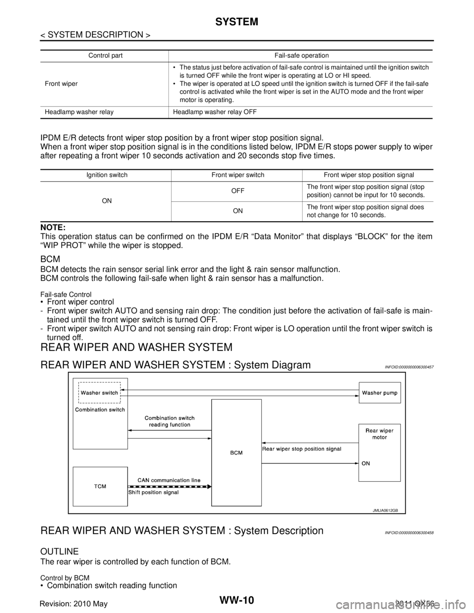
REAR WIPER AND WASHER SYSTEM : System DiagramINFOID:0000000006300457
REAR WIPER AND WASHER S YSTEM : System DescriptionINFOID:0000000006300458
OUTLINE
The rear wiper is controlled by each function of BCM.
Control by BCM
Combination switch reading function
Control part Fail-safe operation
Front wiper The status just before activation of fail-safe control is maintained until the ignition switch
is turned OFF while the front wiper is operating at LO or HI speed.
The wiper is operated at LO speed until the ignition switch is turned OFF if the fail-safe
control is activated while the front wiper is set in the AUTO mode and the front wiper
motor is operating.
Headlamp washer relay Headlamp washer relay OFF
Ignition switch Front wiper switch Front wiper stop position signal
ON OFF
The front wiper stop position signal (stop
position) cannot be input for 10 seconds.
ON The front wiper stop position signal does
not change for 10 seconds.
JMLIA0612GB
Revision: 2010 May2011 QX56