2011 INFINITI QX56 brake fluid
[x] Cancel search: brake fluidPage 3777 of 5598

MWI-34
< SYSTEM DESCRIPTION >
DIAGNOSIS SYSTEM (COMBINATION METER)
Display item Description
ABS W/L Lighting history of ABS warning lamp.
VDC/TCS IND Lighting history of VDC OFF indicator lamp.
SLIP IND Lighting history of VDC warning lamp.
BRAKE W/L Lighting history of brake warning lamp.
DOOR W/L Lighting history of door open warning.
TRUNK/GLAS-H This item is displa yed, but cannot be monitored.
OIL W/L Lighting history of oil pressure warning lamp.
C-ENG W/L Lighting history of malfunction indicator lamp.
C-ENG2 W/L This item is displayed, but cannot be monitored.
CRUISE IND Lighting history of CRUISE indicator lamp.
SET IND Lighting history of SET indicator lamp.
CRUISE W/L Lighting history of CRUISE warning lamp.
BA W/L Lighting history of IBA OFF indicator lamp.
O/D OFF IND This item is displayed, but cannot be monitored.
ATC/T-AMT W/L Lighting history of A/T CHECK warning lamp.
ATF TEMP W/L This item is displayed, but cannot be monitored.
CVT IND This item is displayed, but cannot be monitored.
SPORT IND This item is displayed, but cannot be monitored.
4WD W/L Lighting history of 4WD warning lamp.
FUEL W/L Lighting history of low fuel level warning.
WASHER W/L Lighting history of low washer fluid warning.
AIR PRES W/L Lighting history of low tire pressure warning lamp.
KEY G/Y W/L Lighting history of KEY warning lamp.
KEY R W/L This item is displaye d, but cannot be monitored.
KEY KNOB W/L This item is displa yed, but cannot be monitored.
EPS W/L This item is displayed, but cannot be monitored.
e-4WD This item is displayed, but cannot be monitored.
AFS OFF IND This item is displayed, but cannot be monitored.
4WAS/RAS W/L This item is displayed, but cannot be monitored.
HDC W/L This item is displayed, but cannot be monitored.
SYS FAIL W/L This item is displa yed, but cannot be monitored.
SFT POSI W/L This item is displayed, but cannot be monitored.
HV BAT W/L This item is displayed, but cannot be monitored.
HEV BRAKE W/L This item is displayed, but cannot be monitored.
SFT OPER W/L This item is displayed, but cannot be monitored.
LANE W/L Lighting history of lane departure warning lamp.
CHAGE W/L This item is displayed, but cannot be monitored.
OIL LEV LOW This item is displayed, but cannot be monitored.
DPF W/L This item is displayed, but cannot be monitored.
TRAILER IND This item is displayed, but cannot be monitored.
RUN FLAT W/L This item is displa yed, but cannot be monitored.
E-SUS W/L This item is displayed, but cannot be monitored.
LAUNCH CNT W/L This item is displayed, but cannot be monitored.
BRAKE PAD W/L This item is displa yed, but cannot be monitored.
Revision: 2010 May2011 QX56
Page 3781 of 5598

MWI-38
< ECU DIAGNOSIS INFORMATION >
COMBINATION METER
SHIFT INDIgnition switch
ONDuring the indication of “P” by shift position
indicator
P
During the indication of “R” by shift position
indicator R
During the indication of “N” by shift position
indicator N
During the indication of “D” by shift position
indicator D
During the indication of “M1” by shift posi-
tion indicator M1
During the indication of “M2” by shift posi-
tion indicator M2
During the indication of “M3” by shift posi-
tion indicator M3
During the indication of “M4” by shift posi-
tion indicator M4
During the indication of “M5” by shift posi-
tion indicator M5
During the indication of “M6” by shift posi-
tion indicator M6
During the indication of “M7” by shift posi-
tion indicator M7
4WD IND Ignition switch
ON4WD shift switch in AUTO position AUTO
4WD shift switch in 4H position LOCK
4WD shift switch in 4L position LOCK/4Lo
BSW IND Ignition switch
ONNOTE:
This item is displayed, but cannot be moni-
tored.
Off
BSW W/L Ignition switch
ONBSW warning lamp ON On
BSW warning lamp OFF Off
AT S MODE SW Ignition switch
ONSnow mode switch ON On
Snow mode switch OFF Off
M RANGE SW Ignition switch
ONSelector lever in manual mode position On
Other than the above Off
NM RANGE SW Ignition switch
ONSelector lever in manual mode position Off
Other than the above On
AT SFT UP SW Ignition switch
ONSelector lever in + position On
Other than the above Off
AT SFT DWN SW Ignition switch
ONSelector lever in – position On
Other than the above Off
PKB SW Ignition switch
ONParking brake switch ON On
Parking brake switch OFF Off
BUCKLE SW Ignition switch
ONDriver seat belt not fastened On
Driver seat belt fastened Off
BRAKE OIL SW Ignition switch
ONBrake fluid level switch ON On
Brake fluid level switch OFF Off
A/C AMP CONN Ignition switch
ONNOTE:
This item is displayed, but cannot be moni-
tored.
Off
Monitor Item Condition Value/Status
Revision: 2010 May2011 QX56
Page 4273 of 5598

RSU-18
< UNIT REMOVAL AND INSTALLATION >
REAR SUSPENSION MEMBER
UNIT REMOVAL AND INSTALLATION
REAR SUSPENSION MEMBER
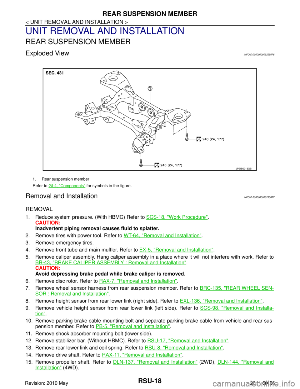
Exploded ViewINFOID:0000000006225676
Removal and InstallationINFOID:0000000006225677
REMOVAL
1. Reduce system pressure. (With HBMC) Refer to SCS-18, "Work Procedure".
CAUTION:
Inadvertent piping removal causes fluid to splatter.
2. Remove tires with power tool. Refer to WT-64, "
Removal and Installation".
3. Remove emergency tires.
4. Remove front tube and main muffler. Refer to EX-5, "
Removal and Installation".
5. Remove caliper assembly. Hang caliper assembly in a place where it will not interfere with work. Refer to BR-43, "
BRAKE CALIPER ASSEMBLY : Removal and Installation".
CAUTION:
Avoid depressing brake pedal wh ile brake caliper is removed.
6. Remove disc rotor. Refer to RAX-7, "
Removal and Installation".
7. Remove wheel sensor harness from rear suspension member. Refer to BRC-135, "
REAR WHEEL SEN-
SOR : Removal and Installation".
8. Remove height sensor from rear lower link (right side). Refer to EXL-136, "
Removal and Installation".
9. Remove vehicle height sensor from rear lower link (left side). Refer to SCS-98, "
Removal and Installa-
tion".
10. Remove parking brake cable mounting bolt and separa te parking brake cable from vehicle and rear sus-
pension member. Refer to PB-5, "
Removal and Installation".
11. Remove shock absorber mounting bolt (lower side).
12. Remove stabilizer bar. (Without HBMC). Refer to RSU-17, "
Removal and Installation".
13. Remove rear lower link and coil spring. Refer to RSU-8, "
Removal and Installation".
14. Remove drive shaft. Refer to RAX-11, "
Removal and Installation".
15. Remove propeller shaft. Refer to DLN-137, "
Removal and Installation" (2WD), DLN-144, "Removal and
Installation" (4WD).
1. Rear suspension member
Refer to GI-4, "
Components" for symbols in the figure.
JPEIB0218GB
Revision: 2010 May2011 QX56
Page 4365 of 5598
![INFINITI QX56 2011 Factory Service Manual
PRECAUTIONSSCS-5
< PRECAUTION > [HBMC]
C
D
F
G H
I
J
K L
M A
B
SCS
N
O P
5. When the repair work is completed, re-connect both battery cables. With the brake pedal released, turn
the push-button ign INFINITI QX56 2011 Factory Service Manual
PRECAUTIONSSCS-5
< PRECAUTION > [HBMC]
C
D
F
G H
I
J
K L
M A
B
SCS
N
O P
5. When the repair work is completed, re-connect both battery cables. With the brake pedal released, turn
the push-button ign](/manual-img/42/57033/w960_57033-4364.png)
PRECAUTIONSSCS-5
< PRECAUTION > [HBMC]
C
D
F
G H
I
J
K L
M A
B
SCS
N
O P
5. When the repair work is completed, re-connect both battery cables. With the brake pedal released, turn
the push-button ignition switch from ACC position to ON position, then to LOCK position. (The steering
wheel will lock when the push-button ignition switch is turned to LOCK position.)
6. Perform self-diagnosis check of a ll control units using CONSULT-III.
Precaution for Procedure without Cowl Top CoverINFOID:0000000006256138
When performing the procedure after removing cowl top cover, cover
the lower end of windshield with urethane, etc.
Precaution for Hydraulic Body-Motion Control SystemINFOID:0000000006255996
WARNING:
Always check the piping for loose co nnections, damage, or twists before starting operation, since
pressure in hydraulic circuit becom es high during air bleeding operation.
When repairing or replacing a malfunctioning pa rt, always release pressure from hydraulic circuit,
since dangerous conditions may be created when oil leakage occurs during air bleeding operation.
Clean surrounding areas of oil inlet and air bleeder usi ng steam before starting operation, since there may
be mud on it.
Always decrease pressure when removing a system related part, since system pressure is high.
Seal the removed part using vinyl tape for preventi ng dirt from getting on or entering the removed part.
Check system pressure again 1 day or more after bleeding operation is complete, since system pressure may decrease when air bleeding is insufficient.
Use Genuine NISSAN Hydraulic Suspension Fluid for suspension fluid.
Never reuse drained suspension fluid.
Check for suspension fluid leakage after removing a system-related part.
PIIB3706J
Revision: 2010 May2011 QX56
Page 4406 of 5598
![INFINITI QX56 2011 Factory Service Manual
SCS-46
< REMOVAL AND INSTALLATION >[HBMC]
HYDRAULIC BODY-MOTION CONTROL SYSTEM
3. Remove lower side pipe (A) of rear shock absorber RH.
4. Remove pipe (A) from left side rear joint (B).
5. Remove mou INFINITI QX56 2011 Factory Service Manual
SCS-46
< REMOVAL AND INSTALLATION >[HBMC]
HYDRAULIC BODY-MOTION CONTROL SYSTEM
3. Remove lower side pipe (A) of rear shock absorber RH.
4. Remove pipe (A) from left side rear joint (B).
5. Remove mou](/manual-img/42/57033/w960_57033-4405.png)
SCS-46
< REMOVAL AND INSTALLATION >[HBMC]
HYDRAULIC BODY-MOTION CONTROL SYSTEM
3. Remove lower side pipe (A) of rear shock absorber RH.
4. Remove pipe (A) from left side rear joint (B).
5. Remove mounting bolts of bracket of rear tube assembly B.
6. Remove mounting bolts of bracket of rear left brake hose, and
then free hose.
7. Remove rear tube assembly B from the vehicle.
8. Perform inspection after removal. Refer to SCS-46, "
REAR
TUBE ASSEMBLY : Inspection".
INSTALLATION
Note the following, and install in the reverse order of removal.
Apply genuine NISSAN hydraulic suspension fluid to O-ring.
Check connection portion of each piping for dirt or dust.
REAR TUBE ASSEMBLY : InspectionINFOID:0000000006256034
INSPECTION AFTER REMOVAL
O-ring must be free of scratches and damage.
Pipe and tube must be free of scratches and damage.
INSPECTION AFTER INSTALLATION
Check oil leakage, twists, deformation, contact with other parts, and loose connections.
ADJUSTMENT AFTER INSTALLATION
Perform air bleeding. Refer to SCS-18, "Work Procedure".
JSEIA0212ZZ
JSEIA0204ZZ
Revision: 2010 May2011 QX56
Page 5001 of 5598

ST-14
< BASIC INSPECTION >
STEERING WHEEL
STEERING WHEEL
InspectionINFOID:0000000006225584
NEUTRAL POSITION STEERING WHEEL
1. Check that steering gear assembly, steering column assembly and steering wheel are installed in the cor-
rect position.
2. Perform neutral position inspection after wheel alignment. Refer to FSU-7, "
Inspection".
3. Set vehicle to the straight-ahead position and c onfirm steering wheel is in the neutral position.
4. Loosen outer socket lock nut and turn inner socket to left and right equally to make fine adjustments if steering wheel is not in the neutral position.
STEERING WHEEL TURNING FORCE
1. Park vehicle on a level and dry surface, set parking brake.
2. Tires need to be inflated the specified pressure. Refer to WT-69, "
Tire Air Pressure".
3. Start the engine.
4. Bring power steering fluid up to adequate operating temperature.
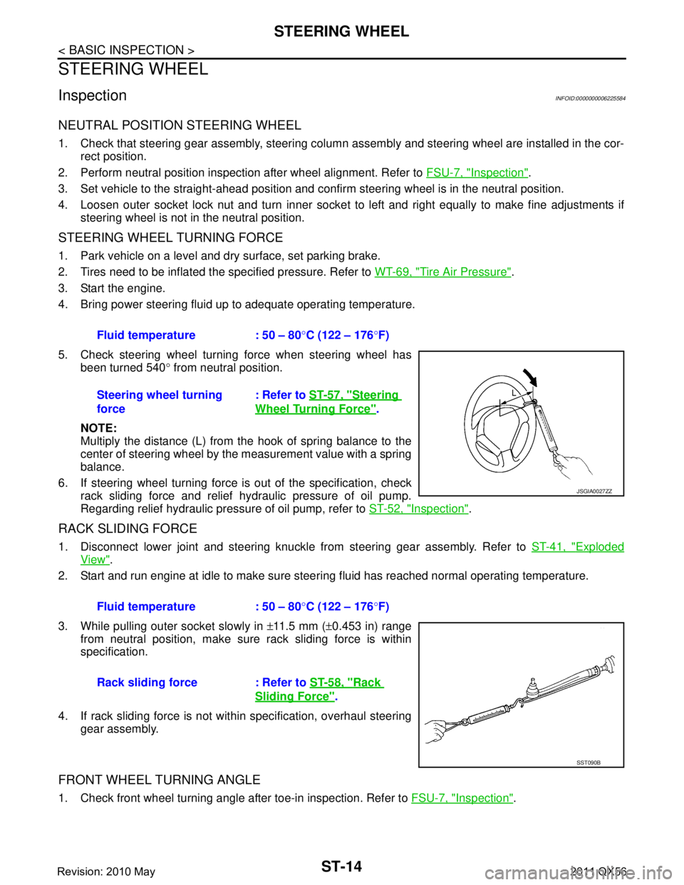
5. Check steering wheel turning force when steering wheel has been turned 540 ° from neutral position.
NOTE:
Multiply the distance (L) from the hook of spring balance to the
center of steering wheel by the measurement value with a spring
balance.
6. If steering wheel turning force is out of the specification, check
rack sliding force and relief hydraulic pressure of oil pump.
Regarding relief hydraulic pressure of oil pump, refer to ST-52, "
Inspection".
RACK SLIDING FORCE
1. Disconnect lower joint and steering knuckle from steering gear assembly. Refer to ST-41, "Exploded
View".
2. Start and run engine at idle to make sure steer ing fluid has reached normal operating temperature.
3. While pulling outer socket slowly in ±11.5 mm ( ±0.453 in) range
from neutral position, make sure rack sliding force is within
specification.
4. If rack sliding force is not within specification, overhaul steering gear assembly.
FRONT WHEEL TURNING ANGLE
1. Check front wheel turning angle after toe-in inspection. Refer to FSU-7, "Inspection".
Fluid temperature : 50 – 80
°C (122 – 176 °F)
Steering wheel turning
force : Refer to
ST-57, "
Steering
Wheel Turning Force".
JSGIA0027ZZ
Fluid temperature : 50 – 80 °C (122 – 176 °F)
Rack sliding force : Refer to ST-58, "
Rack
Sliding Force".
SST090B
Revision: 2010 May2011 QX56
Page 5016 of 5598

NOISE, VIBRATION AND HARSHNESS (NVH) TROUBLESHOOTINGST-29
< SYMPTOM DIAGNOSIS >
C
DE
F
H I
J
K L
M A
B
ST
N
O P
NOISE, VIBRATION AND HARSHN ESS (NVH) TROUBLESHOOTING
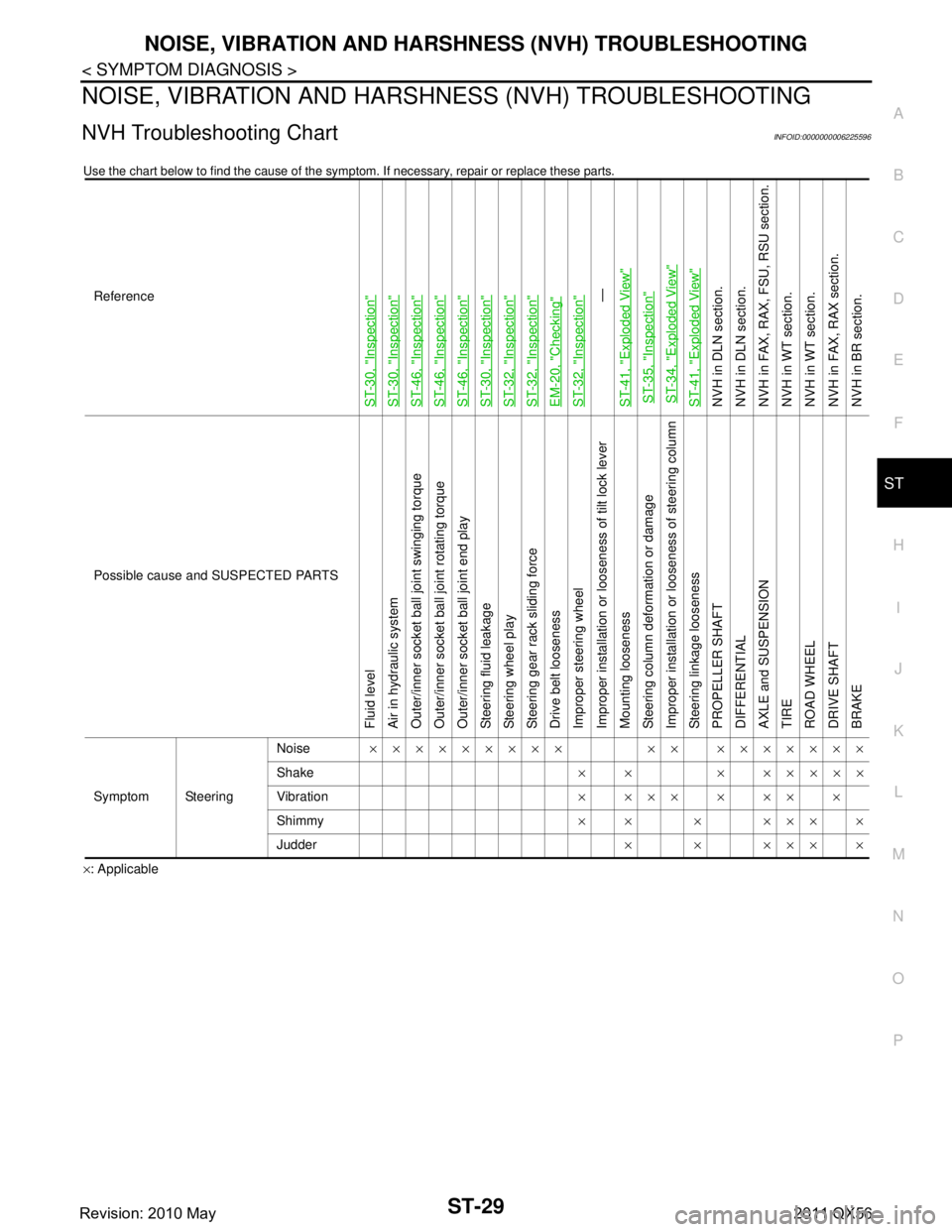
NVH Troubleshooting ChartINFOID:0000000006225596
Use the chart below to find the cause of the symp tom. If necessary, repair or replace these parts.
×: ApplicableReference
ST-30, "
Inspection
"
ST-30, "
Inspection
"
ST-46, "
Inspection
"
ST-46, "
Inspection
"
ST-46, "
Inspection
"
ST-30, "
Inspection
"
ST-32, "
Inspection
"
ST-32, "
Inspection
"
EM-20, "
Checking
"
ST-32, "
Inspection
"—
ST-41, "
Exploded View
"
ST-35, "
Inspection
"
ST-34, "
Exploded View
"
ST-41, "
Exploded View
"
NVH in DLN section.
NVH in DLN section.
NVH in FAX, RAX, FSU, RSU section.
NVH in WT section.
NVH in WT section.
NVH in FAX, RAX section.
NVH in BR section.
Possible cause and SUSPECTED PARTS
Fluid level
Air in hydraulic system
Outer/inner socket ball joint swinging torque
Outer/inner socket ball joint rotating torque
Outer/inner socket ball joint end play
Steering fluid leakage
Steering wheel play
Steering gear rack sliding force
Drive belt looseness
Improper steering wheel
Improper installation or looseness of tilt lock lever
Mounting looseness
Steering column deformation or damage
Improper installation or looseness of steering column
Steering linkage looseness
PROPELLER SHAFT
DIFFERENTIAL
AXLE and SUSPENSION
TIRE
ROAD WHEEL
DRIVE SHAFT
BRAKE
Symptom Steering Noise
××××××××× ×× ×××××××
Shake × × × ×××××
Vibration ××××××××
Shimmy ×× × ××××
Judder ××××××
Revision: 2010 May2011 QX56
Page 5089 of 5598

TM-1
TRANSMISSION & DRIVELINE
CEF
G H
I
J
K L
M
SECTION TM
A
B
TM
N
O P
CONTENTS
TRANSAXLE & TRANSMISSION
7AT: RE7R01B
PRECAUTION ................ ...............................
6
PRECAUTIONS .............................................. .....6
Precaution for Supplemental Restraint System
(SRS) "AIR BAG" and "SEAT BELT PRE-TEN-
SIONER" ............................................................. ......
6
General Precautions .................................................6
Service Notice or Precaution .....................................7
PREPARATION ............................................8
PREPARATION .............................................. .....8
Special Service Tool ........................................... ......8
Commercial Service Tool ..........................................9
SYSTEM DESCRIPTION .............................10
COMPONENT PARTS ................................... ....10
A/T CONTROL SYSTEM ...........................................10
A/T CONTROL SYSTEM : Component Parts Lo-
cation ................................................................... ....
10
A/T CONTROL SYSTEM : Component Descrip-
tion ...................................................................... ....
11
A/T CONTROL SYSTEM : TCM .............................12
A/T CONTROL SYSTEM : Transmission Range
Switch .................................................................. ....
12
A/T CONTROL SYSTEM : Input Speed Sensor .....12
A/T CONTROL SYSTEM : Output Speed Sensor ....12
A/T CONTROL SYSTEM : A/ T Fluid Temperature
Sensor ................................................................. ....
12
A/T CONTROL SYSTEM : Input Clutch Solenoid
Valve ................................................................... ....
12
A/T CONTROL SYSTEM : Front Brake Solenoid
Valve ................................................................... ....
12
A/T CONTROL SYSTEM : Direct Clutch Solenoid
Valve ................................................................... ....
12
A/T CONTROL SYSTEM : High and Low Reverse
Clutch Solenoid Valve ......................................... ....
13
A/T CONTROL SYSTEM : Low Brake Solenoid
Valve .................................................................... ....
13
A/T CONTROL SYSTEM : Anti-interlock Solenoid
Valve ........................................................................
13
A/T CONTROL SYSTEM : 2346 Brake Solenoid
Valve ........................................................................
13
A/T CONTROL SYSTEM : Torque Converter
Clutch Solenoid Valve ......................................... ....
13
A/T CONTROL SYSTEM : Line Pressure Solenoid
Valve .................................................................... ....
13
A/T CONTROL SYSTEM : Accelerator Pedal Po-
sition Sensor ........................................................ ....
13
A/T CONTROL SYSTEM : Manual Mode Switch ....13
A/T CONTROL SYSTEM : To w Mode Switch .........14
A/T CONTROL SYSTEM : A/T CHECK Indicator
Lamp .................................................................... ....
14
A/T CONTROL SYSTEM : Tow Mode Indicator
Lamp .................................................................... ....
14
A/T CONTROL SYSTEM : Selector Lever Position
Indicator ............................................................... ....
14
A/T SHIFT LOCK SYSTEM ................................... ....14
A/T SHIFT LOCK SYSTEM : Component Parts
Location ...................................................................
15
A/T SHIFT LOCK SYSTEM : Component Descrip-
tion ...........................................................................
15
STRUCTURE AND OPERATION .....................16
TRANSMISSION .................................................... ....16
TRANSMISSION : Cross-Sectional View ................16
TRANSMISSION : System Diagram ........................18
TRANSMISSION : System Description ...................18
TRANSMISSION : Component Description .............41
FLUID COOLER & FLUID WARMER SYSTEM .... ....41
FLUID COOLER & FLUID WARMER SYSTEM :
System Description ..................................................
41
SYSTEM ............................................................44
A/T CONTROL SYSTEM ....................................... ....44
Revision: 2010 May2011 QX56