2011 INFINITI QX56 brake fluid
[x] Cancel search: brake fluidPage 3697 of 5598
CHASSIS MAINTENANCEMA-27
< PERIODIC MAINTENANCE >
C
DE
F
G H
I
J
K L
M B
MA
N
O A
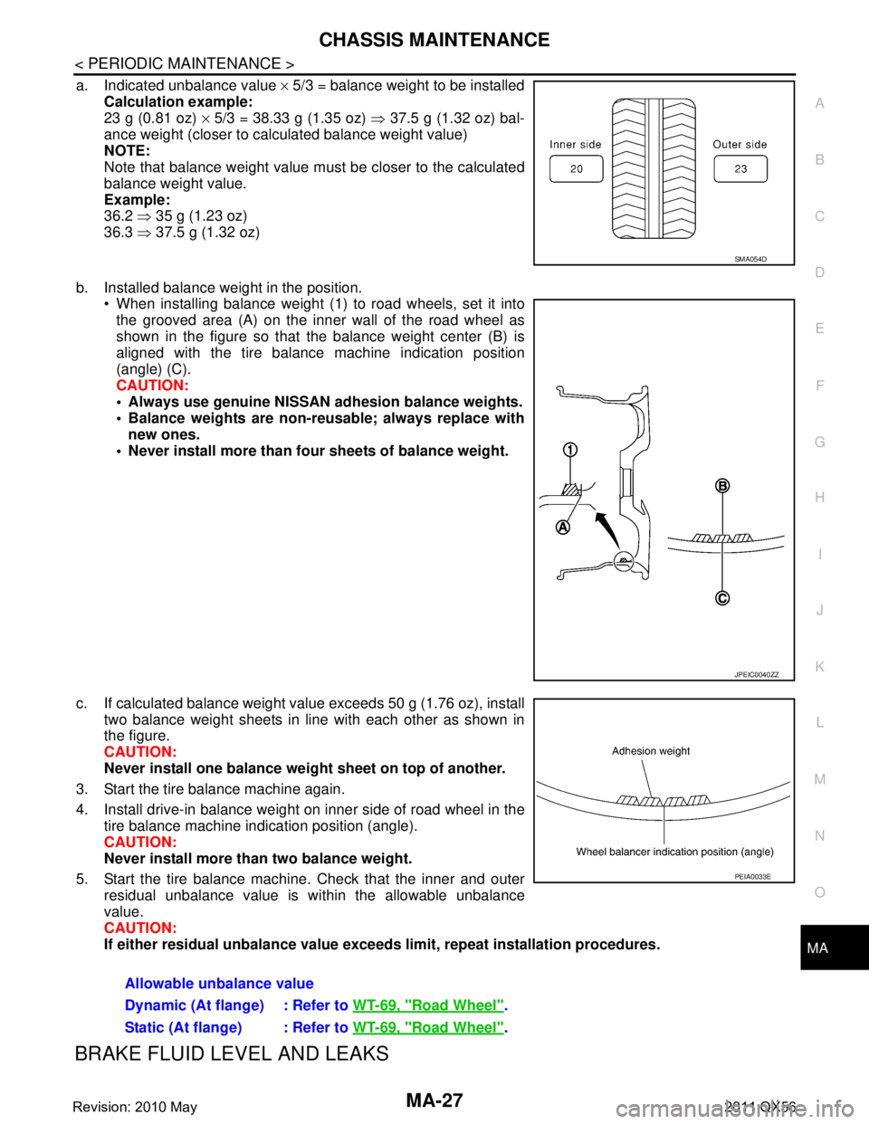
a. Indicated unbalance value
× 5/3 = balance weight to be installed
Calculation example:
23 g (0.81 oz) × 5/3 = 38.33 g (1.35 oz) ⇒ 37.5 g (1.32 oz) bal-
ance weight (closer to calculated balance weight value)
NOTE:
Note that balance weight value must be closer to the calculated
balance weight value.
Example:
36.2 ⇒ 35 g (1.23 oz)
36.3 ⇒ 37.5 g (1.32 oz)
b. Installed balance weight in the position. When installing balance weight (1) to road wheels, set it into
the grooved area (A) on the inner wall of the road wheel as
shown in the figure so that the balance weight center (B) is
aligned with the tire balance machine indication position
(angle) (C).
CAUTION:
Always use genuine NISSAN ad hesion balance weights.
Balance weights are non-re usable; always replace with
new ones.
Never install more than four sheets of balance weight.
c. If calculated balance weight value exceeds 50 g (1.76 oz), install two balance weight sheets in line with each other as shown in
the figure.
CAUTION:
Never install one balance weight sheet on top of another.
3. Start the tire balance machine again.
4. Install drive-in balance weight on inner side of road wheel in the tire balance machine indication position (angle).
CAUTION:
Never install more than two balance weight.
5. Start the tire balance machine. Check that the inner and outer residual unbalance value is within the allowable unbalance
value.
CAUTION:
If either residual unbalan ce value exceeds limit, repeat installation procedures.
BRAKE FLUID LEVEL AND LEAKS
SMA054D
JPEIC0040ZZ
Allowable unbalance value
Dynamic (At flange) : Refer to WT-69, "
Road Wheel".
Static (At flange) : Refer to WT-69, "
Road Wheel".
PEIA0033E
Revision: 2010 May2011 QX56
Page 3698 of 5598
MA-28
< PERIODIC MAINTENANCE >
CHASSIS MAINTENANCE
BRAKE FLUID LEVEL AND LEAKS : Inspection
INFOID:0000000006220939
Check that the fluid level in the sub tank is within the specified range (MAX – MIN lines).
CAUTION:
Turn OFF the ignition switch an d depress the brake pedal 20 times or more to check brake fluid level.
NOTE:
Since brake fluid is in the accumulator in pressurized condition, the reservoir tank brake fluid level should be
lower than the MAX line.
Visually check for any brake fluid leakage around the reservoir tank.
Check the brake system for any leakage if the fl uid level is extremely low (lower than MIN).
Check the brake system for fluid leakage if the warn ing lamp remains illuminated even after the parking
brake is released.
Check the sub tank for the mixing of foreign ma tter (e.g. dust) and oils other than brake fluid.
BRAKE LINES AND CABLES
BRAKE LINES AND CABLES : InspectionINFOID:0000000006220940
1. Check brake line (tubes and hoses) for cracks, deterioration or other damage. Replace any damaged
parts.
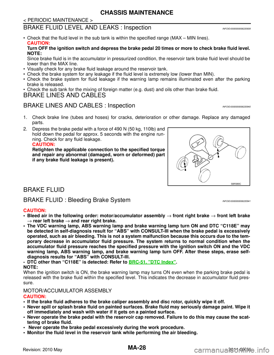
2. Depress the brake pedal with a force of 490 N (50 kg, 110lb) and hold down the pedal for approx. 5 seconds with the engine run-
ning. Check for any fluid leakage.
CAUTION:
Retighten the applicable conn ection to the specified torque
and repair any abnormal (damag ed, worn or deformed) part
if any brake fluid leakage is present).
BRAKE FLUID
BRAKE FLUID : Bleeding Brake SystemINFOID:0000000006220941
CAUTION:
Bleed air in the following order: motor/accumulator assembly → front right brake → front left brake
→ rear left brake → and rear right brake.
The VDC warning lamp, ABS warning lamp and br ake warning lamp turn ON and DTC “C118E” may
be detected in self-diagnosis r esult for “ABS” with CONSULT-II I when the brake pedal is excessively
operated, such as air bleeding. Thi s is not a system malfunction becau se this occurs due to the tem-
porary decrease in accumulator fl uid pressure. The system returns to normal condition when the
accumulator fluid pressure reaches the specified pressu re with the ignition switch ON and the VDC
warning lamp, ABS warning lamp, and brake warnin g lamp turn OFF. After these steps, erase self-
diagnosis results for “ABS” with CONSULT-III.
- DTC other than “C118E” is detected: Refer to BRC-51, "
DTC Index".
NOTE:
When the ignition switch is ON, the brake warning la mp may turns ON even when the parking brake pedal is
released with the brake fluid within the specified level. This indicates the decrease in accumulator fluid pres-
sure.
MOTOR/ACCUMULATOR ASSEMBLY
CAUTION:
If the brake fluid adheres to the brake caliper assembly and disc rotor, quickly wipe it off.
Never spill or splash brake fluid on painted surfaces. Brake fluid may seriously damage paint. Wipe it
off immediately and wash with wate r if it gets on a painted surface.
Never operate the brake pedal with the reservoir cap removed. Failure to do this may cause the scat-
tering of brake fluid.
Never operate the brake pedal excessively during the work procedure.
Monitor the fluid level in the reservoir tank while performing the air bleeding.
SBR389C
Revision: 2010 May2011 QX56
Page 3699 of 5598
CHASSIS MAINTENANCEMA-29
< PERIODIC MAINTENANCE >
C
DE
F
G H
I
J
K L
M B
MA
N
O A
Bleed air in the following
order: motor/accumulator assembly → front right brake → front left brake
→ rear left brake → and rear right brake.
1. Turn the ignition switch OFF.
2. Depress the brake pedal 20 times or more.
3. Check that there is no foreign material in t he reservoir tank, and refill with new brake fluid.
CAUTION:
Never reuse drained brake fluid.
Never allow oils other than brake fl uid to enter the reservoir tank.
4. Turn the ignition switch ON. NOTE:
The motor is activated and automatically stops.
5. Turn the ignition switch OFF.
6. Depress the brake pedal 20 times or more. NOTE:
The pressure loss in the accumulator results in a large brake pedal stroke. In addition to this, the brake
pedal depression becomes lighter in initial stage.
7. Repeat steps 4 to 6 for 5 times.
8. Turn the ignition switch ON to check that the time between motor activation and automatic stop is less
than 18 seconds. If the time is 18 seconds or more, repeat from Step 4 to 8.
FRONT BRAKE
CAUTION:
If the brake fluid adheres to the brake caliper assembly and disc rotor, quickly wipe it off.
Never spill or splash brake fluid on painted surfaces. Brake fluid may seriously damage paint. Wipe it
off immediately and wash with wate r if it gets on a painted surface.
Never operate the brake pedal with the reservoir cap removed. Failure to do this may cause the scat-
tering of brake fluid.
Never operate the brake pedal excessively during the work procedure.
Monitor the fluid level in the reservoir tank while performing the air bleeding.
Bleed air in the following order: motor/accumulator assembly → front right brake → front left brake
→ rear left brake → and rear right brake.
1. Turn the ignition switch OFF.
2. Depress the brake pedal 20 times or more. NOTE:
The pressure loss in the accumulator results in a large brake pedal stroke. In addition to this, the brake
pedal depression becomes lighter in initial stage.
3. Check that there is no foreign material in t he reservoir tank, and refill with new brake fluid.
CAUTION:
Never reuse drained brake fluid.
Never allow oils other than brake fl uid to enter the reservoir tank.
4. Turn the ignition switch ON.
5. Connect a vinyl tube to the bleed valve.
6. Depress the brake pedal and loosen the bleeder valve.
7. Repeat steps 1 to 6 until all of the air is out of the brake line and tighten the air bleeder to the specified
torque with the brake pedal depressed. Refer to BR-36, "
BRAKE CALIPER ASSEMBLY : Exploded View".
8. Check that no drag feel is present for the front disc brake. Refer to BR-39, "
BRAKE CALIPER ASSEMBLY
: Inspection".
9. Check each item of brake pedal. Adjust it if t he measurement value is not the standard. Refer to BR-7,
"Inspection and Adjustment".
REAR BRAKE
CAUTION:
If the brake fluid adheres to the brake caliper assembly and disc rotor, quickly wipe it off.
Never spill or splash brake fluid on painted surfaces. Brake fluid may seriously damage paint. Wipe it
off immediately and wash with wate r if it gets on a painted surface.
Never operate the brake pedal with the reservoir cap removed. Failure to do this may cause the scat-
tering of brake fluid.
Revision: 2010 May2011 QX56
Page 3700 of 5598
MA-30
< PERIODIC MAINTENANCE >
CHASSIS MAINTENANCE
Never operate the brake pedal excessively during the work procedure.
Monitor the fluid level in the reservoir tank while performing the air bleeding.
Bleed air in the following order: motor/accumulator assembly → front right brake → front left brake
→ rear left brake → and rear right brake.
1. Turn the ignition switch OFF.
2. Depress the brake pedal 20 times or more. NOTE:
The pressure loss in the accumulator results in a large brake pedal stroke. In addition to this, the brake
pedal depression becomes lighter in initial stage.
3. Check that there is no foreign material in the reservoir tank, and refill with new brake fluid. CAUTION:
Never reuse drained brake fluid.
Never allow oils other than brake fluid to enter the reservoir tank.
4. Turn the ignition switch ON.
5. Connect a vinyl tube to the bleed valve.
6. Depress the brake pedal and loosen the bleeder valve.
7. Depress and hold the brake pedal depression to dischar ge 100 cc of brake fluid before tightening the air
bleeder to the specified torque. Refer to BR-42, "
BRAKE CALIPER ASSEMBLY : Exploded View".
NOTE:
Since brake fluid is conveyed by the motor, the brake pedal is not necessarily depressed.
8. Release the brake pedal.
9. Repeat steps 1 to 8 until all of the air is out of the brake line and tighten the air bleeder to the specified
torque with the brake pedal depressed. Refer to BR-42, "
BRAKE CALIPER ASSEMBLY : Exploded View".
10. Check that no drag feel is present for the rear disc brake. Refer to BR-45, "
BRAKE CALIPER ASSEMBLY
: Inspection".
11. Check each item of brake pedal. Adjust it if t he measurement value is not the standard. Refer to BR-7,
"Inspection and Adjustment".
BRAKE FLUID LEVEL ADJUSTMENT AFTER AIR BLEEDING
1. Turn the ignition switch OFF.
2. Depress the brake pedal 20 times or more.
NOTE:
The pressure loss in the accumulator results in a large brake pedal stroke. In addition to this, the brake
pedal depression becomes lighter in initial stage.
3. Adjust brake fluid level to the reservoir tank MAX line. CAUTION:
Never adjust with the ignition switch ON.
4. Turn the ignition switch ON.
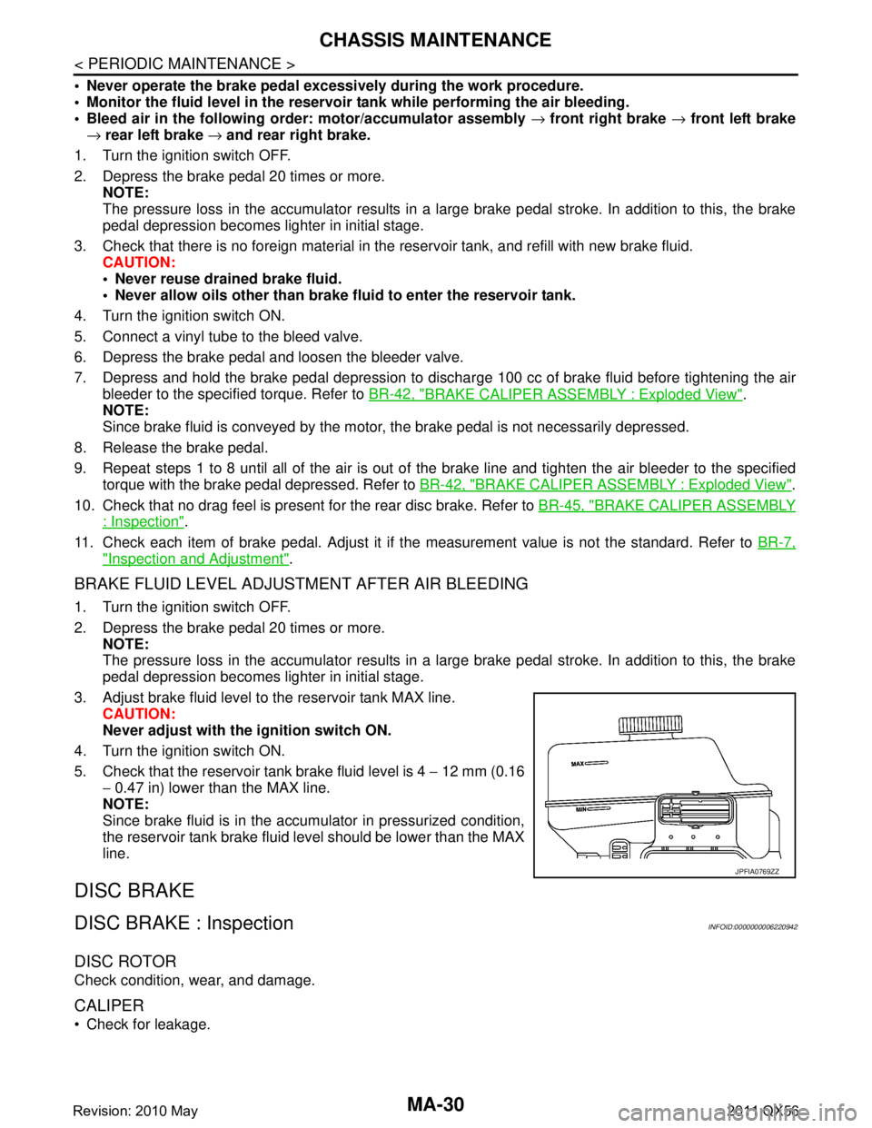
5. Check that the reservoir tank brake fluid level is 4 − 12 mm (0.16
− 0.47 in) lower than the MAX line.
NOTE:
Since brake fluid is in the accumulator in pressurized condition,
the reservoir tank brake fluid level should be lower than the MAX
line.
DISC BRAKE
DISC BRAKE : InspectionINFOID:0000000006220942
DISC ROTOR
Check condition, wear, and damage.
CALIPER
Check for leakage.
JPFIA0769ZZ
Revision: 2010 May2011 QX56
Page 3754 of 5598
MWI
SYSTEMMWI-11
< SYSTEM DESCRIPTION >
C
DE
F
G H
I
J
K L
M B A
O P
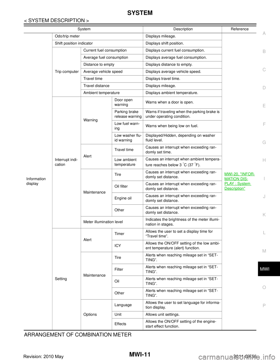
ARRANGEMENT OF COMBINATION METER
Information
display Odo/trip meter Displays mileage.
MWI-20, "
INFOR-
MATION DIS-
PLAY : System
Description"
Shift position indicator Displays shift position.
Trip computerCurrent fuel consumption Displays current fuel consumption.
Average fuel consumption Displays average fuel consumption.
Distance to empty Displays distance to empty.
Average vehicle speed Displays average vehicle speed.
Travel time Displays travel time.
Travel distance Displays mileage.
Ambient temperature Displays ambient temperature.
Interrupt indi-
cation Warning
Door open
warning
Warns when a door is open.
Parking brake
release warning Warns if traveling when the parking brake is
under operating condition.
Low fuel warn-
ing Warns when being low on fuel.
Low washer flu-
id warning Displayed/Hidden, depending on washer
fluid level.
Alert Travel time
Causes an interrupt when exceeding ran-
domly set time.
Low ambient
temperature Causes an interrupt when ambient tempera-
ture reaches below 3
°C (37 °F).
Maintenance Tire
Causes an interrupt when exceeding ran-
domly set distance.
Oil filter Causes an interrupt when exceeding ran-
domly set distance.
Engine oil Causes an interrupt when exceeding ran-
domly set distance.
Other Causes an interrupt when exceeding ran-
domly set distance.
Meter illumination level Indicates the brightness of the meter illumi-
nation in stages.
Setting Alert
Timer
Allows the user to set a display time for
“Travel time”.
ICY Allows the ON/OFF setting of the low ambi-
ent temperature (alert) function.
Maintenance Tire
Alerts when reaching mileage set in “SET-
TING”.
Filter Alerts when reaching mileage set in “SET-
TING”.
Oil Alerts when reaching mileage set in “SET-
TING”.
Other Alerts when reaching mileage set in “SET-
TING”.
Options Language
Allows the user to set language for informa-
tion display.
Unit Allows unit settings.
Effects Allows the ON/OFF setting of the engine-
start effect function.
System Description Reference
Revision: 2010 May2011 QX56
Page 3759 of 5598
MWI-16
< SYSTEM DESCRIPTION >
SYSTEM
OIL PRESSURE WARNING LAMP : System Description
INFOID:0000000006221709
IPDM E/R reads the ON/OFF signals fr om the oil pressure switch and transmits the oil pressure switch sig-
nal to the combination meter via BCM with the CAN communication.
The combination meter turns the oil pressure warning lamp ON (at the time of a reduction in hydraulic pres-
sure)/OFF (except at the time of a reduction in hydraulic pressure) according to the oil pressure switch signal
received via CAN communication.
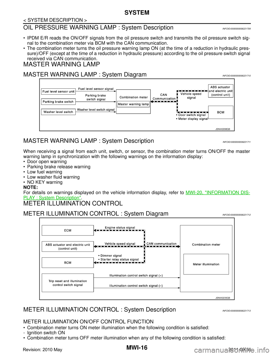
MASTER WARNING LAMP
MASTER WARNING LAMP : System DiagramINFOID:0000000006221710
MASTER WARNING LAMP : System DescriptionINFOID:0000000006221711
When receiving a signal from each unit, switch, or s ensor, the combination meter turns ON/OFF the master
warning lamp in synchronization with the following warnings on the information display:
Door open warning
Parking brake release warning
Low fuel warning
Low washer fluid warning
NO KEY warning
NOTE:
For details on warnings displayed on the vehicle information display, refer to MWI-20, "
INFORMATION DIS-
PLAY : System Description".
METER ILLUMINATION CONTROL
METER ILLUMINATION CONTROL : System DiagramINFOID:0000000006221712
METER ILLUMINATION CONTRO L : System DescriptionINFOID:0000000006221713
METER ILLUMINATION ON/OFF CONTROL FUNCTION
Combination meter turns ON meter illumination when the following condition is satisfied:
- Ignition switch ON
Combination meter turns OFF meter illumination when any of the following condition is satisfied:
JSNIA3098GB
JSNIA3235GB
Revision: 2010 May2011 QX56
Page 3774 of 5598
![INFINITI QX56 2011 Factory Service Manual
MWI
DIAGNOSIS SYSTEM (COMBINATION METER)
MWI-31
< SYSTEM DESCRIPTION >
C
D E
F
G H
I
J
K L
M B A
O P
W TEMP METER
[ ° C] XValue of engine coolant temperature signal is received from ECM via CAN com INFINITI QX56 2011 Factory Service Manual
MWI
DIAGNOSIS SYSTEM (COMBINATION METER)
MWI-31
< SYSTEM DESCRIPTION >
C
D E
F
G H
I
J
K L
M B A
O P
W TEMP METER
[ ° C] XValue of engine coolant temperature signal is received from ECM via CAN com](/manual-img/42/57033/w960_57033-3773.png)
MWI
DIAGNOSIS SYSTEM (COMBINATION METER)
MWI-31
< SYSTEM DESCRIPTION >
C
D E
F
G H
I
J
K L
M B A
O P
W TEMP METER
[ ° C] XValue of engine coolant temperature signal is received from ECM via CAN com-
munication.
NOTE:
215 is displayed when the malfunction signal is input.
ABS W/L
[On/Off] Status of ABS warning lamp detected fr
om ABS warning lamp signal is received
from ABS actuator and electric unit (control unit) via CAN communication.
VDC/TCS IND
[On/Off] Status of VDC OFF indicator lamp detected from VDC OFF indicator lamp signal
is received from ABS actuator
and electric unit (control unit) via CAN communica-
tion.
SLIP IND
[On/Off] Status of VDC warning lamp detected from VDC warning lamp signal received
from ABS actuator and electric unit (control unit) via CAN communication.
BRAKE W/L
[On/Off] Status of brake warning lamp detected from brake warning lamp signal is received
from ABS actuator and electric unit (control unit) via CAN communication.
NOTE:
Displays “Off” if the brake warning lamp is illuminated when the valve check starts,
the parking brake switch is turned ON or the brake fluid level switch is turned ON.
DOOR W/L
[On/Off] Status of door open warning detected from door switch signal received from BCM
via CAN communication.
HI-BEAM IND
[On/Off] Status of high beam indicator lamp detected from high beam request signal is re-
ceived from BCM via CAN communication.
TURN IND
[On/Off] Status of turn indicator lamp detected from turn indicator signal is received from
BCM via CAN communication.
FR FOG IND
[Off] This item is displayed, but cannot be monitored.
RR FOG IND
[Off] This item is displayed, but cannot be monitored.
LIGHT IND
[On/Off] Status of light indicator lamp detected from position light request signal is received
from BCM via CAN communication.
OIL W/L
[On/Off] Status of oil pressure warning lamp detected from oil pressure switch signal is re-
ceived from BCM via CAN communication.
MIL
[On/Off] Status of malfunction indicator lamp detected from malfunctioning indicator lamp
signal is received from ECM via CAN communication.
GLOW IND
[Off] This item is displayed, but cannot be monitored.
CRUISE IND
[On/Off] Status of CRUISE indicator detected from ASCD status signal is received from
ECM via CAN communicat ion. (ASCD models)
Status of CRUISE indicator de tected from meter display signal is received from
ADAS control unit via CAN communication. (ICC models)
SET IND
[On/Off] Status of SET indicator detected from meter display signal is received from ADAS
control unit via CAN communication.
CRUISE W/L
[On/Off] Status of CRUISE warning lamp
judged from ICC warning lamp signal received
from ADAS control unit with CAN communication line.
BA W/L
[On/Off] Status of IBA OFF indicator lamp judged from IBA OFF indicator lamp signal re-
ceived from ADAS control unit with CAN communication line.
ATC/T-AMT W/L
[On/Off] Status of A/T CHECK warning lamp judged
from A/T CHECK indicator lamp signal
received from TCM with CAN communication line.
ATF TEMP W/L
[Off] This item is displayed, but cannot be monitored.
4WD W/L
[On/Off] Status of 4WD warning lamp judged from 4WD warning lamp signal received from
4WD control unit with
CAN communication line.
FUEL W/L
[On/Off] Low-fuel warning lamp status detected by the identified fuel level.
WASHER W/L
[On/Off] Status of low washer fluid warning judged from washer level switch input to com-
bination meter.
Display item [Unit]
MAIN
SIGNALS Description
Revision: 2010 May2011 QX56
Page 3776 of 5598
MWI
DIAGNOSIS SYSTEM (COMBINATION METER)
MWI-33
< SYSTEM DESCRIPTION >
C
D E
F
G H
I
J
K L
M B A
O P
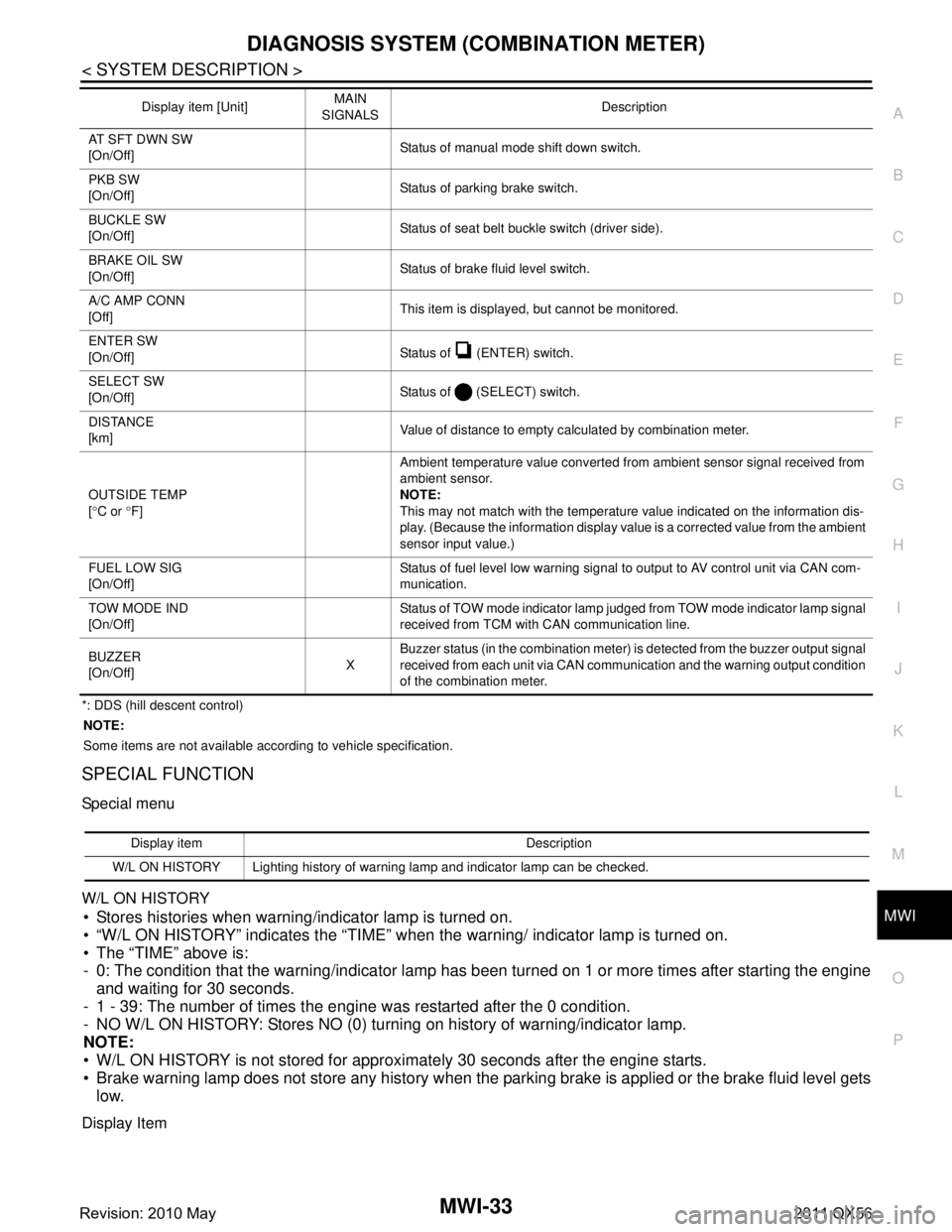
*: DDS (hill descent control) NOTE:
Some items are not available according to vehicle specification.
SPECIAL FUNCTION
Special menu
W/L ON HISTORY
Stores histories when warning/indicator lamp is turned on.
“W/L ON HISTORY” indicates the “TIME” when the warning/ indicator lamp is turned on.
The “TIME” above is:
- 0: The condition that the warning/indicator lamp has been turned on 1 or more times after starting the engine and waiting for 30 seconds.
- 1 - 39: The number of times the engine was restarted after the 0 condition.
- NO W/L ON HISTORY: Stores NO (0) turning on history of warning/indicator lamp.
NOTE:
W/L ON HISTORY is not stored for approximately 30 seconds after the engine starts.
Brake warning lamp does not store any history when the parking brake is applied or the brake fluid level gets
low.
Display Item
AT SFT DWN SW
[On/Off] Status of manual mode shift down switch.
PKB SW
[On/Off] Status of parking brake switch.
BUCKLE SW
[On/Off] Status of seat belt buckle switch (driver side).
BRAKE OIL SW
[On/Off] Status of brake fluid level switch.
A/C AMP CONN
[Off] This item is displayed, but cannot be monitored.
ENTER SW
[On/Off] Status of (ENTER) switch.
SELECT SW
[On/Off] Status of (SELECT) switch.
DISTANCE
[km] Value of distance to empty calculated by combination meter.
OUTSIDE TEMP
[ ° C or °F] Ambient temperature value converted from ambient sensor signal received from
ambient sensor.
NOTE:
This may not match with the temperature value indicated on the information dis-
play. (Because the information display value is a corrected value from the ambient
sensor input value.)
FUEL LOW SIG
[On/Off] Status of fuel level low warning signal to output to AV control unit via CAN com-
munication.
TOW MODE IND
[On/Off] Status of TOW mode indicator lamp judged from TOW mode indicator lamp signal
received from TCM with CAN communication line.
BUZZER
[On/Off] XBuzzer status (in the combination meter) is detected from the buzzer output signal
received from each unit via CAN communication and the warning output condition
of the combination meter.
Display item [Unit]
MAIN
SIGNALS Description
Display item Description
W/L ON HISTORY Lighting history of warning lamp and indicator lamp can be checked.
Revision: 2010 May2011 QX56