Page 4451 of 5598
VEHICLE HEIGHT CANNOT BE RAISEDSCS-91
< SYMPTOM DIAGNOSIS > [AIR LEVELIZER CONTROL SYSTEM]
C
D
F
G H
I
J
K L
M A
B
SCS
N
O P
SYMPTOM DIAGNOSIS
VEHICLE HEIGHT CANNOT BE RAISED
DescriptionINFOID:0000000006256092
Vehicle height remains in low status.
Diagnosis ProcedureINFOID:0000000006256093
1.CHECK APPEARANCE
Visually check for fuse, malfunction of suspension components, installation malfunction, or deformation of
vehicle height sensor.
Is the inspection result normal?
YES >> GO TO 2.
NO >> Repaire or replace damaged parts.
2.PERFORM SELF-DIAGNOSIS
1. Turn ignition switch ON.
2. Select “Self Diagnostic Result” in “E-SUS”.
Are any DTC detected?
YES >> Refer to SCS-59, "DTC Index".
NO >> GO TO 3.
3.PERFORM STANDARD VEHICLE HEIGHT SETTING
Refer to SCS-67, "
Work Procedure".
Is the symptom improved?
YES >> INSPECTION END
NO >> Replace the air levelizer control module. Refer to SCS-94, "
Removal and Installation".
Revision: 2010 May2011 QX56
Page 4452 of 5598
SCS-92
< SYMPTOM DIAGNOSIS >[AIR LEVELIZER CONTROL SYSTEM]
VEHICLE HEIGHT CANNOT BE LOWERED
VEHICLE HEIGHT CANNOT BE LOWERED
DescriptionINFOID:0000000006256094
Vehicle height remains in high status.
Diagnosis ProcedureINFOID:0000000006256095
1.CHECK APPEARANCE
Visually check for fuse, malfunction of suspension components, installation malfunction, or deformation of
vehicle height sensor.
Is the inspection result normal?
YES >> GO TO 2.
NO >> Repaire or replace damaged parts.
2.PERFORM SELF-DIAGNOSIS
1. Turn ignition switch ON.
2. Select “Self Diagnostic Result” in “E-SUS”.
Are any DTC detected?
YES >> Refer to SCS-59, "DTC Index".
NO >> GO TO 3.
3.PERFORM STANDARD VEHICLE HEIGHT SETTING
Refer to SCS-67, "
Work Procedure".
Is the symptom improved?
YES >> INSPECTION END
NO >> Replace the air levelizer control module. Refer to SCS-94, "
Removal and Installation".
Revision: 2010 May2011 QX56
Page 5002 of 5598

STEERING WHEELST-15
< BASIC INSPECTION >
C
DE
F
H I
J
K L
M A
B
ST
N
O P
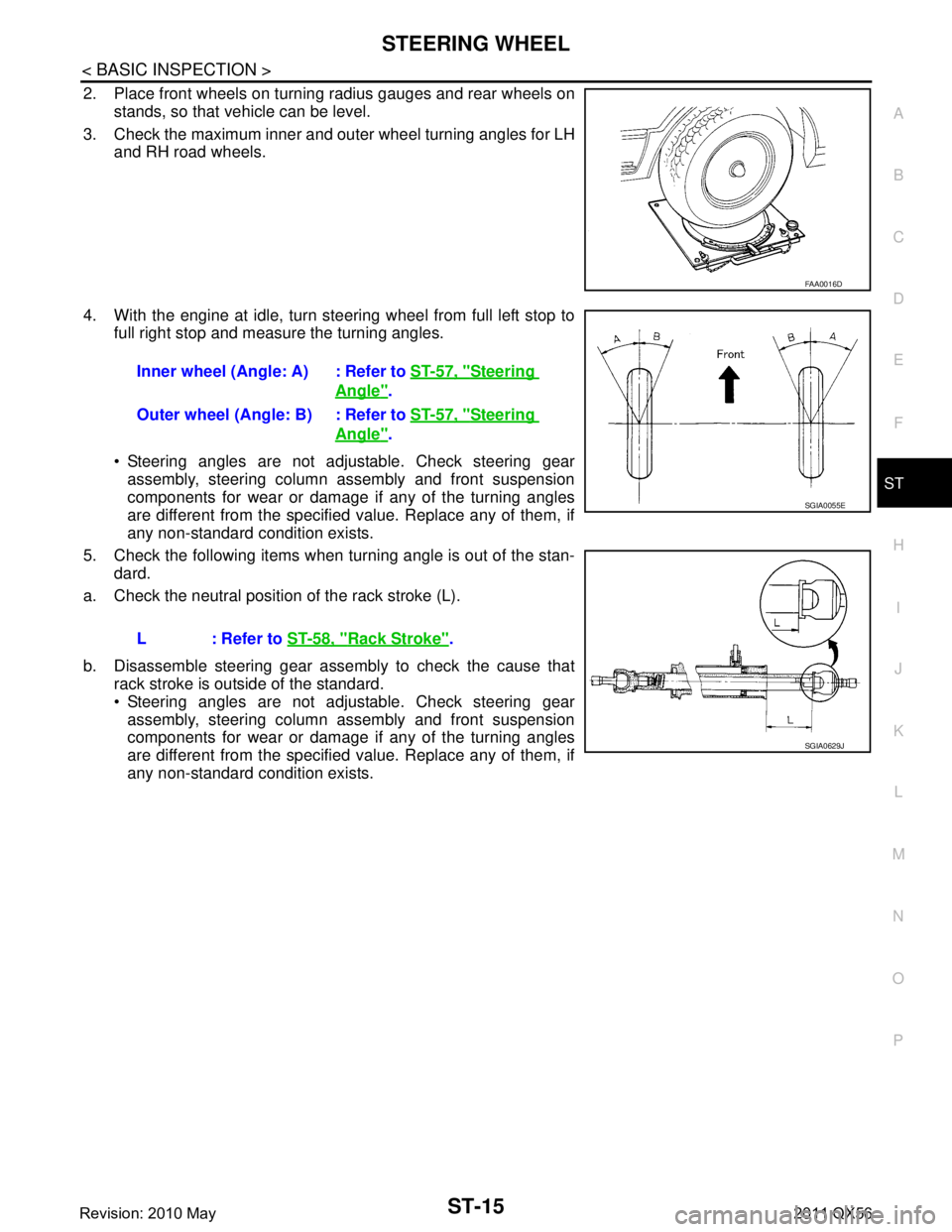
2. Place front wheels on turning radius gauges and rear wheels on stands, so that vehicle can be level.
3. Check the maximum inner and outer wheel turning angles for LH and RH road wheels.
4. With the engine at idle, turn steering wheel from full left stop to full right stop and measure the turning angles.
Steering angles are not adjustable. Check steering gear
assembly, steering column assembly and front suspension
components for wear or damage if any of the turning angles
are different from the specified value. Replace any of them, if
any non-standard condition exists.
5. Check the following items when turning angle is out of the stan- dard.
a. Check the neutral position of the rack stroke (L).
b. Disassemble steering gear assembly to check the cause that rack stroke is outside of the standard.
Steering angles are not adjustable. Check steering gear
assembly, steering column assembly and front suspension
components for wear or damage if any of the turning angles
are different from the specified value. Replace any of them, if
any non-standard condition exists.
FAA0016D
Inner wheel (Angle: A) : Refer to ST-57, "Steering
Angle".
Outer wheel (Angle: B) : Refer to ST-57, "
Steering
Angle".
L : Refer to ST-58, "
Rack Stroke".
SGIA0055E
SGIA0629J
Revision: 2010 May2011 QX56
Page 5016 of 5598

NOISE, VIBRATION AND HARSHNESS (NVH) TROUBLESHOOTINGST-29
< SYMPTOM DIAGNOSIS >
C
DE
F
H I
J
K L
M A
B
ST
N
O P
NOISE, VIBRATION AND HARSHN ESS (NVH) TROUBLESHOOTING
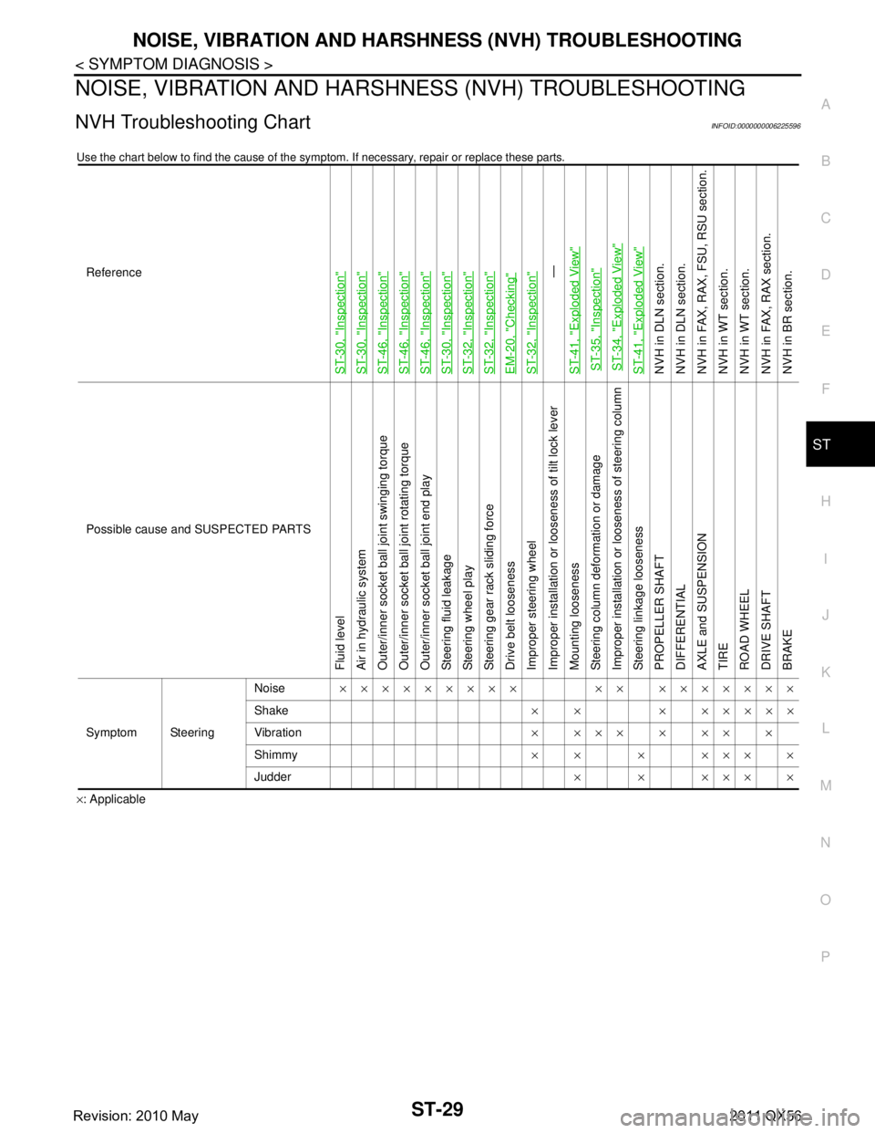
NVH Troubleshooting ChartINFOID:0000000006225596
Use the chart below to find the cause of the symp tom. If necessary, repair or replace these parts.
×: ApplicableReference
ST-30, "
Inspection
"
ST-30, "
Inspection
"
ST-46, "
Inspection
"
ST-46, "
Inspection
"
ST-46, "
Inspection
"
ST-30, "
Inspection
"
ST-32, "
Inspection
"
ST-32, "
Inspection
"
EM-20, "
Checking
"
ST-32, "
Inspection
"—
ST-41, "
Exploded View
"
ST-35, "
Inspection
"
ST-34, "
Exploded View
"
ST-41, "
Exploded View
"
NVH in DLN section.
NVH in DLN section.
NVH in FAX, RAX, FSU, RSU section.
NVH in WT section.
NVH in WT section.
NVH in FAX, RAX section.
NVH in BR section.
Possible cause and SUSPECTED PARTS
Fluid level
Air in hydraulic system
Outer/inner socket ball joint swinging torque
Outer/inner socket ball joint rotating torque
Outer/inner socket ball joint end play
Steering fluid leakage
Steering wheel play
Steering gear rack sliding force
Drive belt looseness
Improper steering wheel
Improper installation or looseness of tilt lock lever
Mounting looseness
Steering column deformation or damage
Improper installation or looseness of steering column
Steering linkage looseness
PROPELLER SHAFT
DIFFERENTIAL
AXLE and SUSPENSION
TIRE
ROAD WHEEL
DRIVE SHAFT
BRAKE
Symptom Steering Noise
××××××××× ×× ×××××××
Shake × × × ×××××
Vibration ××××××××
Shimmy ×× × ××××
Judder ××××××
Revision: 2010 May2011 QX56
Page 5019 of 5598

ST-32
< PERIODIC MAINTENANCE >
STEERING WHEEL
STEERING WHEEL
InspectionINFOID:0000000006225598
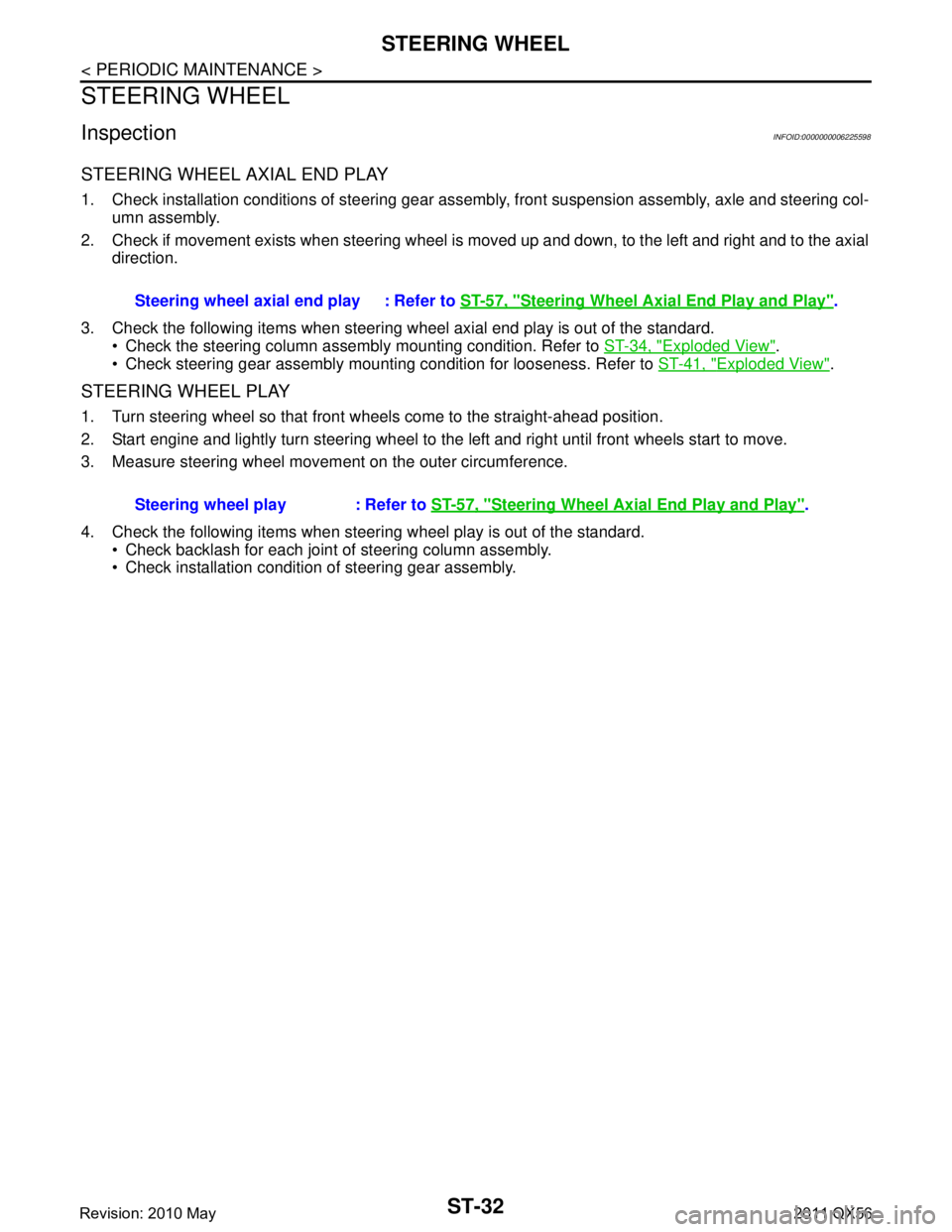
STEERING WHEEL AXIAL END PLAY
1. Check installation conditions of steering gear assembly, front suspension assembly, axle and steering col-
umn assembly.
2. Check if movement exists when steering wheel is moved up and down, to the left and right and to the axial direction.
3. Check the following items when steering w heel axial end play is out of the standard.
Check the steering column assembly mounting condition. Refer to ST-34, "
Exploded View".
Check steering gear assembly mounting condition for looseness. Refer to ST-41, "
Exploded View".
STEERING WHEEL PLAY
1. Turn steering wheel so that front wheels come to the straight-ahead position.
2. Start engine and lightly turn steering wheel to the left and right until front wheels start to move.
3. Measure steering wheel movement on the outer circumference.
4. Check the following items when steeri ng wheel play is out of the standard.
Check backlash for each joint of steering column assembly.
Check installation condition of steering gear assembly. Steering wheel axial end play : Refer to
ST-57, "
Steering Wheel Axial End Play and Play".
Steering wheel play : Refer to ST-57, "
Steering Wheel Axial End Play and Play".
Revision: 2010 May2011 QX56
Page 5293 of 5598
![INFINITI QX56 2011 Factory Service Manual
TRANSMISSION ASSEMBLYTM-205
< UNIT REMOVAL AND INSTALLATION > [7AT: RE7R01B]
C
EF
G H
I
J
K L
M A
B
TM
N
O P
UNIT REMOVAL AND INSTALLATION
TRANSMISSION ASSEMBLY
2WD
2WD : Exploded ViewINFOID:00000000 INFINITI QX56 2011 Factory Service Manual
TRANSMISSION ASSEMBLYTM-205
< UNIT REMOVAL AND INSTALLATION > [7AT: RE7R01B]
C
EF
G H
I
J
K L
M A
B
TM
N
O P
UNIT REMOVAL AND INSTALLATION
TRANSMISSION ASSEMBLY
2WD
2WD : Exploded ViewINFOID:00000000](/manual-img/42/57033/w960_57033-5292.png)
TRANSMISSION ASSEMBLYTM-205
< UNIT REMOVAL AND INSTALLATION > [7AT: RE7R01B]
C
EF
G H
I
J
K L
M A
B
TM
N
O P
UNIT REMOVAL AND INSTALLATION
TRANSMISSION ASSEMBLY
2WD
2WD : Exploded ViewINFOID:0000000006233263
2WD : Removal and InstallationINFOID:0000000006233264
REMOVAL
CAUTION:
When removing the A/T assembly from engine, fi rst remove the crankshaft position sensor (POS)
from the A/T assembly.
Be careful not to damage sensor edge.
1. Shift the selector lever to “P” position, and release the parking brake.
2. Disconnect the battery cabl e from the negative terminal.
3. Support A/T assembly with a transmission jack. CAUTION:
When setting the transmission jack, be careful not to allow it to collide against the drain plug and
overflow plug.
4. Remove rear engine mounting cross member.
5. Remove engine mounting insulator (rear).
6. Remove control cable from A/T assembly. Refer to TM-178, "
Removal and Installation".
7. Disconnect heated oxygen sensor 2 connectors (bank 1 and bank 2). Refer to EX-5, "
Exploded View".
1. A/T assembly 2. Front suspension rear cross mem-
ber3. Rear engine mounting cross
member
4. Engine mounting insulator (rear)
A. Tightening must be done following the installation procedure. Refer to TM-205, "
2WD : Removal and Installation".
Refer to GI-4, "
Components" for symbols in the figure.
JSDIA1856GB
Revision: 2010 May2011 QX56
Page 5294 of 5598
![INFINITI QX56 2011 Factory Service Manual
TM-206
< UNIT REMOVAL AND INSTALLATION >[7AT: RE7R01B]
TRANSMISSION ASSEMBLY
8. Remove exhaust front tube (RH and LH) and main muffler. Refer to
EX-5, "Exploded View".
9. Separate propeller shaft as INFINITI QX56 2011 Factory Service Manual
TM-206
< UNIT REMOVAL AND INSTALLATION >[7AT: RE7R01B]
TRANSMISSION ASSEMBLY
8. Remove exhaust front tube (RH and LH) and main muffler. Refer to
EX-5, "Exploded View".
9. Separate propeller shaft as](/manual-img/42/57033/w960_57033-5293.png)
TM-206
< UNIT REMOVAL AND INSTALLATION >[7AT: RE7R01B]
TRANSMISSION ASSEMBLY
8. Remove exhaust front tube (RH and LH) and main muffler. Refer to
EX-5, "Exploded View".
9. Separate propeller shaft assembly. Refer to DLN-144, "
Removal and Installation".
NOTE:
Cap or plug opening to prevent fluid from spilling.
10. Remove front under cover with a power tool. Refer to EXT-25, "
Removal and Installation".
11. Remove protector A and B. Refer to SCS-32, "
FRONT TUBE ASSEMBLY : Exploded View".
12. Remove front suspension rear cross member.
13. Remove crankshaft position sensor (POS) from A/T assembly. Refer to EM-106, "
Exploded View".
CAUTION:
Never subject it to impact by dropping or hitting it.
Never disassemble.
Never allow metal filings, etc. to ge t on the sensor's front edge magnetic area.
Never place in an area affected by magnetism.
14. Remove rear plate cover. Refer to EM-54, "
Exploded View".
15. Turn crankshaft, and remove the four tight ening bolts for drive plate and torque converter.
CAUTION:
When turning the crankshaft, turn it clockw ise as viewed from the front of the engine.
16. Remove A/T fluid cooler tube A and D. Refer to TM-202, "
Exploded View".
NOTE:
Cap or plug openings to prevent fluid from spilling.
17. Remove bolts fixing A/T assembly to engine with a power tool.
18. Disconnect connector from A/T assembly.
19. Remove harness and brackets from A/T assembly.
20. Remove A/T assembly from the vehicle. CAUTION:
Secure torque converter to prevent it from dropping.
Secure A/T assembly to a transmission jack.
21. Remove air breather hose and bracket. Refer to TM-199, "
2WD
: Exploded View".
22. Remove manual lever from A/T assembly. Refer to TM-178,
"Exploded View".
INSTALLATION
Note the following, and Install in the reverse order of removal.
Check fitting of dowel pin ( ).
ATA0025D
JSDIA1597ZZ
Revision: 2010 May2011 QX56
Page 5296 of 5598
![INFINITI QX56 2011 Factory Service Manual
TM-208
< UNIT REMOVAL AND INSTALLATION >[7AT: RE7R01B]
TRANSMISSION ASSEMBLY
4WD : Exploded View
INFOID:0000000006226910
4WD : Removal and InstallationINFOID:0000000006226911
REMOVAL
CAUTION:
When INFINITI QX56 2011 Factory Service Manual
TM-208
< UNIT REMOVAL AND INSTALLATION >[7AT: RE7R01B]
TRANSMISSION ASSEMBLY
4WD : Exploded View
INFOID:0000000006226910
4WD : Removal and InstallationINFOID:0000000006226911
REMOVAL
CAUTION:
When](/manual-img/42/57033/w960_57033-5295.png)
TM-208
< UNIT REMOVAL AND INSTALLATION >[7AT: RE7R01B]
TRANSMISSION ASSEMBLY
4WD : Exploded View
INFOID:0000000006226910
4WD : Removal and InstallationINFOID:0000000006226911
REMOVAL
CAUTION:
When removing the A/T assembly from engine, fi rst remove the crankshaft position sensor (POS)
from the A/T assembly.
Be careful not to damage sensor edge.
1. Shift the selector lever to “P” pos ition, and release the parking brake.
2. Disconnect the battery cable from the negative terminal.
3. Remove control cable from A/T assembly. Refer to TM-178, "
Removal and Installation".
4. Disconnect heated oxygen sensor 2 connectors (bank 1 and bank 2). Refer to EX-5, "
Exploded View".
5. Remove exhaust front tube (RH and LH) and main muffler. Refer to EX-5, "
Exploded View".
6. Support A/T assembly with a transmission jack. CAUTION:
When setting the transmission jack, be careful not to allow it to collide against the drain plug and
overflow plug.
7. Remove rear engine mounting cross member and engine mounting insulator (rear).
8. Separate propeller shaft assembly (front). Refer to DLN-129, "
Removal and Installation".
9. Separate propeller shaft assembly (rear). Refer to DLN-137, "
Removal and Installation".
10. Remove front under cover with a power tool. Refer to EXT-25, "
Removal and Installation".
11. Remove front suspension rear cross member.
1. A/T assembly 2. Front suspension rear cross mem- ber3. Rear engine mounting cross
member
4. Engine mounting insulator (rear)
A. Tightening must be done following the installation procedure. Refer to TM-208, "
4WD : Removal and Installation".
Refer to GI-4, "
Components" for symbols in the figure.
JPDIA1156GB
Revision: 2010 May2011 QX56