2011 INFINITI QX56 light
[x] Cancel search: lightPage 1504 of 5598

DEF-12
< SYSTEM DESCRIPTION >
DIAGNOSIS SYSTEM (IPDM E/R)
CONSULT-III Function (IPDM E/R)
INFOID:0000000006349777
APPLICATION ITEM
CONSULT-III performs the following functions via CAN communication with IPDM E/R.
SELF DIAGNOSTIC RESULT
Refer to PCS-22, "DTCIndex".
DATA MONITOR
Monitor item
Oil pressure warning lamp does not operate Perform auto active test.
Does the oil pressure warning
lamp blink?YES
Harness or connector be-
tween IPDM E/R and oil
pressure switch
Oil pressure switch
IPDM E/R
NO CAN communication signal
between IPDM E/R and
BCM
CAN communication signal
between BCM and combi-
nation meter
Combination meter
Symptom Inspection contents Possible cause
Diagnosis mode Description
Ecu Identification Allows confirmation of IPDM E/R part number.
Self Diagnostic Result Displays the diagnosis results judged by IPDM E/R.
Data Monitor Displays the real-time input/output data from IPDM E/R input/output data.
Active Test IPDM E/R can provide a drive signal to electronic components to check their operations.
CAN Diag Support Monitor The results of transmit/receive diagnosis of CAN communication can be read.
Monitor Item [Unit] MAIN SIG-
NALS Description
RAD FAN REQ
[1/2/3/4] ×Displays the value of the cooling fan speed request signal received from ECM via
CAN communication.
AC COMP REQ
[Off/On] ×Displays the status of the A/C compressor request signal received from ECM via
CAN communication.
TA I L & C L R R E Q
[Off/On] ×
Displays the status of the position light request signal received from BCM via CAN
communication.
HL LO REQ
[Off/On] ×Displays the status of the low beam request signal received from BCM via CAN
communication.
HL HI REQ
[Off/On] ×Displays the status of the high beam request signal received from BCM via CAN
communication.
FR FOG REQ
[Off/On] ×Displays the status of the front fog light request signal received from BCM via
CAN communication.
FR WIP REQ
[Stop/1LOW/Low/Hi] ×
Displays the status of the front wiper request signal received from BCM via CAN
communication.
WIP AUTO STOP
[STOP P/ACT P] ×
Displays the status of the front wiper auto stop signal judged by IPDM E/R.
WIP PROT
[Off/BLOCK] ×
Displays the status of the front wiper fail-safe operation judged by IPDM E/R.
IGN RLY1 -REQ
[Off/On] Displays the status of the ignition switch ON signal received from BCM via CAN
communication.
IGN RLY
[Off/On] ×
Displays the status of the ignition relay judged by IPDM E/R.
Revision: 2010 May2011 QX56
Page 1536 of 5598

DEF-44
< REMOVAL AND INSTALLATION >
FILAMENT
Ruler 30 cm (11.8 in) long
Drawing pen
Heat gun
Alcohol
Cloth
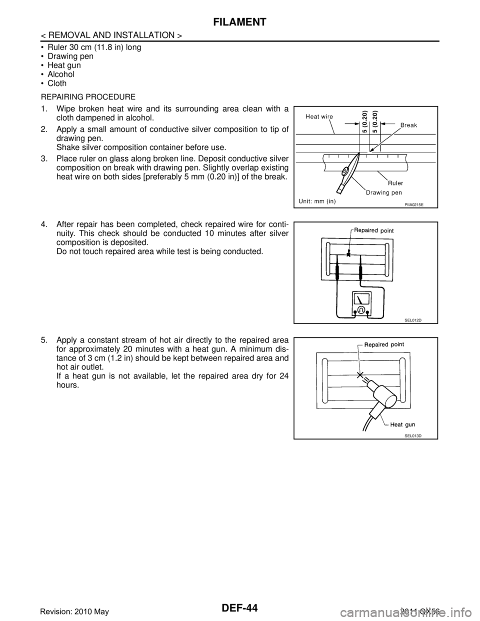
REPAIRING PROCEDURE
1. Wipe broken heat wire and its surrounding area clean with acloth dampened in alcohol.
2. Apply a small amount of conductive silver composition to tip of
drawing pen.
Shake silver composition container before use.
3. Place ruler on glass along broken line. Deposit conductive silver composition on break with drawing pen. Slightly overlap existing
heat wire on both sides [preferably 5 mm (0.20 in)] of the break.
4. After repair has been completed, check repaired wire for conti- nuity. This check should be conducted 10 minutes after silver
composition is deposited.
Do not touch repaired area while test is being conducted.
5. Apply a constant stream of hot air directly to the repaired area for approximately 20 minutes with a heat gun. A minimum dis-
tance of 3 cm (1.2 in) should be kept between repaired area and
hot air outlet.
If a heat gun is not available, let the repaired area dry for 24
hours.
PIIA0215E
SEL012D
SEL013D
Revision: 2010 May2011 QX56
Page 1537 of 5598

DLK-1
BODY EXTERIOR, DOORS, ROOF & VEHICLE SECURITY
C
D
E
F
G H
I
J
L
M
SECTION DLK
A
B
DLK
N
O P
CONTENTS
DOOR & LOCK
PRECAUTION ................ ...............................8
PRECAUTIONS .............................................. .....8
Precaution for Supplemental Restraint System
(SRS) "AIR BAG" and "SEAT BELT PRE-TEN-
SIONER" ............................................................. ......
8
Precaution Necessary for Steering Wheel Rota-
tion after Battery Disconnect .....................................
8
Precautions For Xenon Headlamp Service ...............9
Work ..........................................................................9
PREPARATION ...........................................10
PREPARATION .............................................. ....10
Commercial Service Tools .................................. ....10
SYSTEM DESCRIPTION .............................11
COMPONENT PARTS ................................... ....11
DOOR LOCK SYSTEM .............................................11
DOOR LOCK SYSTEM :
Component Parts Location ................................ ....
11
DOOR LOCK SYSTEM : Component Description ....12
AUTOMATIC BACK DOOR SYSTEM .......................13
AUTOMATIC BACK DOOR SYSTEM :
Component Parts Location ................................ ....
14
AUTOMATIC BACK DOOR SYSTEM :
Component Description ..........................................
15
SYSTEM (POWER DOOR LOCK SYSTEM) .....16
System Diagram .................................................. ....16
System Description .................................................16
SYSTEM (INTELLIGENT KEY SYSTEM) ..........18
INTELLIGENT KEY SYSTEM ...................................18
INTELLIGENT KEY SYSTEM : System Diagram ....18
INTELLIGENT KEY SYSTEM : System Descrip-
tion ..........................................................................
18
DOOR LOCK FUNCTION ...................................... ....19
DOOR LOCK FUNCTION : System Diagram ..........19
DOOR LOCK FUNCTION : System Description .....19
BACK DOOR OPEN FUNCTION ........................... ....21
BACK DOOR OPEN FUNCTION : System Dia-
gram ........................................................................
21
BACK DOOR OPEN FUNCTION : System De-
scription ...................................................................
21
REMOTE KEYLESS ENTRY FUNCTION ..................23
REMOTE KEYLESS ENTRY FUNCTION : Sys-
tem Diagram ........................................................ ....
23
REMOTE KEYLESS ENTRY FUNCTION : Sys-
tem Description ........................................................
23
KEY REMINDER FUNCTION ................................ ....25
KEY REMINDER FUNCTION : System Diagram ....25
KEY REMINDER FUNCTION : System Descrip-
tion ...........................................................................
26
WELCOME LIGHT FUNCTION ............................. ....26
WELCOME LIGHT FUNCTION : System Diagram
....
26
WELCOME LIGHT FUNCTION : System Descrip-
tion ...........................................................................
26
WARNING FUNCTION .......................................... ....27
WARNING FUNCTION : System Description ..........27
SYSTEM (AUTOMATIC BACK DOOR SYS-
TEM) ..................................................................
31
System Diagram .................................................. ....31
System Description ..................................................31
SYSTEM (INTEGRATED HOMELINK
TRANSMITTER) ................................................
37
System Description .............................................. ....37
DIAGNOSIS SYSTEM (BCM) ...........................38
COMMON ITEM ..................................................... ....38
COMMON ITEM : CONSULT-III Function (BCM -
COMMON ITEM) .....................................................
38
Revision: 2010 May2011 QX56
Page 1541 of 5598

DLK-5
C
DE
F
G H
I
J
L
M A
B
DLK
N
O P
FUEL LID LOCK ACTUATOR DOES NOT OP-
ERATE ............................................................ ..
176
Diagnosis Procedure ........................................... ..176
IGNITION POSITION WARNING FUNCTION
DOES NOT OPERATE .....................................
177
Diagnosis Procedure ........................................... ..177
SELECTIVE UNLOCK FUNCTION DOES
NOT OPERATE ................................................
178
Diagnosis Procedure ........................................... ..178
AUTO DOOR LOCK OPERATION DOES NOT
OPERATE .........................................................
179
Diagnosis Procedure ........................................... ..179
VEHICLE SPEED SENSING AUTO LOCK
OPERATION DOES NOT OPERATE ..............
180
Diagnosis Procedure ........................................... ..180
IGN OFF INTERLOCK DOOR UNLOCK
FUNCTION DOES NOT OPERATE .................
181
Diagnosis Procedure ........................................... ..181
P RANGE INTERLOCK DOOR LOCK/UN-
LOCK FUNCTION DOES NOT OPERATE ......
182
Diagnosis Procedure ........................................... ..182
HAZARD AND HORN REMINDER DOES
NOT OPERATE ................................................
183
Diagnosis Procedure ........................................... ..183
HAZARD AND BUZZER REMINDER DOES
NOT OPERATE ................................................
184
Diagnosis Procedure ........................................... ..184
KEY REMINDER FUNCTION DOES NOT OP-
ERATE ..............................................................
185
Diagnosis Procedure ........................................... ..185
WELCOME LIGHT FUNCTION DOES NOT
OPERATE .........................................................
186
Diagnosis Procedure ........................................... ..186
OFF POSITION WARNING DOES NOT OP-
ERATE ..............................................................
188
Diagnosis Procedure ........................................... ..188
P POSITION WARNING DOES NOT OPER-
ATE ...................................................................
189
Description .......................................................... ..189
Diagnosis Procedure .............................................189
ACC WARNING DOES NOT OPERATE .........191
Description .......................................................... ..191
Diagnosis Procedure .............................................191
TAKE AWAY WARNING DOES NOT OPER-
ATE ...................................................................
192
Description .......................................................... ..192
Diagnosis Procedure .............................................192
KEY ID WARNING DOES NOT OPERATE ....194
Description ........................................................... ..194
Diagnosis Procedure .............................................194
INTELLIGENT KEY LOW BATTERY WARN-
ING DOES NOT OPERATE ............................
195
Description .............................................................195
Diagnosis Procedure .............................................195
DOOR LOCK OPERATION WARNING DOES
NOT OPERATE ...............................................
197
Diagnosis Procedure .............................................197
AUTOMATIC BACK DOOR OPERATION
DOES NOT OPERATE ....................................
198
ALL SWITCHES ..................................................... ..198
ALL SWITCHES : Description ...............................198
ALL SWITCHES : Diagnosis Procedure ................198
AUTOMATIC BACK DOOR SWITCH .................... ..199
AUTOMATIC BACK DOOR SWITCH : Descrip-
tion .........................................................................
199
AUTOMATIC BACK DOOR SWITCH : Diagnosis
Procedure ..............................................................
199
AUTOMATIC BACK DOOR CLOSE SWITCH ........199
AUTOMATIC BACK DOOR CLOSE SWITCH :
Description ........................................................... ..
199
AUTOMATIC BACK DOOR CLOSE SWITCH : Di-
agnosis Procedure .................................................
199
INTELLIGENT KEY ................................................ ..200
INTELLIGENT KEY : Description ..........................200
INTELLIGENT KEY : Diagnosis Procedure ......... ..200
BACK DOOR OPENER SWITCH .......................... ..200
BACK DOOR OPENER SWITCH : Description .....200
BACK DOOR OPENER SWITCH : Diagnosis Pro-
cedure ....................................................................
200
OPEN/CLOSURE FUNCTION ............................... ..201
OPEN/CLOSURE FUNCTION : Description .........201
OPEN/CLOSURE FUNCTION : Diagnosis Proce-
dure .......................................................................
201
OPEN FUNCTION .................................................. ..202
OPEN FUNCTION : Description ............................202
OPEN FUNCTION : Diagnosis Procedure ............202
CLOSURE FUNCTION .......................................... ..202
CLOSURE FUNCTION : Description .....................202
CLOSURE FUNCTION : Diagnosis Procedure .....203
AUTOMATIC BACK DOOR WARNING DOES
NOT OPERATE ...............................................
204
BUZZER ................................................................. ..204
BUZZER : Description ...........................................204
BUZZER : Diagnosis Procedure ............................204
HAZARD WARNING LAMP ................................... ..204
HAZARD WARNING LAMP : Description ..............204
Revision: 2010 May2011 QX56
Page 1555 of 5598

SYSTEM (INTELLIGENT KEY SYSTEM)
DLK-19
< SYSTEM DESCRIPTION >
C
D E
F
G H
I
J
L
M A
B
DLK
N
O P
DOOR LOCK FUNCTION
DOOR LOCK FUNCTION : System DiagramINFOID:0000000006225841
DOOR LOCK FUNCTION : System DescriptionINFOID:0000000006225842
Only when pressing the door request switch, it is possi ble to lock and unlock the door by carrying the Intelli-
gent Key.
OPERATION DESCRIPTION
When the BCM detects that each door request switch is pressed, it activates the outside key antenna and
inside key antenna corresponding to the pressed door reques t switch and transmits the request signal to the
Intelligent Key. And then, check that the Intelligent Key is near the door.
If the Intelligent Key is within the outside key ant enna detection area, it receives the request signal and
transmits the key ID signal to the BCM via remote keyless entry receiver.
BCM receives the key ID signal and compares it with the registered key ID.
BCM locks/unlocks each doors (except back door).
BCM sounds Intelligent Key warning buzzer (lock: 2 ti mes, unlock: 1 time) and blinks hazard warning lamps
(lock: 2 times, unlock: 1 time) at the same time as a reminder.
Key reminder The key reminder buzzer sounds a warning if the door is locked with the key left
inside the vehicle DLK-26
Welcome lightWhen the Intelligent Key is carried, and vehicle doors are approached, the BCM
illuminates interior room lamps and operates heart beat operation of the push-
button ignition switch DLK-26
Warning
If an action that does not meet the operating condition of the Intelligent Key sys-
tem is taken, the buzzer sounds to inform the driver DLK-27
Engine start The engine can be turned on while carrying the Intelligent Key
SEC-12
Interior room lamp control Interior room lamp is controlled according to door lock/unlock state INL-6
Power window Power window can be operated by Intelligent Key button operationPWC-8
Automatic drive positioner Automatic drive positioner system can be operated by door unlock operationADP-11
Panic alarm When Intelligent Key panic alarm button is pressed, horn soundsSEC-18
Function Description Refer
JMKIA5068GB
Revision: 2010 May2011 QX56
Page 1562 of 5598

DLK-26
< SYSTEM DESCRIPTION >
SYSTEM (INTELLIGENT KEY SYSTEM)
KEY REMINDER FUNCTION : System Description
INFOID:0000000006225848
Key reminder is the function that prevents the key from being left in the vehicle.
Key reminder has the following 3 functions.
*: If the door closing impact shocks the door lock knob, or contacts against baggage with the door lock knob might activate the door locks
accidentally but unlock operation is perform in these cases.
CAUTION:
The above function operates when the Intelligent Key is inside the vehicle. However, there may be
times when the Intelligent Key cannot be detected, and this function does not operate when the Intel-
ligent Key is on the instrument panel, rear parcel shelf, or in the glove box. Also, this system some-
times does not operate if the Intelligent Key is in the door pocket for the open door.
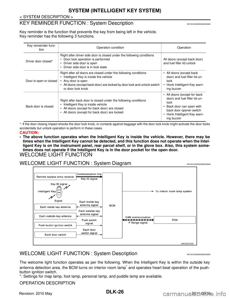
WELCOME LIGHT FUNCTION
WELCOME LIGHT FUNCTION : System DiagramINFOID:0000000006225849
WELCOME LIGHT FUNCTION : System DescriptionINFOID:0000000006225850
The welcome light function operates as per the following. When the Intelligent Key is within the outside key
antenna detection area, the BCM turns on interior room lamp
* and operates heart beat operation of the push-
button ignition switch.
*: Settings for map lamp, foot lamp, personal lamp, and puddle lamp are available.
OPERATION DESCRIPTION
Key remainder func-
tion Operation condition Operation
Driver door closed* Right after driver side door is closed under the following conditions
Door lock operation is performed
Driver side door is open
Driver side door is in lock state All doors (except back door)
and fuel filler lid unlock
Door is open or closed Right after all doors are closed under the following conditions
Intelligent Key is inside the vehicle
Any door is open
All doors (except back door) are locked by door lock and unlock switch
or door lock knob All doors (except back
door) and fuel filler lid un-
lock
Honk Intelligent Key warn- ing buzzer
Back door is closed Right after back door is closed under the following conditions
Intelligent Key is inside vehicle
All doors (except for back door) are closed
All doors (except for back door) are locked All doors (except for back
door) and fuel filler lid un-
lock
Back door can open with back door opener switch
Honk Intelligent Key warn-
ing buzzer
JMKIA5072GB
Revision: 2010 May2011 QX56
Page 1563 of 5598

SYSTEM (INTELLIGENT KEY SYSTEM)
DLK-27
< SYSTEM DESCRIPTION >
C
D E
F
G H
I
J
L
M A
B
DLK
N
O P
When the BCM detects that the Intelligent Key is within the outside key antenna detection area. BCM trans-
mits the request signal to the Intelligent Key and check it is near the door.
Intelligent Key receives the request signal and transmits the key ID signal to the BCM via remote keyless
entry receiver.
BCM receives the key ID signal and compares it with the registered key ID.
BCM illuminates lamps that are set, when key ID verification is OK.
TIMER FUNCTION
BCM can operate welcome light function, using the timer function, for 9 days, after key switch is turned OFF.
The timer function resets when the engine is started
*.Operating period of timer function may differ depending
on battery size.
*: Timer function does not stop if another Intelligent Key that has a different key ID is detected within the inte-
rior antenna detection area, when starting the engine.
OPERATION CONDITION
If the following condition are satisfi ed, welcome light function is operated.
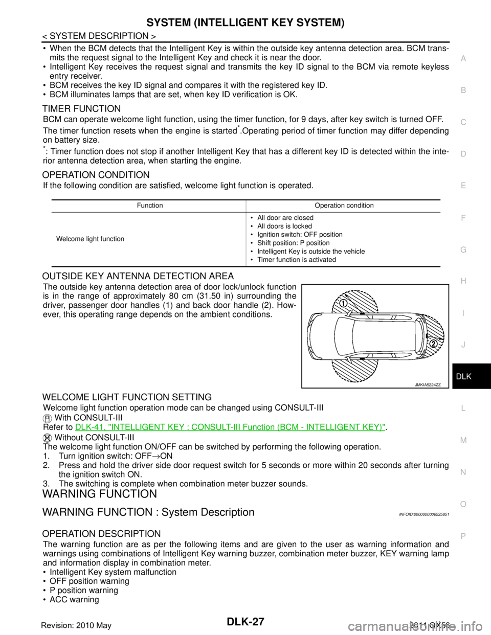
OUTSIDE KEY ANTENNA DETECTION AREA
The outside key antenna detection area of door lock/unlock function
is in the range of approximately 80 cm (31.50 in) surrounding the
driver, passenger door handles (1) and back door handle (2). How-
ever, this operating range depends on the ambient conditions.
WELCOME LIGHT FUNCTION SETTING
Welcome light function operation mode can be changed using CONSULT-III
With CONSULT-III
Refer to DLK-41, "
INTELLIGENT KEY : CONSULT-III F unction (BCM - INTELLIGENT KEY)".
Without CONSULT-III
The welcome light function ON/OFF can be s witched by performing the following operation.
1. Turn ignition switch: OFF →ON
2. Press and hold the driver side door request switch for 5 seconds or more within 20 seconds after turning the ignition switch ON.
3. The switching is complete when combination meter buzzer sounds.
WARNING FUNCTION
WARNING FUNCTION : System DescriptionINFOID:0000000006225851
OPERATION DESCRIPTION
The warning function are as per the following items and are given to the user as warning information and
warnings using combinations of Intelligent Key warning buzzer, combination meter buzzer, KEY warning lamp
and information display in combination meter.
Intelligent Key system malfunction
OFF position warning
P position warning
ACC warning
Function Operation condition
Welcome light function All door are closed
All doors is locked
Ignition switch: OFF position
Shift position: P position
Intelligent Key is outside the vehicle
Timer function is activated
JMKIA5224ZZ
Revision: 2010 May2011 QX56
Page 1578 of 5598

DLK-42
< SYSTEM DESCRIPTION >
DIAGNOSIS SYSTEM (BCM)
SELF-DIAG RESULT
Refer to BCS-57, "DTCIndex".
DATA MONITOR
AUTO LOCK SET Auto door lock operation time can be changed in this mode
MODE 1: OFF
MODE 2: 30 sec
MODE 3: 1 minute
MODE 4: 2 minutes
MODE 5: 3 minutes
MODE 6: 4 minutes
MODE 7: 5 minutes
HORN WITH KEYLESS LOCK Horn reminder function mode by Intelligent Key button can be selected from the following with
this mode
On: Operate
Off: Non-operation
PW DOWN SET Unlock button pressing time on Intelligent Key button can be selected from the following with
this mode
MODE 1: 3 sec
MODE 2: Non-operation
MODE 3: 5 sec
WELCOME LIGHT SELECT Welcome light function mode can be selected from the following with this mode
Puddle/Outside Handle
Room lamp
Head & Tail Lamps (this item is displayed, but cannot be used)
Heart Beat
WELCOME LIGHT OP SET Welcome light function mode can be changed to operation with this mode
On: Operate
Off: Non-operation
Monitor item Description
Monitor Item Condition
REQ SW -DR Indicates [On/Off] condition of door request switch (driver side)
REQ SW -AS Indicates [On/Off] condition of door request switch (passenger side)
REQ SW -BD/TR Indicates [On/Off] condition of back door request switch
PUSH SW Indicates [On/Off] condition of push-button ignition switch
CLUTCH SW NOTE:
This item is displayed, but cannot be monitored
BRAKE SW 1 Indicates [On/Off]* condition of stop lamp switch power supply
BRAKE SW 2 Indicates [On/Off] condition of stop lamp switch
DETE/CANCL SW Indicates [On/Off] condition of P position
SFT PN/N SW Indicates [On/Off] condition of P or N position
S/L -LOCK Indicates [On/Off] condition of steering lock unit (LOCK)
S/L -UNLOCK Indicates [On/Off] condition of steering lock unit (UNLOCK)
S/L RELAY -F/B Indicates [On/Off] condition of steering lock relay
UNLK SEN -DR Indicates [On/Off] condition of driver door UNLOCK status
PUSH SW -IPDM Indicates [On/Off] condition of push-button ignition switch
IGN RLY1 -F/B Indicates [On/Off] condition of ignition relay 1
DETE SW -IPDM Indicates [On/Off] condition of P position
SFT PN -IPDM Indicates [On/Off] condition of P or N position
SFT P -MET Indicates [On/Off] condition of P position
SFT N -MET Indicates [On/Off] condition of N position
ENGINE STATE Indicates [Stop/Stall/Crank/Run] condition of engine states
Revision: 2010 May2011 QX56