2011 INFINITI QX56 low oil pressure
[x] Cancel search: low oil pressurePage 3661 of 5598
![INFINITI QX56 2011 Factory Service Manual
LU-8
< PERIODIC MAINTENANCE >
ENGINE OIL
5. Install the oil pressure gauge [SST: ST25051001 (J25695-1)] (A)and hose [SST: ST25052000 (J25695-2)] (B).
6. Start the engine and warm it up to normal oper INFINITI QX56 2011 Factory Service Manual
LU-8
< PERIODIC MAINTENANCE >
ENGINE OIL
5. Install the oil pressure gauge [SST: ST25051001 (J25695-1)] (A)and hose [SST: ST25052000 (J25695-2)] (B).
6. Start the engine and warm it up to normal oper](/manual-img/42/57033/w960_57033-3660.png)
LU-8
< PERIODIC MAINTENANCE >
ENGINE OIL
5. Install the oil pressure gauge [SST: ST25051001 (J25695-1)] (A)and hose [SST: ST25052000 (J25695-2)] (B).
6. Start the engine and warm it up to normal operating temperature.
7. Check the engine oil pressure with engine running under no-load. Refer to LU-17, "
EngineOilPressure".
CAUTION:
If the difference is extreme, check the oil passages and oil pump for leaks and blockages.
8. After the inspections, install oil pressure switch as follows:
a. Remove old liquid gasket adhering to oil pressure switch and engine.
b. Apply liquid gasket and tighten oil pressure switch to the specification. Use Genuine RTV Silicone Seal ant or equivalent. Refer to GI-22, "
Recommended Chemical Prod-
ucts and Sealants".
c. After warming up engine, make sure there is no leakage of engine oil with engine running.
DrainingINFOID:0000000006289617
WARNING:
Be careful not to burn yourself, as th e engine and engine oil may be hot.
Prolonged and repeated contact with used engine oil may cause skin cancer; try to avoid direct skin
contact with used oil. If skin contact is made, wash thoroughly with soap or hand cleaner as soon as
possible.
1. Warm up the engine, and check for any oil leaks.
2. Stop the engine and wait for at least 10 minutes.
3. Remove drain plug and oil filler cap to drain the old oil.
RefillingINFOID:0000000006289618
1. Install drain plug with new washer. CAUTION:
Be sure to clean drain plug and install with new washer.
2. Refill with new engine oil. Engine oil specification and viscosity:
Refer to MA-10, "
Fluids and Lubricants".
CAUTION:
The refill capacity depends on the engine oi l temperature and drain time. Use these specifica-
tions for reference only.
Always use oil level gauge to determine the proper amount of engine oil in engine.
3. Warm up the engine and check area around drain plug and oil filter for engine oil leakage.
4. Stop the engine and wait for 10 minutes.
5. Check the engine oil level. Refer to LU-7, "
Inspection".
JPBIA0074ZZ
Oil pressure switch torque : Refer to EM-57, "Exploded View".
Tightening torque : Refer to EM-54, "
Exploded View".
Engine oil capacity : Refer to LU-17, "
Periodical Maintenance Specification".
Revision: 2010 May2011 QX56
Page 3662 of 5598
OIL FILTERLU-9
< PERIODIC MAINTENANCE >
C
DE
F
G H
I
J
K L
M A
LU
NP
O
OIL FILTER
Removal and InstallationINFOID:0000000006289619
REMOVAL
1. Remove front under cover.
2. Drain engine oil. Refer to
LU-8, "
Draining".
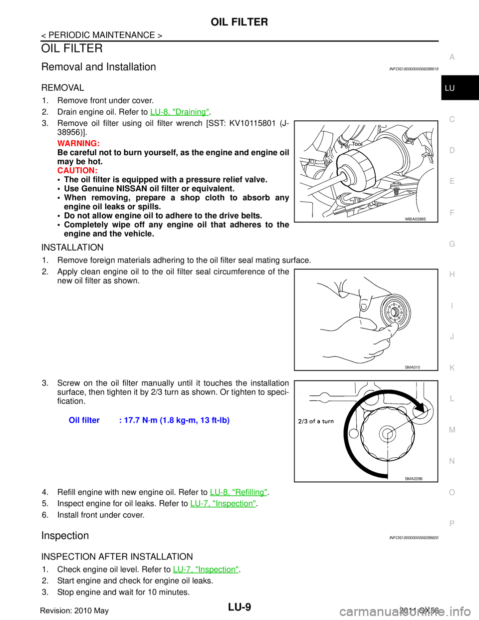
3. Remove oil filter using oil filter wrench [SST: KV10115801 (J- 38956)].
WARNING:
Be careful not to burn yourself, as the engine and engine oil
may be hot.
CAUTION:
The oil filter is equipped with a pressure relief valve.
Use Genuine NISSAN oil filter or equivalent.
When removing, prepare a s hop cloth to absorb any
engine oil leaks or spills.
Do not allow engine oil to adhere to the drive belts.
Completely wipe off any engine oil that adheres to the engine and the vehicle.
INSTALLATION
1. Remove foreign materials adhering to the oil filter seal mating surface.
2. Apply clean engine oil to the oil filter seal circumference of the
new oil filter as shown.
3. Screw on the oil filter manually until it touches the installation surface, then tighten it by 2/3 turn as shown. Or tighten to speci-
fication.
4. Refill engine with new engine oil. Refer to LU-8, "
Refilling".
5. Inspect engine for oil leaks. Refer to LU-7, "
Inspection".
6. Install front under cover.
InspectionINFOID:0000000006289620
INSPECTION AFTER INSTALLATION
1. Check engine oil level. Refer to LU-7, "Inspection".
2. Start engine and check for engine oil leaks.
3. Stop engine and wait for 10 minutes.
WBIA0388E
SMA010
Oil filter : 17.7 N·m (1.8 kg-m, 13 ft-lb)
SMA229B
Revision: 2010 May2011 QX56
Page 3670 of 5598
SERVICE DATA AND SPECIFICATIONS (SDS)
LU-17
< SERVICE DATA AND SPECIFICATIONS (SDS)
C
D E
F
G H
I
J
K L
M A
LU
NP
O
SERVICE DATA AND SPECIFICATIONS (SDS)
SERVICE DATA AND SPECIFICATIONS (SDS)
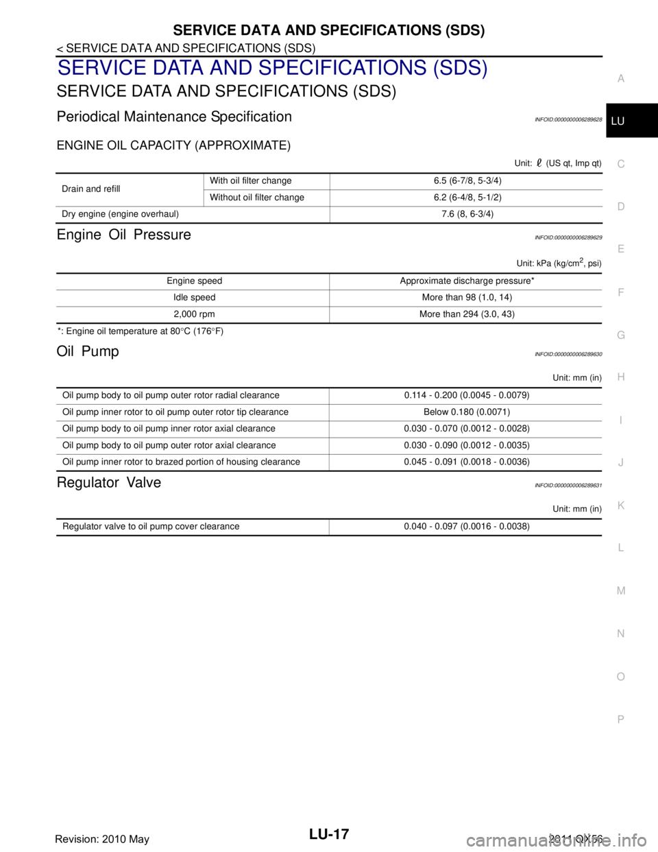
Periodical Maintenance SpecificationINFOID:0000000006289628
ENGINE OIL CAPACITY (APPROXIMATE)
Unit: (US qt, Imp qt)
Engine Oil PressureINFOID:0000000006289629
Unit: kPa (kg/cm2, psi)
*: Engine oil temperature at 80
°C (176 °F)
Oil PumpINFOID:0000000006289630
Unit: mm (in)
Regulator ValveINFOID:0000000006289631
Unit: mm (in)
Drain and refill With oil filter change 6.5 (6-7/8, 5-3/4)
Without oil filter change 6.2 (6-4/8, 5-1/2)
Dry engine (engine overhaul) 7.6 (8, 6-3/4)
Engine speed Approximate discharge pressure* Idle speed More than 98 (1.0, 14)2,000 rpm More than 294 (3.0, 43)
Oil pump body to oil pump outer rotor radial clearance 0.114 - 0.200 (0.0045 - 0.0079)
Oil pump inner rotor to oil pump outer rotor tip clearance Below 0.180 (0.0071)
Oil pump body to oil pump inner rotor axial clearance 0.030 - 0.070 (0.0012 - 0.0028)
Oil pump body to oil pump outer rotor axial clearance 0.030 - 0.090 (0.0012 - 0.0035)
Oil pump inner rotor to brazed portion of housing clearance 0.045 - 0.091 (0.0018 - 0.0036)
Regulator valve to oil pump cover clearance 0.040 - 0.097 (0.0016 - 0.0038)
Revision: 2010 May2011 QX56
Page 3688 of 5598
MA-18
< PERIODIC MAINTENANCE >
ENGINE MAINTENANCE
3. Warm up the engine and check area around drain plug and oil filter for engine oil leakage.
4. Stop the engine and wait for 10 minutes.
5. Check the engine oil level. Refer to LU-7, "
Inspection".
OIL FILTER
OIL FILTER : Removal and InstallationINFOID:0000000006394843
REMOVAL
1. Remove front under cover.
2. Drain engine oil. Refer to MA-17, "
ENGINE OIL : Draining".
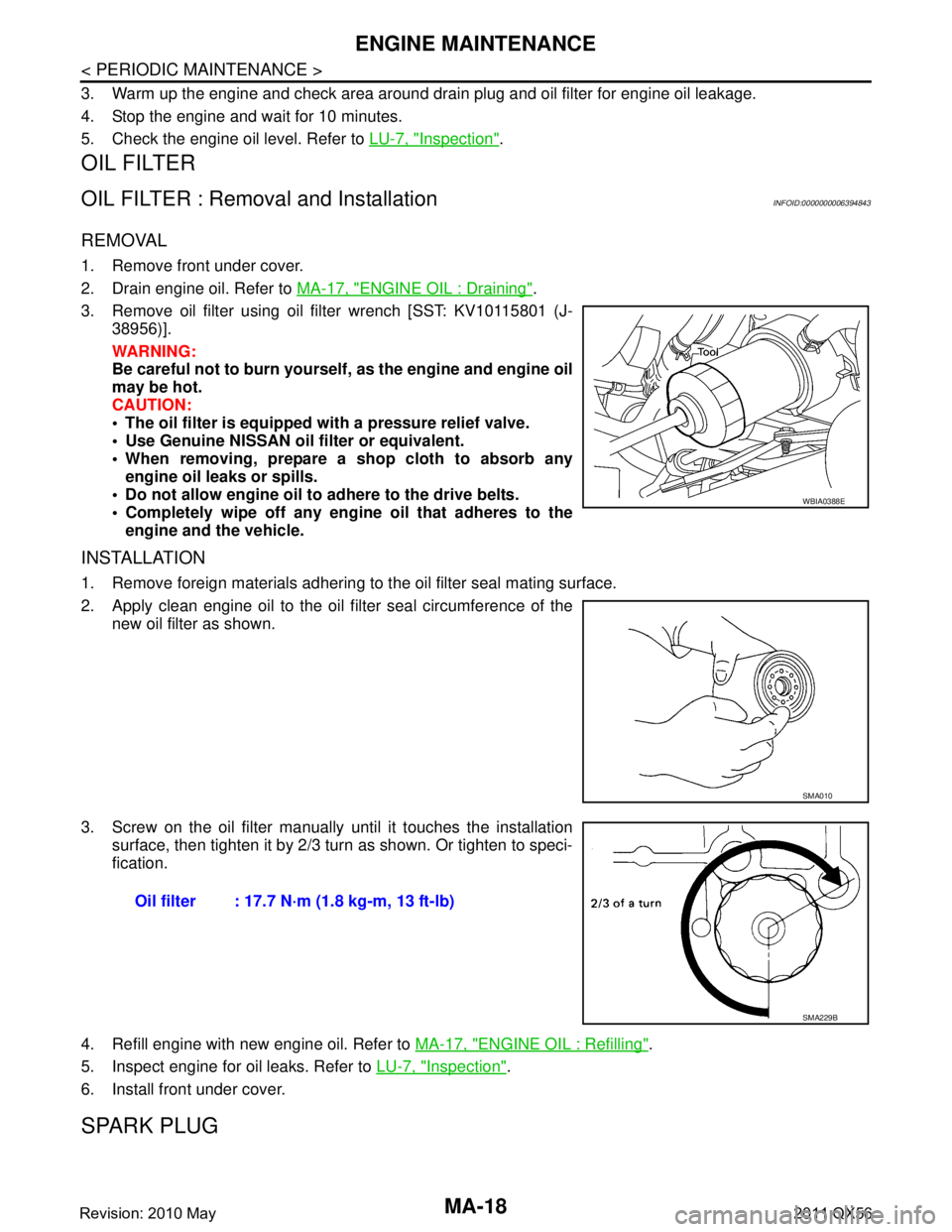
3. Remove oil filter using oil filter wrench [SST: KV10115801 (J- 38956)].
WARNING:
Be careful not to burn yourself, as the engine and engine oil
may be hot.
CAUTION:
The oil filter is equipped with a pressure relief valve.
Use Genuine NISSAN oil filter or equivalent.
When removing, prepare a sh op cloth to absorb any
engine oil leaks or spills.
Do not allow engine oil to adhere to the drive belts.
Completely wipe off any engi ne oil that adheres to the
engine and the vehicle.
INSTALLATION
1. Remove foreign materials adhering to the oil filter seal mating surface.
2. Apply clean engine oil to the oil f ilter seal circumference of the
new oil filter as shown.
3. Screw on the oil filter manually until it touches the installation
surface, then tighten it by 2/3 turn as shown. Or tighten to speci-
fication.
4. Refill engine with new engine oil. Refer to MA-17, "
ENGINE OIL : Refilling".
5. Inspect engine for oil leaks. Refer to LU-7, "
Inspection".
6. Install front under cover.
SPARK PLUG
WBIA0388E
SMA010
Oil filter : 17.7 N·m (1.8 kg-m, 13 ft-lb)
SMA229B
Revision: 2010 May2011 QX56
Page 3689 of 5598
ENGINE MAINTENANCEMA-19
< PERIODIC MAINTENANCE >
C
DE
F
G H
I
J
K L
M B
MA
N
O A
SPARK PLUG : Removal and InstallationINFOID:0000000006394839
REMOVAL
1. Remove engine cover. Refer to
EM-25, "Exploded View".
2. Remove ignition coil. Refer to EM-29, "
Exploded View".
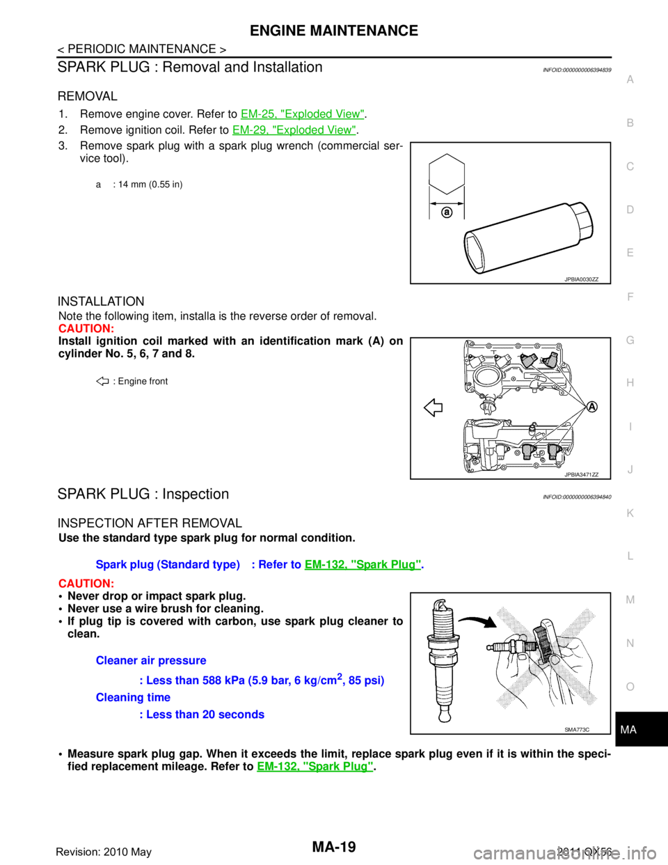
3. Remove spark plug with a spark plug wrench (commercial ser- vice tool).
INSTALLATION
Note the following item, installa is the reverse order of removal.
CAUTION:
Install ignition coil marked wi th an identification mark (A) on
cylinder No. 5, 6, 7 and 8.
SPARK PLUG : InspectionINFOID:0000000006394840
INSPECTION AFTER REMOVAL
Use the standard type spark plug for normal condition.
CAUTION:
Never drop or impact spark plug.
Never use a wire brush for cleaning.
If plug tip is covered with carbon, use spark plug cleaner to
clean.
Measure spark plug gap. When it exceeds the limit, replace spark plug even if it is within the speci-
fied replacement mileage. Refer to EM-132, "
Spark Plug".
a : 14 mm (0.55 in)
JPBIA0030ZZ
: Engine front
JPBIA3471ZZ
Spark plug (Standard type) : Refer to EM-132, "Spark Plug".
Cleaner air pressure : Less than 588 kPa (5.9 bar, 6 kg/cm
2, 85 psi)
Cleaning time
: Less than 20 seconds
SMA773C
Revision: 2010 May2011 QX56
Page 3698 of 5598
MA-28
< PERIODIC MAINTENANCE >
CHASSIS MAINTENANCE
BRAKE FLUID LEVEL AND LEAKS : Inspection
INFOID:0000000006220939
Check that the fluid level in the sub tank is within the specified range (MAX – MIN lines).
CAUTION:
Turn OFF the ignition switch an d depress the brake pedal 20 times or more to check brake fluid level.
NOTE:
Since brake fluid is in the accumulator in pressurized condition, the reservoir tank brake fluid level should be
lower than the MAX line.
Visually check for any brake fluid leakage around the reservoir tank.
Check the brake system for any leakage if the fl uid level is extremely low (lower than MIN).
Check the brake system for fluid leakage if the warn ing lamp remains illuminated even after the parking
brake is released.
Check the sub tank for the mixing of foreign ma tter (e.g. dust) and oils other than brake fluid.
BRAKE LINES AND CABLES
BRAKE LINES AND CABLES : InspectionINFOID:0000000006220940
1. Check brake line (tubes and hoses) for cracks, deterioration or other damage. Replace any damaged
parts.
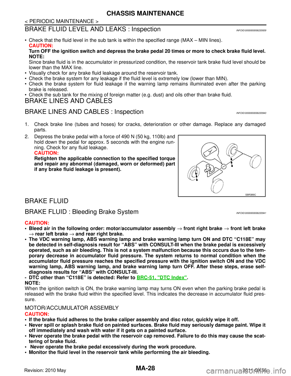
2. Depress the brake pedal with a force of 490 N (50 kg, 110lb) and hold down the pedal for approx. 5 seconds with the engine run-
ning. Check for any fluid leakage.
CAUTION:
Retighten the applicable conn ection to the specified torque
and repair any abnormal (damag ed, worn or deformed) part
if any brake fluid leakage is present).
BRAKE FLUID
BRAKE FLUID : Bleeding Brake SystemINFOID:0000000006220941
CAUTION:
Bleed air in the following order: motor/accumulator assembly → front right brake → front left brake
→ rear left brake → and rear right brake.
The VDC warning lamp, ABS warning lamp and br ake warning lamp turn ON and DTC “C118E” may
be detected in self-diagnosis r esult for “ABS” with CONSULT-II I when the brake pedal is excessively
operated, such as air bleeding. Thi s is not a system malfunction becau se this occurs due to the tem-
porary decrease in accumulator fl uid pressure. The system returns to normal condition when the
accumulator fluid pressure reaches the specified pressu re with the ignition switch ON and the VDC
warning lamp, ABS warning lamp, and brake warnin g lamp turn OFF. After these steps, erase self-
diagnosis results for “ABS” with CONSULT-III.
- DTC other than “C118E” is detected: Refer to BRC-51, "
DTC Index".
NOTE:
When the ignition switch is ON, the brake warning la mp may turns ON even when the parking brake pedal is
released with the brake fluid within the specified level. This indicates the decrease in accumulator fluid pres-
sure.
MOTOR/ACCUMULATOR ASSEMBLY
CAUTION:
If the brake fluid adheres to the brake caliper assembly and disc rotor, quickly wipe it off.
Never spill or splash brake fluid on painted surfaces. Brake fluid may seriously damage paint. Wipe it
off immediately and wash with wate r if it gets on a painted surface.
Never operate the brake pedal with the reservoir cap removed. Failure to do this may cause the scat-
tering of brake fluid.
Never operate the brake pedal excessively during the work procedure.
Monitor the fluid level in the reservoir tank while performing the air bleeding.
SBR389C
Revision: 2010 May2011 QX56
Page 3699 of 5598
CHASSIS MAINTENANCEMA-29
< PERIODIC MAINTENANCE >
C
DE
F
G H
I
J
K L
M B
MA
N
O A
Bleed air in the following
order: motor/accumulator assembly → front right brake → front left brake
→ rear left brake → and rear right brake.
1. Turn the ignition switch OFF.
2. Depress the brake pedal 20 times or more.
3. Check that there is no foreign material in t he reservoir tank, and refill with new brake fluid.
CAUTION:
Never reuse drained brake fluid.
Never allow oils other than brake fl uid to enter the reservoir tank.
4. Turn the ignition switch ON. NOTE:
The motor is activated and automatically stops.
5. Turn the ignition switch OFF.
6. Depress the brake pedal 20 times or more. NOTE:
The pressure loss in the accumulator results in a large brake pedal stroke. In addition to this, the brake
pedal depression becomes lighter in initial stage.
7. Repeat steps 4 to 6 for 5 times.
8. Turn the ignition switch ON to check that the time between motor activation and automatic stop is less
than 18 seconds. If the time is 18 seconds or more, repeat from Step 4 to 8.
FRONT BRAKE
CAUTION:
If the brake fluid adheres to the brake caliper assembly and disc rotor, quickly wipe it off.
Never spill or splash brake fluid on painted surfaces. Brake fluid may seriously damage paint. Wipe it
off immediately and wash with wate r if it gets on a painted surface.
Never operate the brake pedal with the reservoir cap removed. Failure to do this may cause the scat-
tering of brake fluid.
Never operate the brake pedal excessively during the work procedure.
Monitor the fluid level in the reservoir tank while performing the air bleeding.
Bleed air in the following order: motor/accumulator assembly → front right brake → front left brake
→ rear left brake → and rear right brake.
1. Turn the ignition switch OFF.
2. Depress the brake pedal 20 times or more. NOTE:
The pressure loss in the accumulator results in a large brake pedal stroke. In addition to this, the brake
pedal depression becomes lighter in initial stage.
3. Check that there is no foreign material in t he reservoir tank, and refill with new brake fluid.
CAUTION:
Never reuse drained brake fluid.
Never allow oils other than brake fl uid to enter the reservoir tank.
4. Turn the ignition switch ON.
5. Connect a vinyl tube to the bleed valve.
6. Depress the brake pedal and loosen the bleeder valve.
7. Repeat steps 1 to 6 until all of the air is out of the brake line and tighten the air bleeder to the specified
torque with the brake pedal depressed. Refer to BR-36, "
BRAKE CALIPER ASSEMBLY : Exploded View".
8. Check that no drag feel is present for the front disc brake. Refer to BR-39, "
BRAKE CALIPER ASSEMBLY
: Inspection".
9. Check each item of brake pedal. Adjust it if t he measurement value is not the standard. Refer to BR-7,
"Inspection and Adjustment".
REAR BRAKE
CAUTION:
If the brake fluid adheres to the brake caliper assembly and disc rotor, quickly wipe it off.
Never spill or splash brake fluid on painted surfaces. Brake fluid may seriously damage paint. Wipe it
off immediately and wash with wate r if it gets on a painted surface.
Never operate the brake pedal with the reservoir cap removed. Failure to do this may cause the scat-
tering of brake fluid.
Revision: 2010 May2011 QX56
Page 3700 of 5598
MA-30
< PERIODIC MAINTENANCE >
CHASSIS MAINTENANCE
Never operate the brake pedal excessively during the work procedure.
Monitor the fluid level in the reservoir tank while performing the air bleeding.
Bleed air in the following order: motor/accumulator assembly → front right brake → front left brake
→ rear left brake → and rear right brake.
1. Turn the ignition switch OFF.
2. Depress the brake pedal 20 times or more. NOTE:
The pressure loss in the accumulator results in a large brake pedal stroke. In addition to this, the brake
pedal depression becomes lighter in initial stage.
3. Check that there is no foreign material in the reservoir tank, and refill with new brake fluid. CAUTION:
Never reuse drained brake fluid.
Never allow oils other than brake fluid to enter the reservoir tank.
4. Turn the ignition switch ON.
5. Connect a vinyl tube to the bleed valve.
6. Depress the brake pedal and loosen the bleeder valve.
7. Depress and hold the brake pedal depression to dischar ge 100 cc of brake fluid before tightening the air
bleeder to the specified torque. Refer to BR-42, "
BRAKE CALIPER ASSEMBLY : Exploded View".
NOTE:
Since brake fluid is conveyed by the motor, the brake pedal is not necessarily depressed.
8. Release the brake pedal.
9. Repeat steps 1 to 8 until all of the air is out of the brake line and tighten the air bleeder to the specified
torque with the brake pedal depressed. Refer to BR-42, "
BRAKE CALIPER ASSEMBLY : Exploded View".
10. Check that no drag feel is present for the rear disc brake. Refer to BR-45, "
BRAKE CALIPER ASSEMBLY
: Inspection".
11. Check each item of brake pedal. Adjust it if t he measurement value is not the standard. Refer to BR-7,
"Inspection and Adjustment".
BRAKE FLUID LEVEL ADJUSTMENT AFTER AIR BLEEDING
1. Turn the ignition switch OFF.
2. Depress the brake pedal 20 times or more.
NOTE:
The pressure loss in the accumulator results in a large brake pedal stroke. In addition to this, the brake
pedal depression becomes lighter in initial stage.
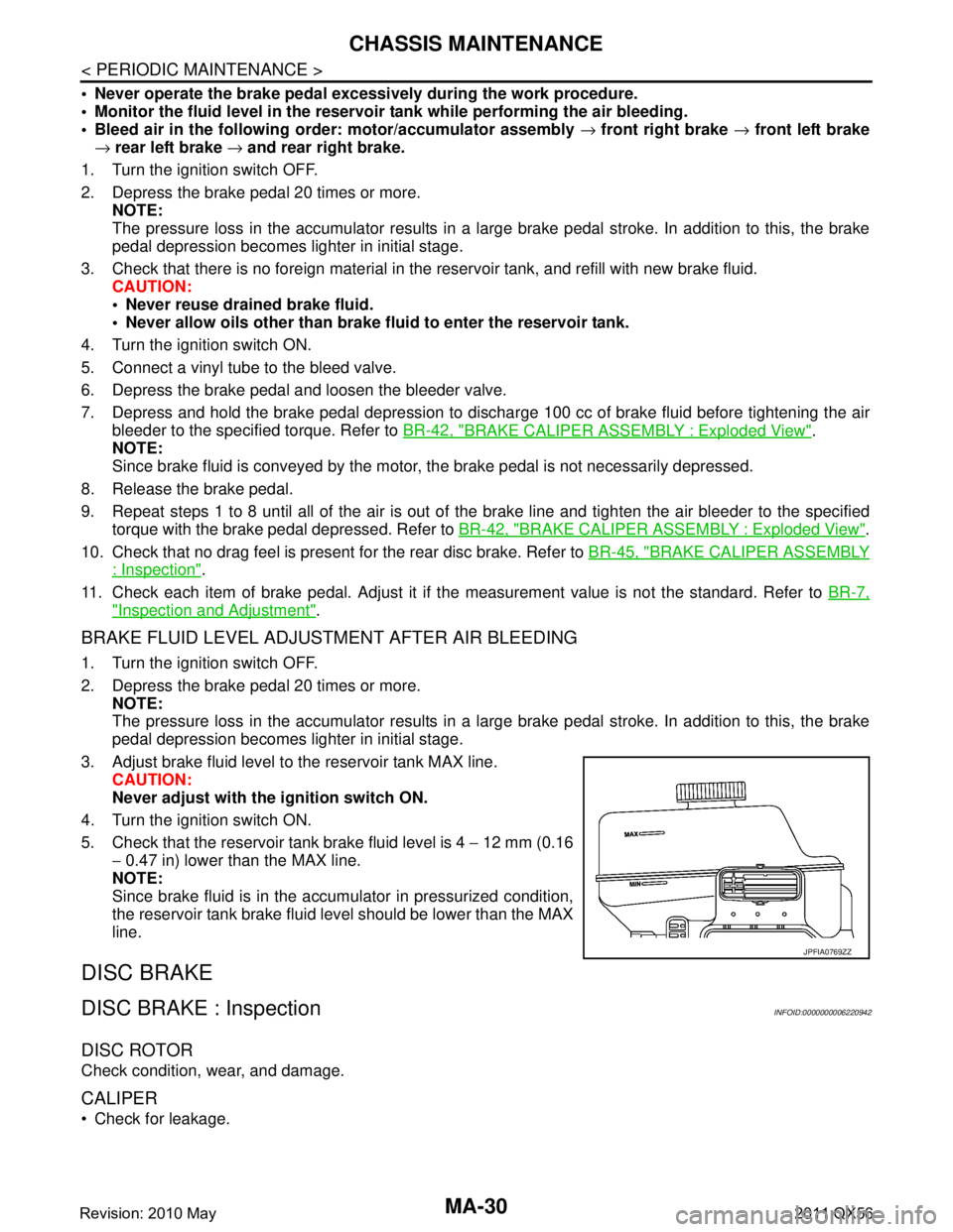
3. Adjust brake fluid level to the reservoir tank MAX line. CAUTION:
Never adjust with the ignition switch ON.
4. Turn the ignition switch ON.
5. Check that the reservoir tank brake fluid level is 4 − 12 mm (0.16
− 0.47 in) lower than the MAX line.
NOTE:
Since brake fluid is in the accumulator in pressurized condition,
the reservoir tank brake fluid level should be lower than the MAX
line.
DISC BRAKE
DISC BRAKE : InspectionINFOID:0000000006220942
DISC ROTOR
Check condition, wear, and damage.
CALIPER
Check for leakage.
JPFIA0769ZZ
Revision: 2010 May2011 QX56