2011 INFINITI QX56 low oil pressure
[x] Cancel search: low oil pressurePage 2653 of 5598

CYLINDER HEADEM-91
< REMOVAL AND INSTALLATION >
C
DE
F
G H
I
J
K L
M A
EM
NP
O
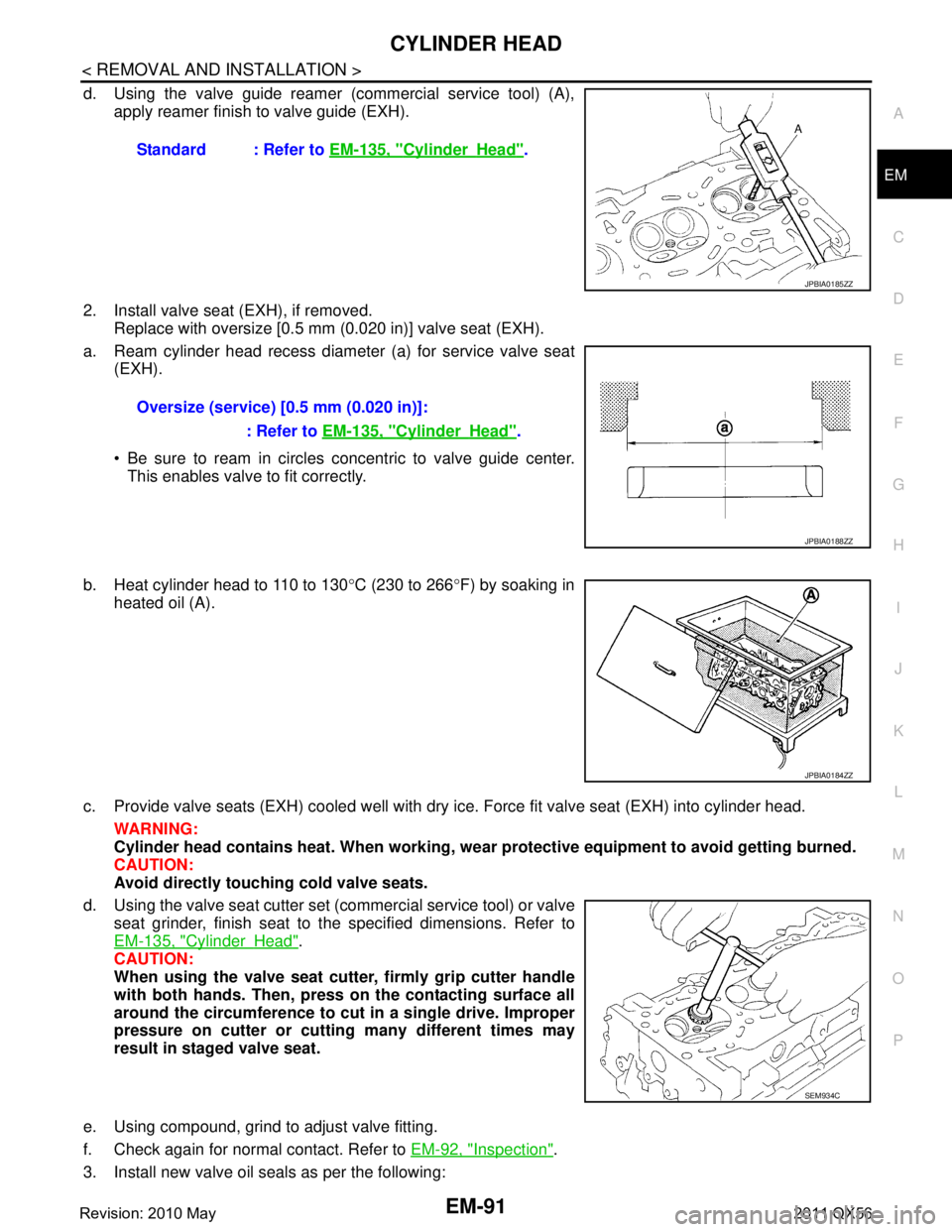
d. Using the valve guide reamer (commercial service tool) (A),
apply reamer finish to valve guide (EXH).
2. Install valve seat (EXH), if removed. Replace with oversize [0.5 mm (0.020 in)] valve seat (EXH).
a. Ream cylinder head recess diameter (a) for service valve seat (EXH).
Be sure to ream in circles concentric to valve guide center.
This enables valve to fit correctly.
b. Heat cylinder head to 110 to 130 °C (230 to 266 °F) by soaking in
heated oil (A).
c. Provide valve seats (EXH) cooled well with dry ice. Force fit valve seat (EXH) into cylinder head. WARNING:
Cylinder head contains heat. When working, w ear protective equipment to avoid getting burned.
CAUTION:
Avoid directly touching cold valve seats.
d. Using the valve seat cutter set (commercial service tool) or valve seat grinder, finish seat to the specified dimensions. Refer to
EM-135, "
CylinderHead".
CAUTION:
When using the valve seat cutt er, firmly grip cutter handle
with both hands. Then, press on the contacting surface all
around the circumference to cu t in a single drive. Improper
pressure on cutter or cutting many different times may
result in staged valve seat.
e. Using compound, grind to adjust valve fitting.
f. Check again for normal contact. Refer to EM-92, "
Inspection".
3. Install new valve oil seals as per the following: Standard : Refer to
EM-135, "
CylinderHead".
JPBIA0185ZZ
Oversize (service) [0.5 mm (0.020 in)]:
: Refer to EM-135, "
CylinderHead".
JPBIA0188ZZ
JPBIA0184ZZ
SEM934C
Revision: 2010 May2011 QX56
Page 2656 of 5598

EM-94
< REMOVAL AND INSTALLATION >
CYLINDER HEAD
Check if the contact area band is continuous all around the circum-ference.
- If not, grind to adjust valve fitting and check again. If the contacting surface still has “NG” conditions even after the re-check, replace
valve seat (EXH). Refer to EM-86, "
Exploded View". (Exhaust
side)
- If not, replace VVEL ladder assembly & cylinder head assembly. Refer to EM-86, "
Exploded View". (Intake side)
NOTE:
Since the valve seat (INT) cannot be replaced by t he piece, VVEL ladder assembly & cylinder head assem-
bly replacement are required.
Valve Spring (with valve spring seat) Squareness
Set a try square (A) along the side of valve spring (with valve
spring seat) and rotate spring. Measure the maximum clearance
between the top of spring and try square.
If it exceeds the limit.
- Replace valve spring (with valve spring seat) (EXH). Refer to EM-
86, "Exploded View". (Exhaust side)
- Replace VVEL ladder assembly & cylinder head assembly. Refer
to EM-86, "
Exploded View". (Intake side)
NOTE:
Since the valve spring (with valve spring seat) (INT) c annot be replaced by the piece, VVEL ladder assembly
& cylinder head assembly replacement are required.
Valve Spring Dimensions and Valve Spring Pressure Load
Check the valve spring (with valve spring seat) pressure at speci- fied spring height.
If the installation load or load with valve open is out of the stan- dard.
- Replace valve spring (with valve spring seat) (EXH). Refer to EM-
86, "Exploded View". (Exhaust side)
- Replace VVEL ladder assembly & cylinder head assembly. Refer to EM-86, "
Exploded View". (Intake side)
NOTE:
Since the valve spring (with valve spring seat) (INT) c annot be replaced by the piece, VVEL ladder assembly
& cylinder head assembly replacement are required.
INSPECTION AFTER ASSEMBLY
Inspection for Leakage
The following are procedures for checking fluid leakage, lubricant leakage.
Before starting engine, check oil/fluid levels includi ng engine coolant and engine oil. If any are less than the
required quantity, fill them to the specified level. Refer to MA-10, "
Fluids and Lubricants".
Follow the procedure below to check for fuel leakage.
- Turn ignition switch to the “ON” position (with engi ne stopped). With fuel pressure applied to fuel piping,
check for fuel leakage at connection points.
- Start engine. With engine speed increased, che ck again for fuel leakage at connection points.
Run engine to check for unusual noise and vibration. NOTE:
A: OK
B: NG
JPBIA0187ZZ
B : Contact
Limit : Refer to EM-135, "CylinderHead".
JPBIA0189ZZ
Standard
: Refer to EM-135, "
CylinderHead".
SEM113
Revision: 2010 May2011 QX56
Page 2662 of 5598

EM-100
< UNIT REMOVAL AND INSTALLATION >
ENGINE ASSEMBLY
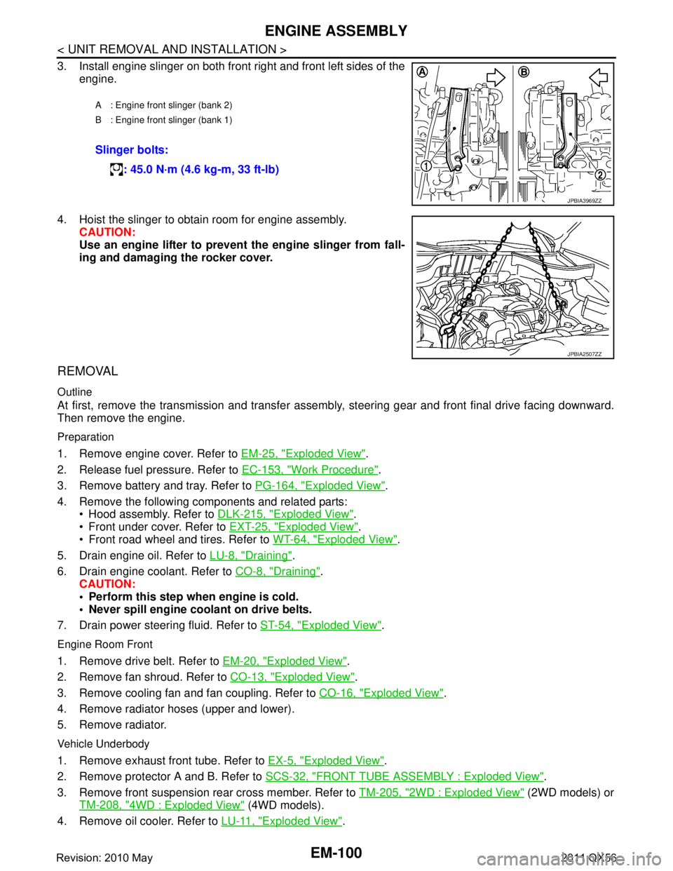
3. Install engine slinger on both front right and front left sides of theengine.
4. Hoist the slinger to obtain room for engine assembly. CAUTION:
Use an engine lifter to prevent the engine slinger from fall-
ing and damaging the rocker cover.
REMOVAL
Outline
At first, remove the transmission and transfer assemb ly, steering gear and front final drive facing downward.
Then remove the engine.
Preparation
1. Remove engine cover. Refer to EM-25, "Exploded View".
2. Release fuel pressure. Refer to EC-153, "
Work Procedure".
3. Remove battery and tray. Refer to PG-164, "
Exploded View".
4. Remove the following components and related parts: Hood assembly. Refer to DLK-215, "
Exploded View".
Front under cover. Refer to EXT-25, "
Exploded View".
Front road wheel and tires. Refer to WT-64, "
Exploded View".
5. Drain engine oil. Refer to LU-8, "
Draining".
6. Drain engine coolant. Refer to CO-8, "
Draining".
CAUTION:
Perform this step when engine is cold.
Never spill engine coolant on drive belts.
7. Drain power steering fluid. Refer to ST-54, "
Exploded View".
Engine Room Front
1. Remove drive belt. Refer to EM-20, "Exploded View".
2. Remove fan shroud. Refer to CO-13, "
Exploded View".
3. Remove cooling fan and fan coupling. Refer to CO-16, "
Exploded View".
4. Remove radiator hoses (upper and lower).
5. Remove radiator.
Vehicle Underbody
1. Remove exhaust front tube. Refer to EX-5, "Exploded View".
2. Remove protector A and B. Refer to SCS-32, "
FRONT TUBE ASSEMBLY : Exploded View".
3. Remove front suspension rear cross member. Refer to TM-205, "
2WD : Exploded View" (2WD models) or
TM-208, "
4WD : Exploded View" (4WD models).
4. Remove oil cooler. Refer to LU-11, "
Exploded View".
A : Engine front slinger (bank 2)
B : Engine front slinger (bank 1)
Slinger bolts:
: 45.0 N·m (4.6 kg-m, 33 ft-lb)
JPBIA3969ZZ
JPBIA2507ZZ
Revision: 2010 May2011 QX56
Page 2664 of 5598

EM-102
< UNIT REMOVAL AND INSTALLATION >
ENGINE ASSEMBLY
INSTALLATION
Install in the reverse order of removal.
CAUTION:
When replacing an engine or transmission you must make sure the dowels are installed correctly
during re-assembly.Improper alignment caused by mi ssing dowels may cause vibration, oil leaks or
breakage of drivetrain components.
InspectionINFOID:0000000006289578
INSPECTION AFTER INSTALLATION
Inspection for Leakage
The following are procedures for checking fluid leakage, lubricant leakage. Before starting engine, check oil/fluid levels includi ng engine coolant and engine oil. If any are less than the
required quantity, fill them to the specified level. Refer to MA-10, "
Fluids and Lubricants".
Follow the procedure below to check for fuel leakage.
- Turn ignition switch to the “ON” position (with engi ne stopped). With fuel pressure applied to fuel piping,
check for fuel leakage at connection points.
- Start engine. With engine speed increased, che ck again for fuel leakage at connection points.
Run engine to check for unusual noise and vibration. NOTE:
If hydraulic pressure inside chain tensioner drops af ter removal/installation, slack in guide may generate a
pounding noise during and just after the engine start. However, this does not indicate a malfunction. The
noise will stop after hydraulic pressure rises.
Warm up engine thoroughly to check that there is no leak age of fuel, or any oil/fluids including engine oil and
engine coolant.
Bleed air from lines and hoses of applic able lines, such as in cooling system.
After cooling down engine, again check oil/fluid levels including engine oil and engine coolant. Refill them to
the specified level, if necessary.
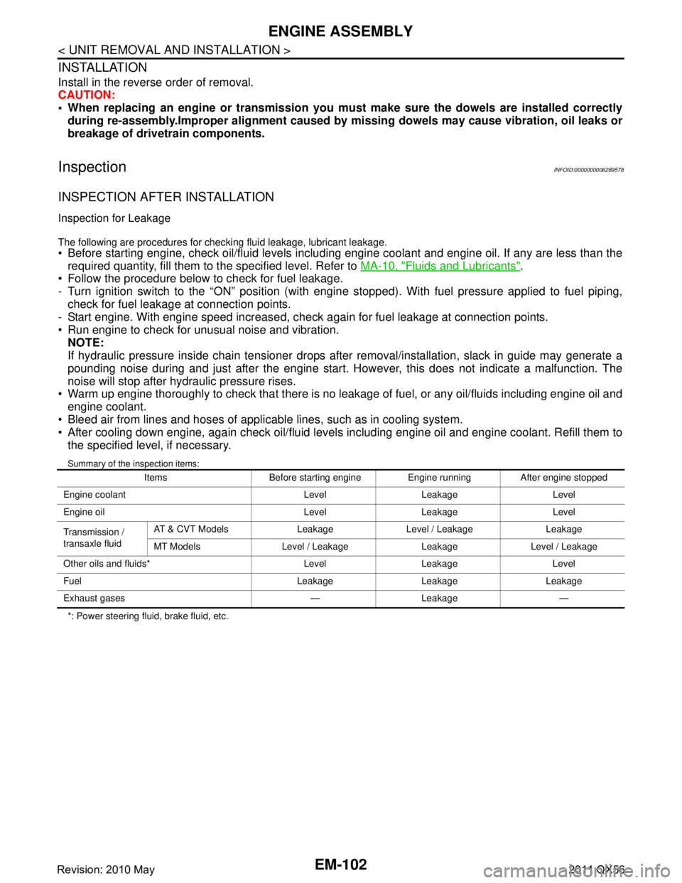
Summary of the inspection items:
*: Power steering fluid, brake fluid, etc. Items Before starting engine Engine running After engine stopped
Engine coolant Level Leakage Level
Engine oil Level Leakage Level
Transmission /
transaxle fluid AT & CVT Models Leakage Level / Leakage Leakage
MT Models Level / Leakage Leakage Level / Leakage
Other oils and fluids* Level Leakage Level
Fuel Leakage Leakage Leakage
Exhaust gases — Leakage —
Revision: 2010 May2011 QX56
Page 2737 of 5598
![INFINITI QX56 2011 Factory Service Manual
DIAGNOSIS SYSTEM (IPDM E/R)EXL-27
< SYSTEM DESCRIPTION > [XENON TYPE]
C
D
E
F
G H
I
J
K
M A
B
EXL
N
O P
DIAGNOSIS SYSTEM (IPDM E/R)
Diagnosis DescriptionINFOID:0000000006368066
AUTO ACTIVE TEST
Descr INFINITI QX56 2011 Factory Service Manual
DIAGNOSIS SYSTEM (IPDM E/R)EXL-27
< SYSTEM DESCRIPTION > [XENON TYPE]
C
D
E
F
G H
I
J
K
M A
B
EXL
N
O P
DIAGNOSIS SYSTEM (IPDM E/R)
Diagnosis DescriptionINFOID:0000000006368066
AUTO ACTIVE TEST
Descr](/manual-img/42/57033/w960_57033-2736.png)
DIAGNOSIS SYSTEM (IPDM E/R)EXL-27
< SYSTEM DESCRIPTION > [XENON TYPE]
C
D
E
F
G H
I
J
K
M A
B
EXL
N
O P
DIAGNOSIS SYSTEM (IPDM E/R)
Diagnosis DescriptionINFOID:0000000006368066
AUTO ACTIVE TEST
Description
In auto active test, the IPDM E/R sends a drive signal to the following systems to check their operation.
Oil pressure warning lamp
Rear window defogger
Front wiper (LO, HI)
Parking lamp
License plate lamp
Tail lamp
Side marker lamp
Front fog lamp
Headlamp (LO, HI)
A/C compressor (magnet clutch)
Operation Procedure
CAUTION:
Never perform auto active test in the following conditions.
Engine is running.
CONSULT-III is connected.
1. Close the hood and lift the wiper arms from the windshield. (Prevent windshield damage due to wiper
operation)
NOTE:
When auto active test is performed with hood opened, sprinkle water on windshield beforehand.
2. Turn the ignition switch OFF.
3. Turn the ignition switch ON, and within 20 seconds, pr ess the driver door switch 10 times. Then turn the
ignition switch OFF.
CAUTION:
Close passenger door.
4. Turn the ignition switch ON within 10 seconds. Af ter that the horn sounds once and the auto active test
starts.
CAUTION:
Engine starts when ignition switch is turned ON while brake pedal is depressed.
5. The oil pressure warning lamp starts blinking when the auto active test starts.
6. After a series of the following operations is repeated 3 times, auto active test is completed.
NOTE:
When auto active test has to be cancelled halfw ay through test, turn the ignition switch OFF.
When auto active test is not activated, door swit ch may be the cause. Check door switch. Refer to DLK-117,
"ComponentFunctionCheck".
Inspection in Auto Active Test
When auto active test is actuated, the following operation sequence is repeated 3 times.
Operation
sequence Inspection location Operation
1 Oil pressure warning lamp Blinks continuously during operation of auto active test
2 Rear window defogger 10 seconds
3 Front wiper LO for 5 seconds → HI for 5 seconds
4 Parking lamp
License plate lamp
Tail lamp
Side marker lamp
Front fog lamp 10 seconds
Revision: 2010 May2011 QX56
Page 2739 of 5598
![INFINITI QX56 2011 Factory Service Manual
DIAGNOSIS SYSTEM (IPDM E/R)EXL-29
< SYSTEM DESCRIPTION > [XENON TYPE]
C
D
E
F
G H
I
J
K
M A
B
EXL
N
O P
CONSULT-III Function (IPDM E/R)INFOID:0000000006368067
APPLICATION ITEM
CONSULT-III performs th INFINITI QX56 2011 Factory Service Manual
DIAGNOSIS SYSTEM (IPDM E/R)EXL-29
< SYSTEM DESCRIPTION > [XENON TYPE]
C
D
E
F
G H
I
J
K
M A
B
EXL
N
O P
CONSULT-III Function (IPDM E/R)INFOID:0000000006368067
APPLICATION ITEM
CONSULT-III performs th](/manual-img/42/57033/w960_57033-2738.png)
DIAGNOSIS SYSTEM (IPDM E/R)EXL-29
< SYSTEM DESCRIPTION > [XENON TYPE]
C
D
E
F
G H
I
J
K
M A
B
EXL
N
O P
CONSULT-III Function (IPDM E/R)INFOID:0000000006368067
APPLICATION ITEM
CONSULT-III performs the following functi ons via CAN communication with IPDM E/R.
SELF DIAGNOSTIC RESULT
Refer to PCS-22, "DTCIndex".
DATA MONITOR
Monitor item
Oil pressure warning lamp does not operate Perform auto active test.
Does the oil pressure warning
lamp blink?YES
Harness or connector be-
tween IPDM E/R and oil
pressure switch
Oil pressure switch
IPDM E/R
NO CAN communication signal
between IPDM E/R and
BCM
CAN communication signal
between BCM and combi-
nation meter
Combination meter
Symptom Inspection contents Possible cause
Diagnosis mode Description
Ecu Identification Allows confirmation of IPDM E/R part number.
Self Diagnostic Result Displays the diagnosis results judged by IPDM E/R.
Data Monitor Displays the real-time input/output data from IPDM E/R input/output data.
Active Test IPDM E/R can provide a drive signal to electronic components to check their operations.
CAN Diag Support Monitor The results of transmit/receive diagnosis of CAN communication can be read.
Monitor Item [Unit] MAIN SIG-
NALS Description
RAD FAN REQ
[1/2/3/4] ×Displays the value of the cooling fan speed request signal received from ECM via
CAN communication.
AC COMP REQ
[Off/On] ×Displays the status of the A/C compressor request signal received from ECM via
CAN communication.
TAIL&CLR REQ
[Off/On] ×
Displays the status of the position light request signal received from BCM via CAN
communication.
HL LO REQ
[Off/On] ×Displays the status of the low beam request signal received from BCM via CAN
communication.
HL HI REQ
[Off/On] ×Displays the status of the high beam request signal received from BCM via CAN
communication.
FR FOG REQ
[Off/On] ×Displays the status of the front fog light request signal received from BCM via
CAN communication.
FR WIP REQ
[Stop/1LOW/Low/Hi] ×
Displays the status of the front wiper request signal received from BCM via CAN
communication.
WIP AUTO STOP
[STOP P/ACT P] ×
Displays the status of the front wiper auto stop signal judged by IPDM E/R.
WIP PROT
[Off/BLOCK] ×
Displays the status of the front wiper fail-safe operation judged by IPDM E/R.
IGN RLY1 -REQ
[Off/On] Displays the status of the ignition switch ON signal received from BCM via CAN
communication.
IGN RLY
[Off/On] ×
Displays the status of the ignition relay judged by IPDM E/R.
Revision: 2010 May2011 QX56
Page 2831 of 5598
![INFINITI QX56 2011 Factory Service Manual
HEADLAMP AIMING ADJUSTMENTEXL-121
< PERIODIC MAINTENANCE > [XENON TYPE]
C
D
E
F
G H
I
J
K
M A
B
EXL
N
O P
PERIODIC MAINTENANCE
HEADLAMP AIMING ADJUSTMENT
descriptionINFOID:0000000006213990
preparatio INFINITI QX56 2011 Factory Service Manual
HEADLAMP AIMING ADJUSTMENTEXL-121
< PERIODIC MAINTENANCE > [XENON TYPE]
C
D
E
F
G H
I
J
K
M A
B
EXL
N
O P
PERIODIC MAINTENANCE
HEADLAMP AIMING ADJUSTMENT
descriptionINFOID:0000000006213990
preparatio](/manual-img/42/57033/w960_57033-2830.png)
HEADLAMP AIMING ADJUSTMENTEXL-121
< PERIODIC MAINTENANCE > [XENON TYPE]
C
D
E
F
G H
I
J
K
M A
B
EXL
N
O P
PERIODIC MAINTENANCE
HEADLAMP AIMING ADJUSTMENT
descriptionINFOID:0000000006213990
preparation before adjusting
NOTE:
for details, refer to the regulations in your own country.
perform aiming if the vehicle front body has been repaired and/or the headlamp assembly has been
replaced.
before performing aiming adjustment, check the following. adjust the tire pressure to the specification.
fill with fuel, engine coolant and each oil.
maintain the unloaded vehicle condition. (remove luggage from the passenger compartment and the lug- gage room.)
NOTE:
do not remove the temporary tire, jack and on-vehicle tool.
wipe out dirt on the headlamp.
CAUTION:
never use organic solvent (thinner, gasoline etc.)
ride alone on the driver seat.
aiming adjustment screw
JMLIA1319ZZ
A. Headlamp RH HI /LO (UP/DOWN)
adjustment screw B. Headlamp LH HI/LO (UP/DOWN)
adjustment screw
: Vehicle center
Revision: 2010 May2011 QX56
Page 2833 of 5598
![INFINITI QX56 2011 Factory Service Manual
FRONT FOG LAMP AIMING ADJUSTMENTEXL-123
< PERIODIC MAINTENANCE > [XENON TYPE]
C
D
E
F
G H
I
J
K
M A
B
EXL
N
O P
FRONT FOG LAMP AI MING ADJUSTMENT
DescriptionINFOID:0000000006213992
PREPARATION BEFORE INFINITI QX56 2011 Factory Service Manual
FRONT FOG LAMP AIMING ADJUSTMENTEXL-123
< PERIODIC MAINTENANCE > [XENON TYPE]
C
D
E
F
G H
I
J
K
M A
B
EXL
N
O P
FRONT FOG LAMP AI MING ADJUSTMENT
DescriptionINFOID:0000000006213992
PREPARATION BEFORE](/manual-img/42/57033/w960_57033-2832.png)
FRONT FOG LAMP AIMING ADJUSTMENTEXL-123
< PERIODIC MAINTENANCE > [XENON TYPE]
C
D
E
F
G H
I
J
K
M A
B
EXL
N
O P
FRONT FOG LAMP AI MING ADJUSTMENT
DescriptionINFOID:0000000006213992
PREPARATION BEFORE ADJUSTING
NOTE:
For details, refer to the regulations in your own country.
Perform aiming if the vehicle front body has been repaired and/or the headlamp assembly has been
replaced.
Before performing aiming adjustm ent, check the following. Adjust the tire pressure to the specification.
Fill with fuel, engine coolant and each oil.
Maintain the unloaded vehicle condition. (Remove luggage from the passenger compartment and the trunk
room.)
NOTE:
Do not remove the temporary tire, jack and on-vehicle tool.
Wipe out dirt on the headlamp. CAUTION:
Never use organic solvent (thinner, gasoline etc.)
Ride alone on the driver seat.
AIMING ADJUSTMENT SCREW
Turn the aiming adjusting screw for adjustment.
For the position and direction of the adjusting screw, refer to the figure.
NOTE:
A screwdriver or hexagonal wrench [6 mm (0.24 in)] can be used
for adjustment.
Aiming Adjustment ProcedureINFOID:0000000006213993
1. Place the screen. NOTE:
Stop the vehicle facing the wall.
Place the board on a plain road vertically.
2. Face the vehicle with the screen. Maintain 10 m (32.8 ft) between the front fog lamp center and the
screen.
3. Start the engine. Turn the front fog lamp ON. NOTE:
Shut off the headlamp light with the board to pr event from illuminating the adjustment screen.
CAUTION:
Never cover the lens surface with a tape etc. The lens is made of resin.
4. Adjust the cutoff line height (A) with the aiming adjus tment screw so that the distance (X) between the hor-
izontal center line of front fog lamp (H) and (A) becomes 200 mm (7.87 in).
A: UP
B: DOWN
JPLIA0915ZZ
Revision: 2010 May2011 QX56