2011 FORD KUGA hub
[x] Cancel search: hubPage 64 of 2057

– that the speedometer, coolant temperaturegauge and tachometer (if equipped) register the
correct readings and operate correctly.
– that the switches and controls operate smoothly and positively, warning and indicator lamps
operate correctly and the direction indicator
control self cancels when the steering is
returned to the straight ahead position.
– that the heating and ventilation systems operate correctly and effectively.
– the brake operation and efficiency.
Brake Testing
WARNING: When brake testing, avoid
breathing the fumes from hot brakes, this
may contain asbestos dust which is
hazardous to health. Failure to follow this
instruction may result in personal injury.
For additional information, refer to: Health
and Safety Precautions (100-00 General
Information, Description and Operation).
CAUTIONS:
Avoid brake testing on busy roads where
it may cause inconvenience or danger to
other road users.
Brake testing which includes heavy brake
applications should not be carried out with
new brake pads/discs or linings/drums
until the components have bedded-in. New
brake friction components will not reach
full efficiency until the bedding-in process
is complete.
Test the brakes at several speeds within the normal
operating range using both light and heavy pedal
pressure. Note any tendency to snatch, pull or
drag, and any undue delay in application or
release.
Allow the vehicle to coast and note any tendency
to pull to one side, or evidence that the brakes are
binding.
After stopping the vehicle (not immediately after a
period of heavy braking), carefully check the brake
temperature. A brake disc or brake drum that feels
hot or is appreciably hotter than the others,
indicates that the brake is binding.
After completion of the test, check for: – oil, coolant, hydraulic, air and fuel leaks.
– abnormal temperature of any moving
components or assemblies, for example wheel
hubs, transmission and axle, which might
indicate over tightness or lack of lubrication.
G17375en2008.50 Kuga8/2011
100-00- 59
General Information
100-00- 59
DESCRIPTION AND OPERATION
TO MODEL INDEX
BACK TO CHAPTER INDEX
FORD KUGA 2011.0MY WORKSHOP REPAIR MANUAL
Page 82 of 2057

sometimes noticed in the steering wheel/column,
seats, front floor panel, front door trim panel or
front end sheet metal. It is a low frequency
vibration (around 9-15 cycles per second). It
may or may not be increased by applying the
brakes lightly. REFER to Idle
Boom/Shake/Vibration in the Driveline Noise
and Vibration Symptom Chart.
3. High Speed: A vibration is felt in the front floor panel or seats with no visible shake, but with
an accompanying sound or rumble, buzz, hum,
drone or booming noise. Coast with the clutch
pedal depressed (manual transmission) or shift
control selector lever in "N" (NEUTRAL)
(automatic transmission) and engine idling. If
vibration is still evident, it may be related to
wheels, tires, front brake discs, wheel hubs or
front wheel bearings. REFER to Shake and
Vibration While Driving in the Driveline Noise
and Vibration Symptom Chart.
4. Engine rpm Sensitive: A vibration is felt whenever the engine reaches a particular rpm.
It will disappear in neutral coasts. The vibration
can be duplicated by operating the engine at
the problem rpm while the vehicle is stationary.
It can be caused by any component, from the
accessory drive belt to the clutch or torque
converter which turns at engine speed when the
vehicle is stopped. REFER to Shake and
Vibration While Driving in the Driveline Noise
and Vibration Symptom Chart.
5. Noise and Vibration While Turning: Clicking, popping or grinding noises may be due to the
following:
• worn, damaged or incorrectly installed front wheel bearing.
• damaged powertrain/drivetrain mounts.
Road Conditions
An experienced technician will always establish a
route that will be used for all NVH diagnosis road
tests. The road selected should be reasonably
smooth, level and free of undulations (unless a
particular condition needs to be identified). A
smooth asphalt road that allows driving over a
range of speeds is best. Gravel or bumpy roads
are unsuitable because of the additional road noise
produced. Once the route is established and consistently used, the road noise variable is
eliminated from the test results.
NOTE:
Some concerns may be apparent only on
smooth asphalt roads.
If a customer complains of a noise or vibration on
a particular road and only on a particular road, the
source of the concern may be the road surface. If
possible, try to test the vehicle on the same type
of road.
Vehicle Preparation
Carry out a thorough visual inspection of the
vehicle before carrying out the road test. Note
anything which is unusual. Do not repair or adjust
any condition until the road test is carried out,
unless the vehicle is inoperative or the condition
could pose a hazard to the technician. After
verifying that the condition has been corrected,
make sure all components removed have been
installed.
Power Steering Conditions
Check for the noise in the following conditions to
verify the customer concern.
• Check for the noise in several temperature conditions.
• Is the noise from when the vehicle was new?
• Can the noise be repeated constantly or is it random?
• Check the condition of the vehicle age, mileage and service record.
• Interview the customer to find the operating condition in which the noise will occur. Test the
vehicle based on the detail(s) from the customer
interview.
• Follow the power steering operation noise condition tables below, to find which condition
the noise will occur.
Power Steering Operation Noise Check
Step 1: Check for NVH concerns from non-steering
components, which may sound like noises coming
from the steering system.
G37349en2008.50 Kuga8/2011
100-04- 4
Noise, Vibration and Harshness
100-04- 4
DIAGNOSIS AND TESTING
TO MODEL INDEX
BACK TO CHAPTER INDEX
FORD KUGA 2011.0MY WORKSHOP REPAIR MANUAL
Page 1165 of 2057
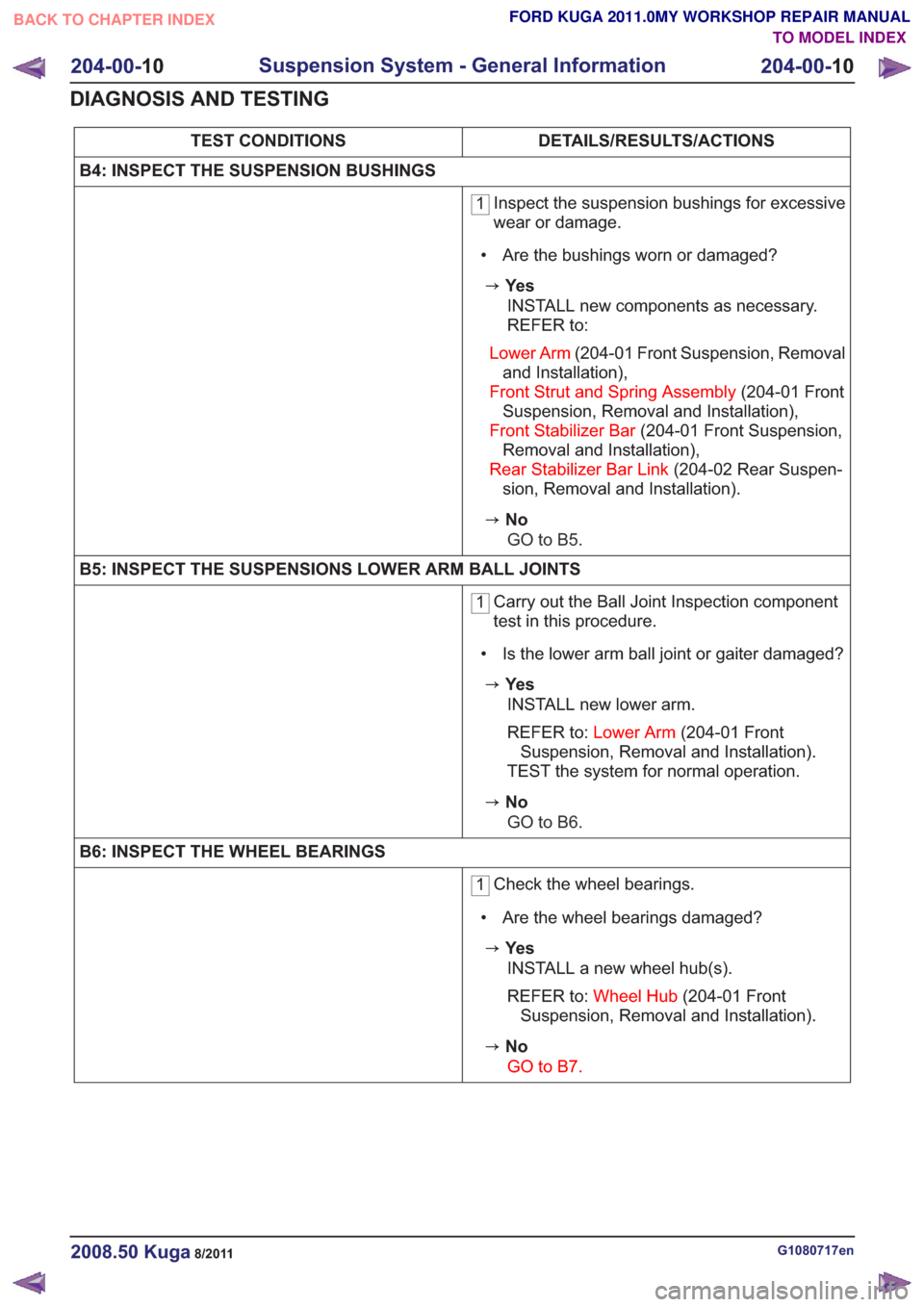
DETAILS/RESULTS/ACTIONS
TEST CONDITIONS
B4: INSPECT THE SUSPENSION BUSHINGS
1 Inspect the suspension bushings for excessive
wear or damage.
• Are the bushings worn or damaged?
zYe s INSTALL new components as necessary.
REFER to:
Lower Arm (204-01 Front Suspension, Removal
and Installation),
Front Strut and Spring Assembly (204-01 Front
Suspension, Removal and Installation),
Front Stabilizer Bar (204-01 Front Suspension,
Removal and Installation),
Rear Stabilizer Bar Link (204-02 Rear Suspen-
sion, Removal and Installation).
zNo
GO to B5.
B5: INSPECT THE SUSPENSIONS LOWER ARM BALL JOINTS
1 Carry out the Ball Joint Inspection component
test in this procedure.
• Is the lower arm ball joint or gaiter damaged?
zYe s INSTALL new lower arm.
REFER to: Lower Arm (204-01 Front
Suspension, Removal and Installation).
TEST the system for normal operation.
zNo
GO to B6.
B6: INSPECT THE WHEEL BEARINGS
1 Check the wheel bearings.
• Are the wheel bearings damaged?
zYe s INSTALL a new wheel hub(s).
REFER to: Wheel Hub (204-01 Front
Suspension, Removal and Installation).
zNo
GO to B7.
G1080717en2008.50 Kuga8/2011
204-00- 10
Suspension System - General Information
204-00- 10
DIAGNOSIS AND TESTING
TO MODEL INDEX
BACK TO CHAPTER INDEX
FORD KUGA 2011.0MY WORKSHOP REPAIR MANUAL
Page 1172 of 2057
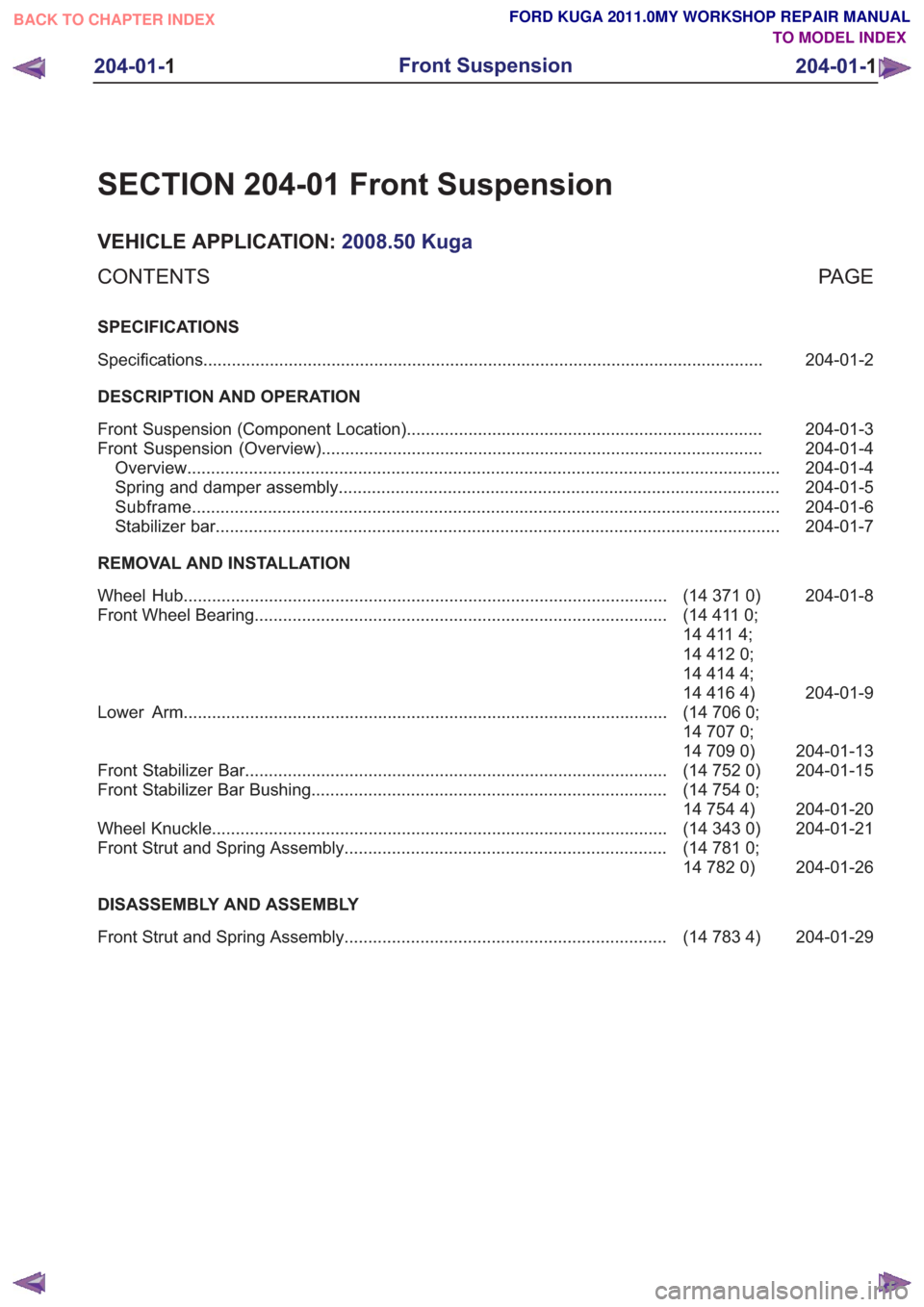
SECTION 204-01 Front Suspension
VEHICLE APPLICATION:2008.50 Kuga
PA G E
CONTENTS
SPECIFICATIONS
204-01-2
Specifications ........................................................................\
..............................................
DESCRIPTION AND OPERATION 204-01-3
Front Suspension (Component Location) ........................................................................\
...
204-01-4
Front Suspension (Overview) ........................................................................\
.....................
204-01-4
Overview ........................................................................\
.....................................................
204-01-5
Spring and damper assembly ........................................................................\
.....................
204-01-6
Subframe ........................................................................\
....................................................
204-01-7
Stabilizer bar ........................................................................\
...............................................
REMOVAL AND INSTALLATION 204-01-8
(14 371 0)
Wheel Hub ........................................................................\
..............................
204-01-9
(14 411 0;
14 411 4;
Front Wheel Bearing
........................................................................\
...............
14 412 0;
14 414 4;
14 416 4)
204-01-13
(14 706 0;
14 707 0;
14 709 0)
Lower Arm
........................................................................\
..............................
204-01-15
(14 752 0)
Front Stabilizer Bar ........................................................................\
.................
204-01-20
(14 754 0;
14 754 4)
Front Stabilizer Bar Bushing
........................................................................\
...
204-01-21
(14 343 0)
Wheel Knuckle ........................................................................\
........................
204-01-26
(14 781 0;
14 782 0)
Front Strut and Spring Assembly
....................................................................
DISASSEMBLY AND ASSEMBLY 204-01-29
(14 783 4)
Front Strut and Spring Assembly ....................................................................
204-01-1
Front Suspension
204-01- 1
.
TO MODEL INDEX
BACK TO CHAPTER INDEX
FORD KUGA 2011.0MY WORKSHOP REPAIR MANUAL
Page 1176 of 2057
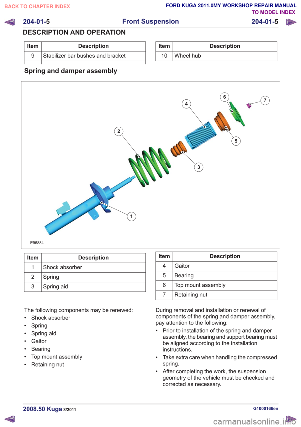
Description
Item
Stabilizer bar bushes and bracket
9Description
Item
10 Wheel hub
Spring and damper assembly
E96884
1
2
3
4
5
67
Description
Item
Shock absorber
1
Spring
2
Spring aid
3Description
Item
Gaitor
4
Bearing
5
Top mount assembly
6
Retaining nut
7
The following components may be renewed:
• Shock absorber
• Spring
• Spring aid
• Gaitor
• Bearing
• Top mount assembly
• Retaining nut During removal and installation or renewal of
components of the spring and damper assembly,
pay attention to the following:
• Prior to installation of the spring and damper
assembly, the bearing and support bearing must
be aligned according to the installation
instructions.
• Take extra care when handling the compressed spring.
• After completing the work, the suspension geometry of the vehicle must be checked and
corrected as necessary.
G1000166en2008.50 Kuga8/2011
204-01- 5
Front Suspension
204-01- 5
DESCRIPTION AND OPERATION
TO MODEL INDEX
BACK TO CHAPTER INDEX
FORD KUGA 2011.0MY WORKSHOP REPAIR MANUAL
Page 1179 of 2057
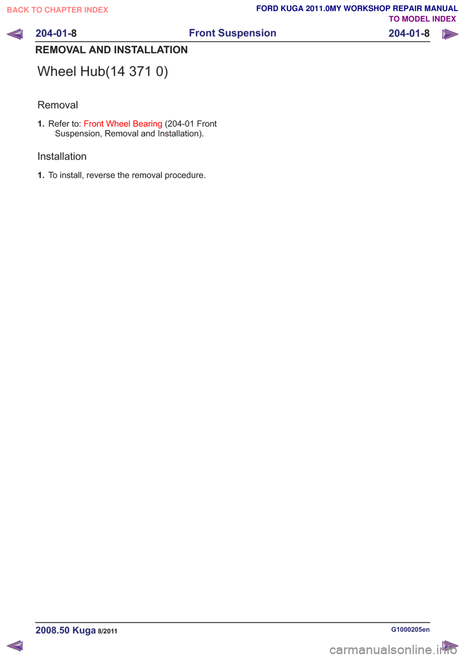
Wheel Hub(14 371 0)
Removal
1.Refer to: Front Wheel Bearing (204-01 Front
Suspension, Removal and Installation).
Installation
1. To install, reverse the removal procedure.
G1000205en2008.50 Kuga8/2011
204-01- 8
Front Suspension
204-01- 8
REMOVAL AND INSTALLATION
TO MODEL INDEX
BACK TO CHAPTER INDEX
FORD KUGA 2011.0MY WORKSHOP REPAIR MANUAL
Page 1180 of 2057
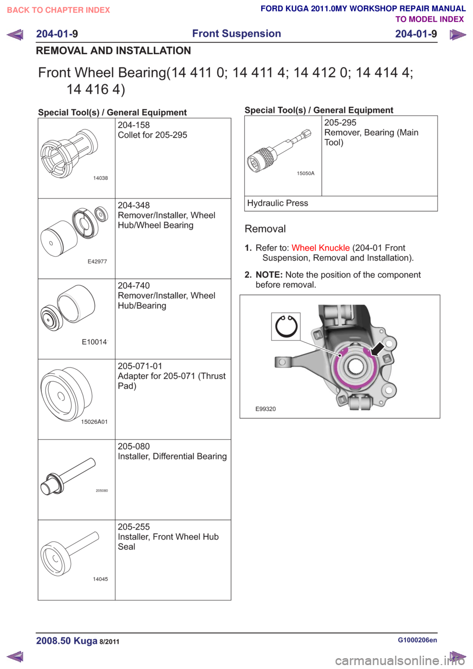
Front Wheel Bearing(14 411 0; 14 411 4; 14 412 0; 14 414 4;14 416 4)
Special Tool(s) / General Equipment
204-158
Collet for 205-295
14038
204-348
Remover/Installer, Wheel
Hub/Wheel Bearing
E42977
204-740
Remover/Installer, Wheel
Hub/Bearing
E100141
205-071-01
Adapter for 205-071 (Thrust
Pad)
15026A01
205-080
Installer, Differential Bearing
205080
205-255
Installer, Front Wheel Hub
Seal
14045
Special Tool(s) / General Equipment205-295
Remover, Bearing (Main
Tool)
15050A
Hydraulic Press
Removal
1.Refer to: Wheel Knuckle (204-01 Front
Suspension, Removal and Installation).
2. NOTE: Note the position of the component
before removal.
E99320
G1000206en2008.50 Kuga8/2011
204-01- 9
Front Suspension
204-01- 9
REMOVAL AND INSTALLATION
TO MODEL INDEX
BACK TO CHAPTER INDEX
FORD KUGA 2011.0MY WORKSHOP REPAIR MANUAL
Page 1195 of 2057
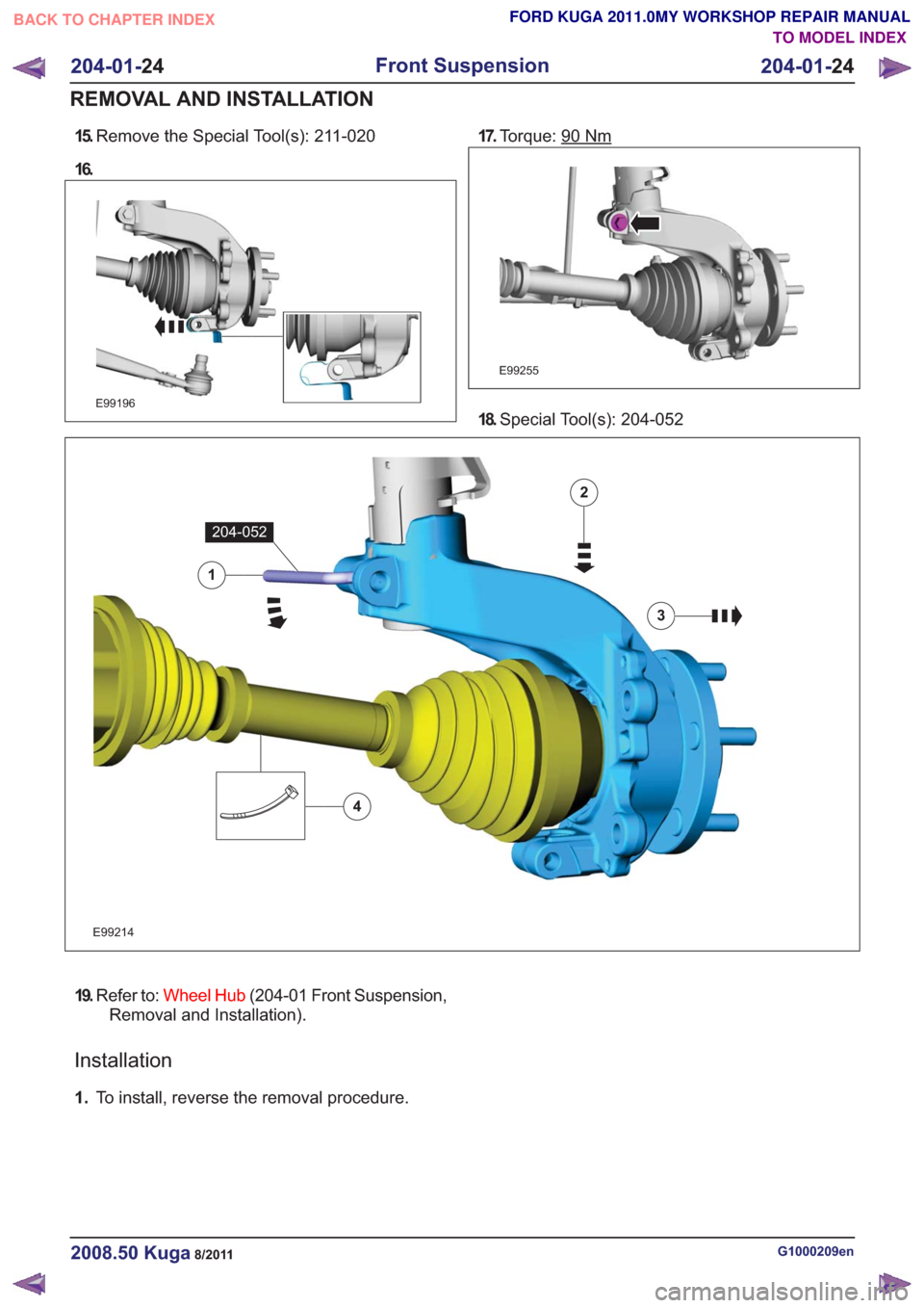
15.Remove the Special Tool(s): 211-020
16.
E99196
17. Torque: 90Nm
E99255
18.Special Tool(s): 204-052
E99214
1
204-052
2
3
4
19.Refer to: Wheel Hub (204-01 Front Suspension,
Removal and Installation).
Installation
1. To install, reverse the removal procedure.
G1000209en2008.50 Kuga8/2011
204-01- 24
Front Suspension
204-01- 24
REMOVAL AND INSTALLATION
TO MODEL INDEX
BACK TO CHAPTER INDEX
FORD KUGA 2011.0MY WORKSHOP REPAIR MANUAL