2011 FORD KUGA etc
[x] Cancel search: etcPage 53 of 2057

Make sure there is adequate ventilation to control
dusts, mists and fumes.
High Pressure Air, Lubrication and Oil
Test Equipment
See alsoLubricants and Greases.
Always keep high-pressure equipment in good
condition, and regularly maintained, particularly at
joints and unions.
Never direct a high-pressure nozzle, for example
diesel injector, at the skin as the fluid may
penetrate to the underlying tissue, and cause
serious injury.
Halon
See CFCs.
Legal Aspects
There are many laws and regulations relating to
health and safety in the use and disposal of
materials and equipment in a workshop.
For a safe working environment and to avoid
environmental pollution, workshops should be
familiar, in detail, with the many health and safety
laws and regulations within their country, published
by both national and local authorities.
Lubricants and Greases
Avoid all prolonged and repeated contact with
mineral oils. All lubricants and greases may be
irritating to the eyes and skin.
Transmission Fluids
Safety instructions
Certain Transmission and Power Steering fluids
supplied to Ford may contain additives which have
the potential to cause skin disease (dermatitis) to
exposed persons. The dermatitis may be irritant
or allergic in nature. Risks are higher where
prolonged or repeated skin contact with a fluid may
occur. These fluids are used for vehicle initial fill
and service purposes. This sub-section is to: • Inform Service personnel who may come into
contact with these vehicle fluids (hazard
communication).
• Summarise appropriate workplace control measures and personal protective equipment
requirements.
• Draw attention to the existence of Material Safety Datasheets (MSDS's) for the fluids
(available from Ford Customer Service Division).
These MSDS's contain detailed information on
hazards and appropriate controls.
Control measures
Workplace risk assessments made under national
chemical control regulations should identify
operations involving the fluids as potentially
hazardous and specify workplace control and
worker awareness measures. In such
circumstances, the relevant Material Safety
Datasheet (see the details specified below) which
specifies hazards and control measures in detail
should be made available for guidance.
Avoid unprotected skin contact with the fluids, and
in particular, avoid prolonged or repeated skin
contact. Work practices should be organised so as
to minimise the potential for skin contact. This may
include the use of drip trays, absorbents, correct
fluid handling equipment (funnels etc), and
workplace housekeeping measures such as the
cleaning of contaminated surfaces.
Personnel engaged in operations where skin
contact could occur (such as fluid draining or filling)
should wear impervious gloves made from nitrile
rubber, certified to a chemical protection standard,
e.g. Europe Standard EN374. This glove type is
widely available from reputable suppliers of gloves
for chemical protection [including the manufacturers
Ansell-Admont (Solvex Range), North Safety
products (North Nitrile Latex Gloves range), and
Marigold Industrial (Blue Nitrile range)]. If gloves
become torn or contaminated on the inside they
should be replaced. Eye protection with safety
glasses is appropriate. Use of an impervious apron
and arm protectors may be necessary if more
extensive exposure is possible. Use of skin barrier
creams suitable for work with mineral oil products
may offer some supplementary protection, but such
barrier creams should not be used in place of
protective clothing.
If accidental skin contact occurs with the fluids,
wash the area thoroughly with soap or skin
cleanser and water.
G566527en2008.50 Kuga8/2011
100-00- 48
General Information
100-00- 48
DESCRIPTION AND OPERATION
TO MODEL INDEX
BACK TO CHAPTER INDEX
FORD KUGA 2011.0MY WORKSHOP REPAIR MANUAL
Page 71 of 2057

Supplemental Restraint System (SRS) Health and SafetyPrecautions
WARNINGS:
Only qualified technicians are allowed to
work on pyrotechnic components.
INHALED: Exposure to pyrotechnic residue
may cause low blood pressure, severe
headache, irritation of mucous membranes,
fainting, shortness of breath or rapid pulse.
Move a victim to fresh air. Seek immediate
medical attention.
EYE CONTACT: Exposure to unburned
pyrotechnic residue may cause irritation,
burning and etching of the eyes. Flush
immediately with plenty of cold running
water for at least 15 minutes. Seek
immediate medical attention.
EYE CONTACT: Exposure to burned
pyrotechnic residue may cause irritation,
burning and etching of the eyes. Flush
immediately with diluted boric acid
solution. Seek immediate medical
attention.
SKIN CONTACT: Unburned pyrotechnic
residue may be rapidly absorbed through
the skin in toxic quantities. Wash
immediately with plenty of soap and water.
Seek medical attention.
SKIN CONTACT: Burned pyrotechnic
residue may be rapidly absorbed through
the skin in toxic quantities. Wash with
plenty of water. Do not use soap. Seek
medical attention.
SWALLOWED: Unburned pyrotechnic
residue is extremely toxic. If conscious
drink plenty of water then induce vomiting.
Seek immediate medical attention. If
unconscious, or in convulsions do not
attempt to induce vomiting or give
anything by mouth. Seek immediate
medical attention.
SWALLOWED: Burned pyrotechnic residue
is extremely toxic. Drink plenty of water
and seek immediate medical attention.
The deployment key must only be
accessible to authorized personnel.
Make sure that the deployment key remains
removed from the deployment equipment
except during deployment.
If permenantly disabling or enabling the
passenger air bag a new seat belt for
vehicles without or with a passenger air
bag must be installed.
Undeployed pyrotechnic components must
not be deployed in the vehicle.
Pyrotechnic components must be deployed
following local regulations.
Check thoroughly that no loose objects
can be spread during the deployment of
pyrotechnic components.
Pyrotechnic components must be
transported following local regulations.
Never carry out any electrical measurement
on disconnected, undeployed pyrotechnic
components.
Pyrotechnic components must not be
disassembled.
Pyrotechnic components are not
interchangeable between vehicles.
Always carry a live air bag module away
from the body with the air bag or trim cover
pointing upwards.
Live air bag modules must be placed in a
suitable cage when removed from the
vehicle. The air bag or trim cover must be
facing upwards.
Do not install a rearward facing child safety
seat to the passenger seat with an
activated passenger air bag.
CAUTIONS:
Pyrotechnic components must not be
subjected to temperatures higher than
110°C.
Never install aftermarket accessories to
the vehicle on or adjacent to the
supplemental restraint system module.
G548998en2008.50 Kuga8/2011
100-00- 65
General Information
100-00- 65
DESCRIPTION AND OPERATION
TO MODEL INDEX
BACK TO CHAPTER INDEX
FORD KUGA 2011.0MY WORKSHOP REPAIR MANUAL
Page 1530 of 2057
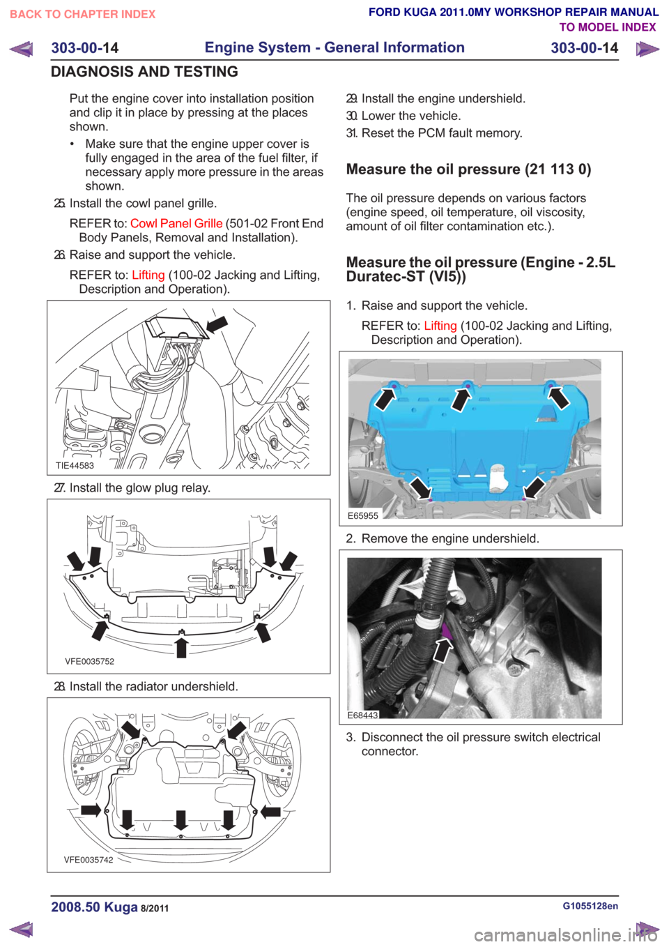
Put the engine cover into installation position
and clip it in place by pressing at the places
shown.• Make sure that the engine upper cover is fully engaged in the area of the fuel filter, if
necessary apply more pressure in the areas
shown.
25. Install the cowl panel grille.
REFER to: Cowl Panel Grille (501-02 Front End
Body Panels, Removal and Installation).
26. Raise and support the vehicle.
REFER to: Lifting(100-02 Jacking and Lifting,
Description and Operation).
TIE44583
27. Install the glow plug relay.
VFE0035752
28. Install the radiator undershield.
VFE0035742
29. Install the engine undershield.
30. Lower the vehicle.
31. Reset the PCM fault memory.
Measure the oil pressure (21 113 0)
The oil pressure depends on various factors
(engine speed, oil temperature, oil viscosity,
amount of oil filter contamination etc.).
Measure the oil pressure (Engine - 2.5L
Duratec-ST (VI5))
1. Raise and support the vehicle.
REFER to: Lifting(100-02 Jacking and Lifting,
Description and Operation).
E65955
2. Remove the engine undershield.
E68443
3. Disconnect the oil pressure switch electrical connector.
G1055128en2008.50 Kuga8/2011
303-00- 14
Engine System - General Information
303-00- 14
DIAGNOSIS AND TESTING
TO MODEL INDEX
BACK TO CHAPTER INDEX
FORD KUGA 2011.0MY WORKSHOP REPAIR MANUAL
Page 1700 of 2057
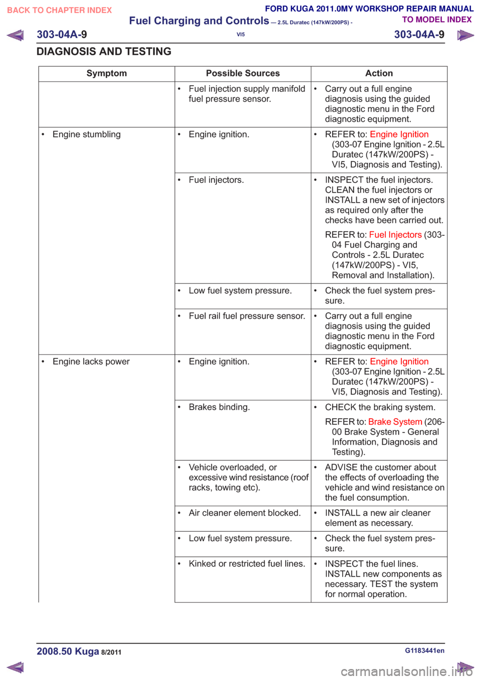
Action
Possible Sources
Symptom
• Carry out a full enginediagnosis using the guided
diagnostic menu in the Ford
diagnostic equipment.
• Fuel injection supply manifold
fuel pressure sensor.
• REFER to:Engine Ignition
(303-07 Engine Ignition - 2.5L
Duratec (147kW/200PS) -
VI5, Diagnosis and Testing).
• Engine ignition.
• Engine stumbling
• INSPECT the fuel injectors.CLEAN the fuel injectors or
INSTALL a new set of injectors
as required only after the
checks have been carried out.
REFER to: Fuel Injectors (303-
04 Fuel Charging and
Controls - 2.5L Duratec
(147kW/200PS) - VI5,
Removal and Installation).
• Fuel injectors.
• Check the fuel system pres-sure.
• Low fuel system pressure.
• Carry out a full enginediagnosis using the guided
diagnostic menu in the Ford
diagnostic equipment.
• Fuel rail fuel pressure sensor.
• REFER to:Engine Ignition
(303-07 Engine Ignition - 2.5L
Duratec (147kW/200PS) -
VI5, Diagnosis and Testing).
• Engine ignition.
• Engine lacks power
• CHECK the braking system.REFER to: Brake System (206-
00 Brake System - General
Information, Diagnosis and
Testing).
• Brakes binding.
• ADVISE the customer aboutthe effects of overloading the
vehicle and wind resistance on
the fuel consumption.
• Vehicle overloaded, or
excessive wind resistance (roof
racks, towing etc).
• INSTALL a new air cleanerelement as necessary.
• Air cleaner element blocked.
• Check the fuel system pres-sure.
• Low fuel system pressure.
• INSPECT the fuel lines.INSTALL new components as
necessary. TEST the system
for normal operation.
• Kinked or restricted fuel lines.
G1183441en2008.50 Kuga8/2011
303-04A-
9
Fuel Charging and Controls
— 2.5L Duratec (147kW/200PS) -
VI5
303-04A- 9
DIAGNOSIS AND TESTING
TO MODEL INDEX
BACK TO CHAPTER INDEX
FORD KUGA 2011.0MY WORKSHOP REPAIR MANUAL
Page 1710 of 2057
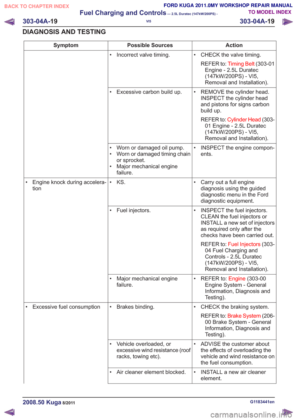
Action
Possible Sources
Symptom
• CHECK the valve timing.REFER to: Timing Belt (303-01
Engine - 2.5L Duratec
(147kW/200PS) - VI5,
Removal and Installation).
• Incorrect valve timing.
• REMOVE the cylinder head.INSPECT the cylinder head
and pistons for signs carbon
build up.
REFER to: Cylinder Head (303-
01 Engine - 2.5L Duratec
(147kW/200PS) - VI5,
Removal and Installation).
• Excessive carbon build up.
• INSPECT the engine compon-ents.
• Worn or damaged oil pump.
• Worn or damaged timing chain
or sprocket.
• Major mechanical engine failure.
• Carry out a full enginediagnosis using the guided
diagnostic menu in the Ford
diagnostic equipment.
• KS.
• Engine knock during accelera-
tion
• INSPECT the fuel injectors.CLEAN the fuel injectors or
INSTALL a new set of injectors
as required only after the
checks have been carried out.
REFER to: Fuel Injectors (303-
04 Fuel Charging and
Controls - 2.5L Duratec
(147kW/200PS) - VI5,
Removal and Installation).
• Fuel injectors.
• REFER to:Engine(303-00
Engine System - General
Information, Diagnosis and
Testing).
• Major mechanical engine
failure.
• CHECK the braking system.REFER to: Brake System (206-
00 Brake System - General
Information, Diagnosis and
Testing).
• Brakes binding.
• Excessive fuel consumption
• ADVISE the customer aboutthe effects of overloading the
vehicle and wind resistance on
the fuel consumption.
• Vehicle overloaded, or
excessive wind resistance (roof
racks, towing etc).
• INSTALL a new air cleanerelement.
• Air cleaner element blocked.
G1183441en2008.50 Kuga8/2011
303-04A-
19
Fuel Charging and Controls
— 2.5L Duratec (147kW/200PS) -
VI5
303-04A- 19
DIAGNOSIS AND TESTING
TO MODEL INDEX
BACK TO CHAPTER INDEX
FORD KUGA 2011.0MY WORKSHOP REPAIR MANUAL
Page 1828 of 2057
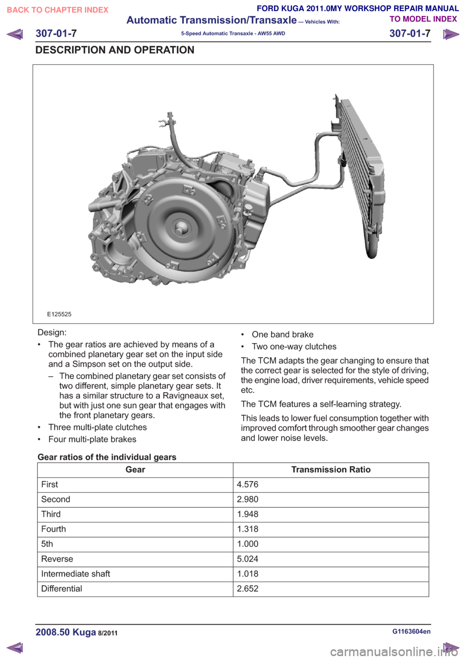
E125525
Design:
• The gear ratios are achieved by means of acombined planetary gear set on the input side
and a Simpson set on the output side.
– The combined planetary gear set consists oftwo different, simple planetary gear sets. It
has a similar structure to a Ravigneaux set,
but with just one sun gear that engages with
the front planetary gears.
• Three multi-plate clutches
• Four multi-plate brakes • One band brake
• Two one-way clutches
The TCM adapts the gear changing to ensure that
the correct gear is selected for the style of driving,
the engine load, driver requirements, vehicle speed
etc.
The TCM features a self-learning strategy.
This leads to lower fuel consumption together with
improved comfort through smoother gear changes
and lower noise levels.
Gear ratios of the individual gears
Transmission Ratio
Gear
4.576
First
2.980
Second
1.948
Third
1.318
Fourth
1.000
5th
5.024
Reverse
1.018
Intermediate shaft
2.652
Differential
G1163604en2008.50 Kuga8/2011
307-01- 7
Automatic Transmission/Transaxle
— Vehicles With:
5-Speed Automatic Transaxle - AW55 AWD
307-01- 7
DESCRIPTION AND OPERATION
TO MODEL INDEX
BACK TO CHAPTER INDEX
FORD KUGA 2011.0MY WORKSHOP REPAIR MANUAL
Page 1838 of 2057
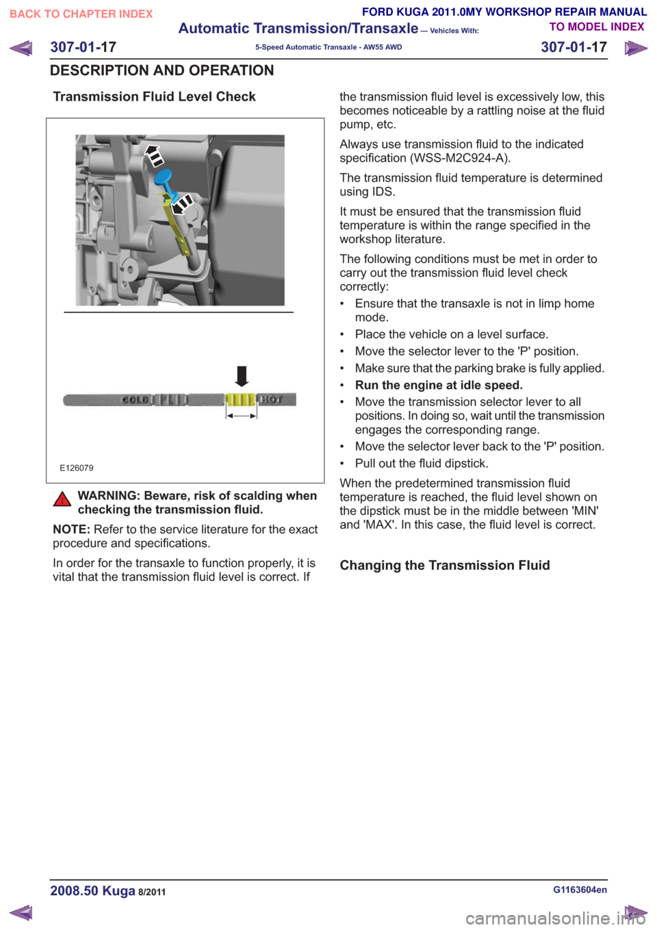
Transmission Fluid Level Check
E126079
WARNING: Beware, risk of scalding when
checking the transmission fluid.
NOTE: Refer to the service literature for the exact
procedure and specifications.
In order for the transaxle to function properly, it is
vital that the transmission fluid level is correct. If the transmission fluid level is excessively low, this
becomes noticeable by a rattling noise at the fluid
pump, etc.
Always use transmission fluid to the indicated
specification (WSS-M2C924-A).
The transmission fluid temperature is determined
using IDS.
It must be ensured that the transmission fluid
temperature is within the range specified in the
workshop literature.
The following conditions must be met in order to
carry out the transmission fluid level check
correctly:
• Ensure that the transaxle is not in limp home
mode.
• Place the vehicle on a level surface.
• Move the selector lever to the 'P' position.
• Make sure that the parking brake is fully applied.
• Run the engine at idle speed.
• Move the transmission selector lever to all positions. In doing so, wait until the transmission
engages the corresponding range.
• Move the selector lever back to the 'P' position.
• Pull out the fluid dipstick.
When the predetermined transmission fluid
temperature is reached, the fluid level shown on
the dipstick must be in the middle between 'MIN'
and 'MAX'. In this case, the fluid level is correct.
Changing the Transmission Fluid
G1163604en2008.50 Kuga8/2011
307-01- 17
Automatic Transmission/Transaxle
— Vehicles With:
5-Speed Automatic Transaxle - AW55 AWD
307-01- 17
DESCRIPTION AND OPERATION
TO MODEL INDEX
BACK TO CHAPTER INDEX
FORD KUGA 2011.0MY WORKSHOP REPAIR MANUAL
Page 1839 of 2057
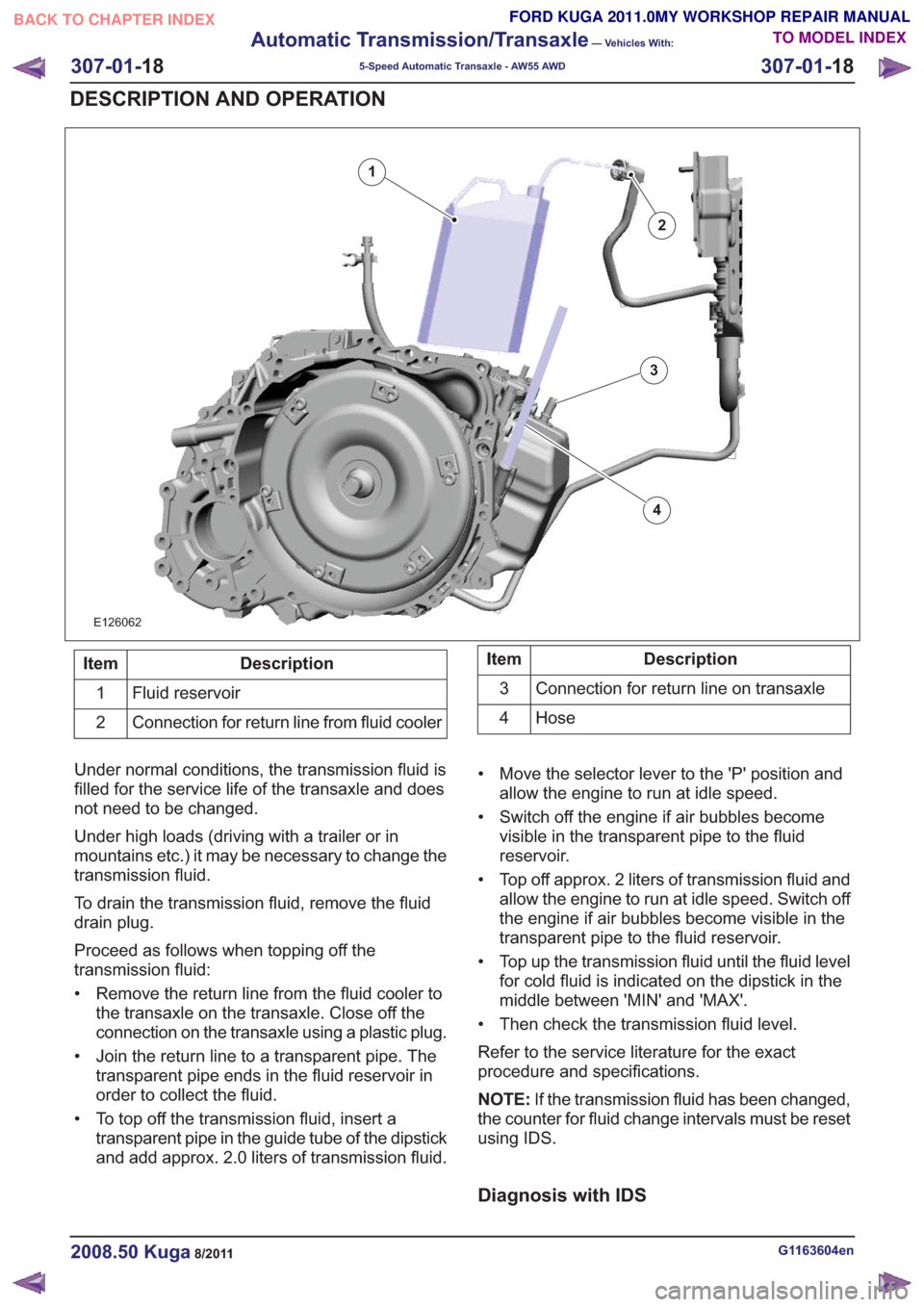
E126062
2
1
3
4
Description
Item
Fluid reservoir
1
Connection for return line from fluid cooler
2Description
Item
Connection for return line on transaxle
3
Hose
4
Under normal conditions, the transmission fluid is
filled for the service life of the transaxle and does
not need to be changed.
Under high loads (driving with a trailer or in
mountains etc.) it may be necessary to change the
transmission fluid.
To drain the transmission fluid, remove the fluid
drain plug.
Proceed as follows when topping off the
transmission fluid:
• Remove the return line from the fluid cooler to the transaxle on the transaxle. Close off the
connection on the transaxle using a plastic plug.
• Join the return line to a transparent pipe. The transparent pipe ends in the fluid reservoir in
order to collect the fluid.
• To top off the transmission fluid, insert a transparent pipe in the guide tube of the dipstick
and add approx. 2.0 liters of transmission fluid. • Move the selector lever to the 'P' position and
allow the engine to run at idle speed.
• Switch off the engine if air bubbles become visible in the transparent pipe to the fluid
reservoir.
• Top off approx. 2 liters of transmission fluid and allow the engine to run at idle speed. Switch off
the engine if air bubbles become visible in the
transparent pipe to the fluid reservoir.
• Top up the transmission fluid until the fluid level for cold fluid is indicated on the dipstick in the
middle between 'MIN' and 'MAX'.
• Then check the transmission fluid level.
Refer to the service literature for the exact
procedure and specifications.
NOTE: If the transmission fluid has been changed,
the counter for fluid change intervals must be reset
using IDS.
Diagnosis with IDS
G1163604en2008.50 Kuga8/2011
307-01- 18
Automatic Transmission/Transaxle
— Vehicles With:
5-Speed Automatic Transaxle - AW55 AWD
307-01- 18
DESCRIPTION AND OPERATION
TO MODEL INDEX
BACK TO CHAPTER INDEX
FORD KUGA 2011.0MY WORKSHOP REPAIR MANUAL