2011 FORD KUGA Plug
[x] Cancel search: PlugPage 52 of 2057

dermatitis or be absorbed through the skin in
toxic or harmful quantities.
– Do not use emptied containers for other materials except when they have been cleaned
under supervised conditions.
– Do not sniff or smell chemical materials. Brief exposure to high concentrations of fumes can
be toxic or harmful.
Chlorofluorocarbons (CFC)
There is concern in the scientific community that
CFCs and Halons are depleting the upper ozone
layer which filters out harmful ultraviolet radiation.
Decreased filtration of ultraviolet radiation may
result in increases in skin cancer, cataracts and
immune system suppression in humans, as well
as decreased productivity of crops and aquatic
systems.
CFCs are used primarily as refrigerants in vehicle
air conditioning systems and as aerosol
propellants. Halons are used as fire extinguishants.
Clutch Fluids
See Brake fluids.
Clutch Linings and Pads
SeeAsbestos.
Corrosion Protection Materials
See also Solvents, Fire.
Highly flammable, flammable – observe No
Smoking policy.
These materials are varied and the manufacturers
instructions must be followed. They may contain
solvents, resins or petroleum products. Skin and
eye contact should be avoided. They should only
be sprayed in conditions of adequate ventilation
and not in confined spaces.
Cutting
See Welding.
Dewaxing
SeeSolvents andFuels (Kerosene).
Dusts
Powder, dusts or clouds may be irritant, harmful
or toxic. Avoid breathing dusts from powdery
chemical materials or those arising from dry
abrasion operations. Wear respiratory protection
if ventilation is inadequate.
Fine dusts of combustible material can present an
explosion hazard. Avoid explosive limits and
sources of ignition.
Electric Shock
Electric shock can result from the use of faulty
electrical equipment or from the misuse of
equipment in good condition.
Make sure that electrical equipment is maintained
in good condition and frequently tested. Faulty
equipment should be labeled and preferably
removed from the workstation.
Make sure that flexes, cables, plugs and sockets
are not frayed, kinked, cut, cracked or otherwise
damaged.
Make sure that electrical equipment and flexes do
not come into contact with water.
Make sure that electrical equipment is protected
by the correct rated fuse.
Never misuse electrical equipment and never use
equipment that is in any way faulty. The results
could be fatal.
Make sure that the cables of mobile electrical
equipment cannot get trapped and damaged, such
as in a vehicle hoist.
Make sure that the designated electrical workers
are trained in basic First Aid.
In cases of electrocution:
– switch off the power supply before approaching
the victim.
– if this is not possible push or drag the victim from the source of electricity using dry
non-conductive material.
– commence resuscitation if trained to do so.
– SUMMON MEDICAL ASSISTANCE.
Engine Oils
See Lubricants and Grease.
G566527en2008.50 Kuga8/2011
100-00- 45
General Information
100-00- 45
DESCRIPTION AND OPERATION
TO MODEL INDEX
BACK TO CHAPTER INDEX
FORD KUGA 2011.0MY WORKSHOP REPAIR MANUAL
Page 60 of 2057

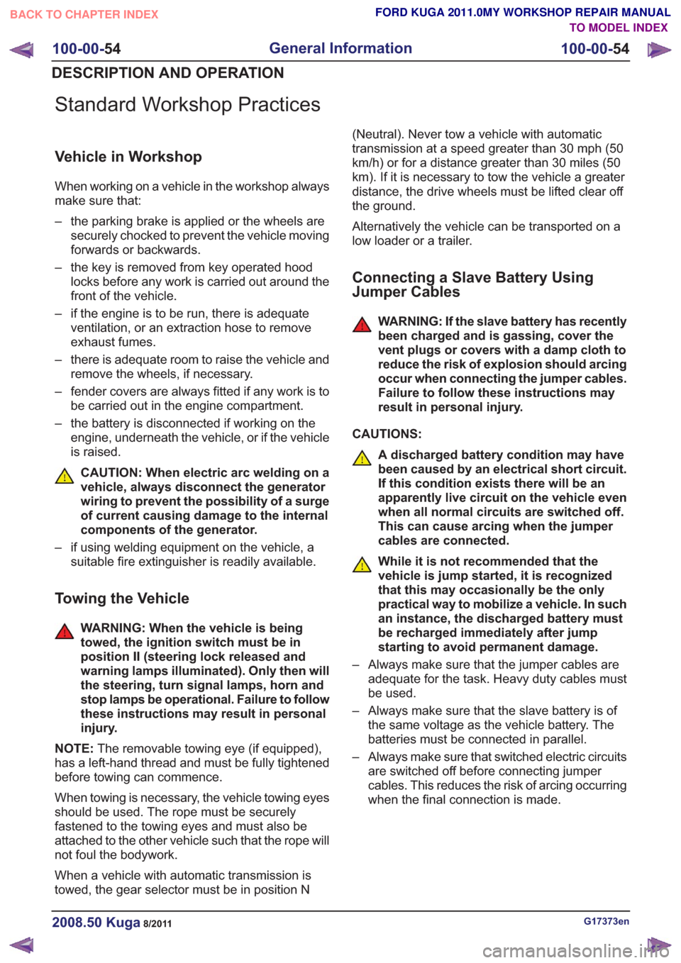
Standard Workshop Practices
Vehicle in Workshop
When working on a vehicle in the workshop always
make sure that:
– the parking brake is applied or the wheels aresecurely chocked to prevent the vehicle moving
forwards or backwards.
– the key is removed from key operated hood locks before any work is carried out around the
front of the vehicle.
– if the engine is to be run, there is adequate ventilation, or an extraction hose to remove
exhaust fumes.
– there is adequate room to raise the vehicle and remove the wheels, if necessary.
– fender covers are always fitted if any work is to be carried out in the engine compartment.
– the battery is disconnected if working on the engine, underneath the vehicle, or if the vehicle
is raised.
CAUTION: When electric arc welding on a
vehicle, always disconnect the generator
wiring to prevent the possibility of a surge
of current causing damage to the internal
components of the generator.
– if using welding equipment on the vehicle, a suitable fire extinguisher is readily available.
Towing the Vehicle
WARNING: When the vehicle is being
towed, the ignition switch must be in
position II (steering lock released and
warning lamps illuminated). Only then will
the steering, turn signal lamps, horn and
stop lamps be operational. Failure to follow
these instructions may result in personal
injury.
NOTE: The removable towing eye (if equipped),
has a left-hand thread and must be fully tightened
before towing can commence.
When towing is necessary, the vehicle towing eyes
should be used. The rope must be securely
fastened to the towing eyes and must also be
attached to the other vehicle such that the rope will
not foul the bodywork.
When a vehicle with automatic transmission is
towed, the gear selector must be in position N (Neutral). Never tow a vehicle with automatic
transmission at a speed greater than 30 mph (50
km/h) or for a distance greater than 30 miles (50
km). If it is necessary to tow the vehicle a greater
distance, the drive wheels must be lifted clear off
the ground.
Alternatively the vehicle can be transported on a
low loader or a trailer.
Connecting a Slave Battery Using
Jumper Cables
WARNING: If the slave battery has recently
been charged and is gassing, cover the
vent plugs or covers with a damp cloth to
reduce the risk of explosion should arcing
occur when connecting the jumper cables.
Failure to follow these instructions may
result in personal injury.
CAUTIONS:
A discharged battery condition may have
been caused by an electrical short circuit.
If this condition exists there will be an
apparently live circuit on the vehicle even
when all normal circuits are switched off.
This can cause arcing when the jumper
cables are connected.
While it is not recommended that the
vehicle is jump started, it is recognized
that this may occasionally be the only
practical way to mobilize a vehicle. In such
an instance, the discharged battery must
be recharged immediately after jump
starting to avoid permanent damage.
– Always make sure that the jumper cables are adequate for the task. Heavy duty cables must
be used.
– Always make sure that the slave battery is of the same voltage as the vehicle battery. The
batteries must be connected in parallel.
– Always make sure that switched electric circuits are switched off before connecting jumper
cables. This reduces the risk of arcing occurring
when the final connection is made.
G17373en2008.50 Kuga8/2011
100-00- 54
General Information
100-00- 54
DESCRIPTION AND OPERATION
TO MODEL INDEX
BACK TO CHAPTER INDEX
FORD KUGA 2011.0MY WORKSHOP REPAIR MANUAL
Page 74 of 2057

E59517
Description
Item
Activated charcoal filter
1
Coarse filter
2
Filter masks with wadding, sponge or colloid filters
and also paper masks are all unsuitable for working
with coating materials because they do not stop
solvent vapors.
Eye protection
Cutting grinding welding solvents and paint bear
fundamental risks for your eyes.
Damage ranging from irritation of the cornea to
incurable illnesses is possible.
Solvents and paint – even water based – could not
only be absorbed via your skin but also via your
eyes.
Therefore always wear the appropriate eye
protection for your work.
Protective goggles must be inert toward splashes
of solvent, and must have side protection. Best
protection during spray painting is offered by full
mask respirators or helmet respirators with built-in
visor.
Skin protection
Spray painters must wear suitable protective work
clothing (flame-proof and anti-static). Also, when
working with water based materials, comprehensive
skin protection must be worn, because these
materials are very easily absorbed through the
skin.
Change your protective clothing at proper intervals.
Clothes contaminated with coating materials can
easily catch fire.
Do not choose clothes or underwear with a large
content of easy melting synthetic fiber, because
this material considerably increases the danger
and degree of injuries (melted plastic on the skin!). For areas of the skin which are not covered by
protective clothing suitable skin protection cleaning
and care agents must be used.
Ear protection
Cutting grinding compressors and extractor fans
and ducts are the main sources of noise in body
and paint shops.
Always wear suitable ear protection like ear plugs
or ear defenders.
Protection of the vehicle
Protect affected areas from weld spatter and dust
during all welding and grinding work on the vehicle.
If metallic dust stays on the vehicle for some time,
there is the likelihood of film rust formation.
Grinding produces tiny spots of damage to the paint
surface, which may cause corrosion. Also use
suitable protective measures to protect the interior
when performing repair operations which relate to
the inside of the vehicle.
For this reason, make sure to:
• Use carbon fiber blankets to protect the vehicle
body and the interior.
• Use covering film to protect the vehicle body from grinding dust and metal dust.
• Use covering paper to protect the interior from grinding dust.
In addition, take into account:
• Remove fuel supply components as necessary.
• Protect working areas which are in danger of catching fire with a fireproof blanket.
• Keep heat away from all components of the air conditioning system.
• Remove all components in the space adjoining the repair area.
Electronic components
Increased use of comfort and safety electronics in
modern vehicles requires additional attention to be
paid during body work.
Over voltages produced during welding can cause
electronic systems to be damaged. In particular,
the safety instructions for performing welding work
on vehicles with airbag systems must be adhered
to.
WARNING: After disconnecting the power
supply and before performing further work,
a wait time of up to 15 minutes must be
G963390en2008.50 Kuga8/2011
100-00- 69
General Information
100-00- 69
DESCRIPTION AND OPERATION
TO MODEL INDEX
BACK TO CHAPTER INDEX
FORD KUGA 2011.0MY WORKSHOP REPAIR MANUAL
Page 166 of 2057

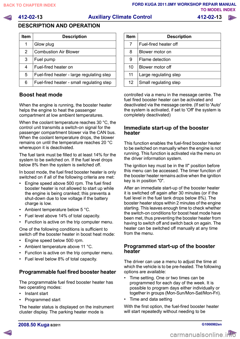
Description
Item
Glow plug
1
Combustion Air Blower
2
Fuel pump
3
Fuel-fired heater on
4
Fuel-fired heater - large regulating step
5
Fuel-fired heater - small regulating step
6 Description
Item
Fuel-fired heater off
7
Blower motor on
8
Flame detection
9
Blower motor off
10
Large regulating step
11
Small regulating step
12
Boost heat mode
When the engine is running, the booster heater
helps the engine to heat the passenger
compartment at low ambient temperatures.
When the coolant temperature reaches 30 °C, the
control unit transmits a switch-on signal for the
passenger compartment blower via the CAN bus.
When the coolant temperature drops, the blower
remains on until the temperature reaches 20 °C
whereupon it is deactivated.
The fuel tank must be filled to at least 14% for the
system to be switched on. If the fuel level drops
below 8% then the system is switched off.
In boost mode, the fuel fired booster heater is only
switched on if all of the following criteria are met:
• Engine speed above 500 rpm. The fuel fired booster heater is not allowed to start up while
the engine is being cranked; this prevents a
shut-down due to low voltage if the battery
charge is low.
• Ambient temperature below 5 °C.
• Fuel level above 14% of total capacity.
• Function is active on the trip computer menu.
One of the following conditions is sufficient to
switch off the booster heater in boost heat mode:
• Engine speed below 500 rpm.
• Ambient temperature above 11 °C.
• Function is active on the trip computer menu.
• Fuel level below 8% of total capacity.
Programmable fuel fired booster heater
The programmable fuel fired booster heater has
two operating modes:
• Instant start
• Programmed start
The heater status is displayed on the instrument
cluster display. The parking heater mode is controlled via a menu in the message centre. The
fuel fired booster heater can be activated and
deactivated via the message centre. (If set to 'Auto'
the system is activated, if set to 'Off' the system is
completely deactivated)
Immediate start-up of the booster
heater
This function enables the fuel-fired booster heater
to be switched on manually when the engine is not
running. This function is activated via the menu on
the driver information system.
The ignition key must be in the II" position before
this menu can be accessed. The timer function of
the booster heater remains active when the ignition
key is in position "0".
After an immediate start-up of the booster heater
it is switched off again after 30 minutes (or if the
fuel level in the fuel tank drops below 8%). The
booster heater stops within 2 minutes of the engine
starting. This leaves enough time to check whether
the switch-on conditions for boost heat mode have
been met, thus preventing the booster heater from
having to switch off and switch back on again. The
heater can be switched off manually at any time
from the menu.
Programmed start-up of the booster
heater
The driver can use a menu to adjust the time at
which the vehicle is to be pre-heated. The following
options are available:
• Time setting. One or two times can be
programmed for each day of the week. It is
possible to program days either individually or
together in groups (Mon-Sun/Mon-Sat/Mon-Fri).
• Time and data setting
With the first option, the fuel-fired booster heater
will start repeatedly without needing to be G1066982en
2008.50 Kuga 8/2011 412-02-13
Auxiliary Climate Control
412-02-13
DESCRIPTION AND OPERATIONTO MODEL INDEX
BACK TO CHAPTER INDEX
FORD KUGA 2011.0MY WORKSHOP REPAIR MANUAL
Page 167 of 2057

reprogrammed. However, if the engine hasn't been
run since the last programmed start, the fuel-fired
booster heater will not start up the second time so
as to prevent the battery from being discharged.
The length of time required to pre-heat the vehicle
is calculated in the control unit of the fuel-fired
booster heater and is based on two temperature
values:
• Ambient air temperature: this message is taken
from the GEM via the CAN bus.
• Coolant temperature: this is determined via an internal sensor in the fuel-fired booster heater.
The maximum heating time is 30 minutes at an
outside air temperature of -10 °C or lower. The
heating time decreases proportionally with
increasing ambient temperature until the ambient
temperature is between +15 °C and +20 °C. Then
the minimum heating time is 10 minutes. The
parking heater is deactivated at temperatures
above +20 °C.
The sequence for a programmed start of the
booster heater is as follows:
• Two minutes before the start of the maximum heating time the driver information
system/instrument cluster sends an activation
message to the fuel-fired booster heater via the
CAN bus.
• The fuel-fired booster heater calculates the required heating time and, if necessary, sends
a delay request on the CAN bus.
• At the calculated time, the fuel-fired booster heater starts up. The conditions for start-up are:
engine not running and amount of fuel in the
fuel tank is above 14% of maximum.
• When the coolant temperature reaches +30 °C, the control unit of the fuel-fired booster heater
sends a request to switch on the passenger
compartment blower.
• Eight minutes after the programmed switch-off time, the booster heater stops heating mode
and starts a run-on operation to clean the
system's spark plugs.
• Ten minutes after the switch-off time, the post-cleaning operation is complete. The
additional ten minutes run-on time provides
some leeway in case the driver is late arriving.
After a programmed start-up of the booster heater
it is switched off again after the heating time has
elapsed (or if the fuel level in the fuel tank drops
below 8%). The booster heater stops within 2 minutes of the engine starting. This leaves enough
time to check whether the switch-on conditions for
boost heat mode have been met, thus preventing
the booster heater from having to switch off and
switch back on again. The heater can be switched
off manually at any time from the menu.
Whilst the fuel-fired booster heater is in additional
heating mode and/or parking heating mode, the
instrument cluster receives a fuel consumption
signal; this is used to re-calculate the vehicle's
remaining range and fuel consumption data.
Emergency shutoff
In the event of an accident in which the airbags
are deployed, the control unit of the fuel-fired
booster heater receives a message on the CAN
bus from the restraints control module (RCM).
When this message is received, the booster heater
system switches off immediately.
The booster heater control module deactivates the
system and does not respond to further messages
on the CAN bus. The booster heater control module
needs to be activated with WDS.
Component Description
Electric Booster Heater
The electric booster heater consists of three
individual heating elements, which are incorporated
into a single housing. It is controlled by the generic
electronic module (GEM), taking into account the
following factors:
Detailed illustration of fuel-fired heater
G1066982en
2008.50 Kuga 8/2011 412-02-14
Auxiliary Climate Control
412-02-14
DESCRIPTION AND OPERATIONTO MODEL INDEX
BACK TO CHAPTER INDEX
FORD KUGA 2011.0MY WORKSHOP REPAIR MANUALE97621
Page 168 of 2057

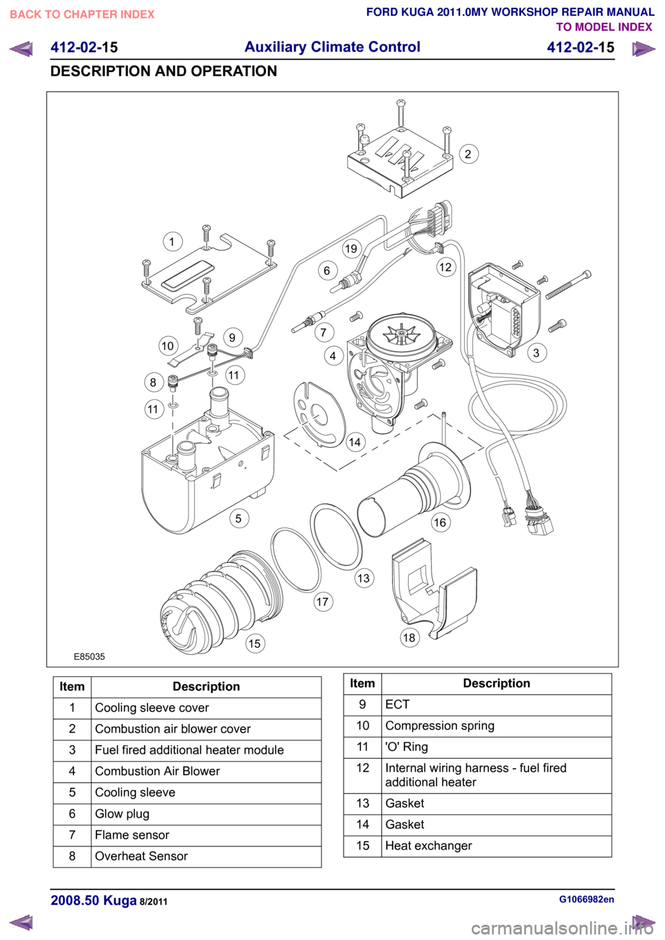
Description
Item
Cooling sleeve cover
1
Combustion air blower cover
2
Fuel fired additional heater module
3
Combustion Air Blower
4
Cooling sleeve
5
Glow plug
6
Flame sensor
7
Overheat Sensor
8 Description
Item
ECT9
Compression spring
10
'O' Ring
11
Internal wiring harness - fuel fired
additional heater
12
Gasket
13
Gasket
14
Heat exchanger
15 G1066982en
2008.50 Kuga 8/2011 412-02-15
Auxiliary Climate Control
412-02-15
DESCRIPTION AND OPERATIONTO MODEL INDEX
BACK TO CHAPTER INDEX
FORD KUGA 2011.0MY WORKSHOP REPAIR MANUALE850351132126791011115144316171518198
Page 169 of 2057

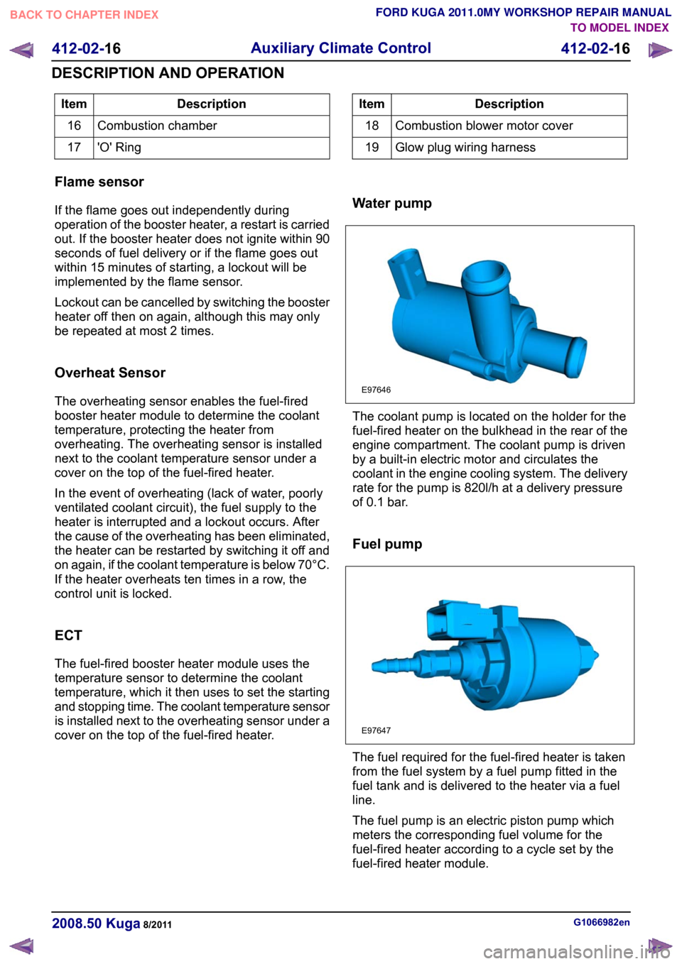
Description
Item
Combustion chamber
16
'O' Ring
17 Description
Item
Combustion blower motor cover
18
Glow plug wiring harness
19
Flame sensor
If the flame goes out independently during
operation of the booster heater, a restart is carried
out. If the booster heater does not ignite within 90
seconds of fuel delivery or if the flame goes out
within 15 minutes of starting, a lockout will be
implemented by the flame sensor.
Lockout can be cancelled by switching the booster
heater off then on again, although this may only
be repeated at most 2 times.
Overheat Sensor
The overheating sensor enables the fuel-fired
booster heater module to determine the coolant
temperature, protecting the heater from
overheating. The overheating sensor is installed
next to the coolant temperature sensor under a
cover on the top of the fuel-fired heater.
In the event of overheating (lack of water, poorly
ventilated coolant circuit), the fuel supply to the
heater is interrupted and a lockout occurs. After
the cause of the overheating has been eliminated,
the heater can be restarted by switching it off and
on again, if the coolant temperature is below 70°C.
If the heater overheats ten times in a row, the
control unit is locked.
ECT
The fuel-fired booster heater module uses the
temperature sensor to determine the coolant
temperature, which it then uses to set the starting
and stopping time. The coolant temperature sensor
is installed next to the overheating sensor under a
cover on the top of the fuel-fired heater. Water pump The coolant pump is located on the holder for the
fuel-fired heater on the bulkhead in the rear of the
engine compartment. The coolant pump is driven
by a built-in electric motor and circulates the
coolant in the engine cooling system. The delivery
rate for the pump is 820l/h at a delivery pressure
of 0.1 bar.
Fuel pump
The fuel required for the fuel-fired heater is taken
from the fuel system by a fuel pump fitted in the
fuel tank and is delivered to the heater via a fuel
line.
The fuel pump is an electric piston pump which
meters the corresponding fuel volume for the
fuel-fired heater according to a cycle set by the
fuel-fired heater module.
G1066982en
2008.50 Kuga 8/2011 412-02-16
Auxiliary Climate Control
412-02-16
DESCRIPTION AND OPERATIONTO MODEL INDEX
BACK TO CHAPTER INDEX
FORD KUGA 2011.0MY WORKSHOP REPAIR MANUALE97646 E97647
Page 279 of 2057

Direct Current/Alternating Current (DC/AC) Inverter – Overview
Function indicator
WARNING: For workshop repairs, it is only
permissible to replace the converter as a
complete unit together with the wiring
harness and the socket. The component
must not be opened, as charged capacitors
inside can still carry dangerously high
residual voltages.
The LED in the socket lights up orange when the
converter is supplying a voltage.
In the event of a fault the system switches off and
indicates the cause of the fault by flashing a trouble
code via the LED in the socket:
• 1x flash – High temperature
• 2x flashes – Overload
• 3x flashes – Internal overvoltage
• 4x flashes – Internal undervoltage
• Continuous flashing – Short circuit to power
If the converter switches off due to high
temperature then it switches back on again
automatically once the temperature has cooled
down sufficiently.
With all of the other faults which are displayed, the
converter can be reset by switching the ignition off
and back on again or by unplugging and reinserting
the consumer in the socket.
If these measures are unsuccessful then there are
no further options for directly influencing the
function yourself. G1055637en
2008.50 Kuga 8/2011 414-05-3
Voltage Converter/Inverter
414-05-3
DESCRIPTION AND OPERATIONTO MODEL INDEX
BACK TO CHAPTER INDEX
FORD KUGA 2011.0MY WORKSHOP REPAIR MANUAL