2011 FORD KUGA connector
[x] Cancel search: connectorPage 1753 of 2057
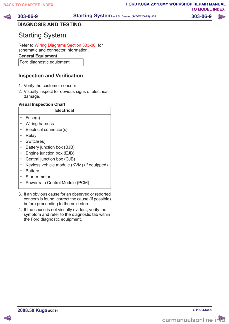
Starting System
Refer toWiring Diagrams Section 303-06, for
schematic and connector information.
General Equipment
Ford diagnostic equipment
Inspection and Verification
1. Verify the customer concern.
2. Visually inspect for obvious signs of electrical damage.
Visual Inspection Chart
Electrical
• Fuse(s)
• Wiring harness
• Electrical connector(s)
• Relay
• Switch(es)
• Battery junction box (BJB)
• Engine junction box (EJB)
• Central junction box (CJB)
• Keyless vehicle module (KVM) (if equipped)
• Battery
• Starter motor
• Powertrain Control Module (PCM)
3. If an obvious cause for an observed or reported concern is found, correct the cause (if possible)
before proceeding to the next step.
4. If the cause is not visually evident, verify the symptom and refer to the diagnostictab within
the Ford diagnostic equipment .
G1183444en2008.50 Kuga8/2011
303-06-9
Starting System— 2.5L Duratec (147kW/200PS) - VI5303-06-
9
DIAGNOSIS AND TESTING
TO MODEL INDEX
BACK TO CHAPTER INDEX
FORD KUGA 2011.0MY WORKSHOP REPAIR MANUAL
Page 1758 of 2057
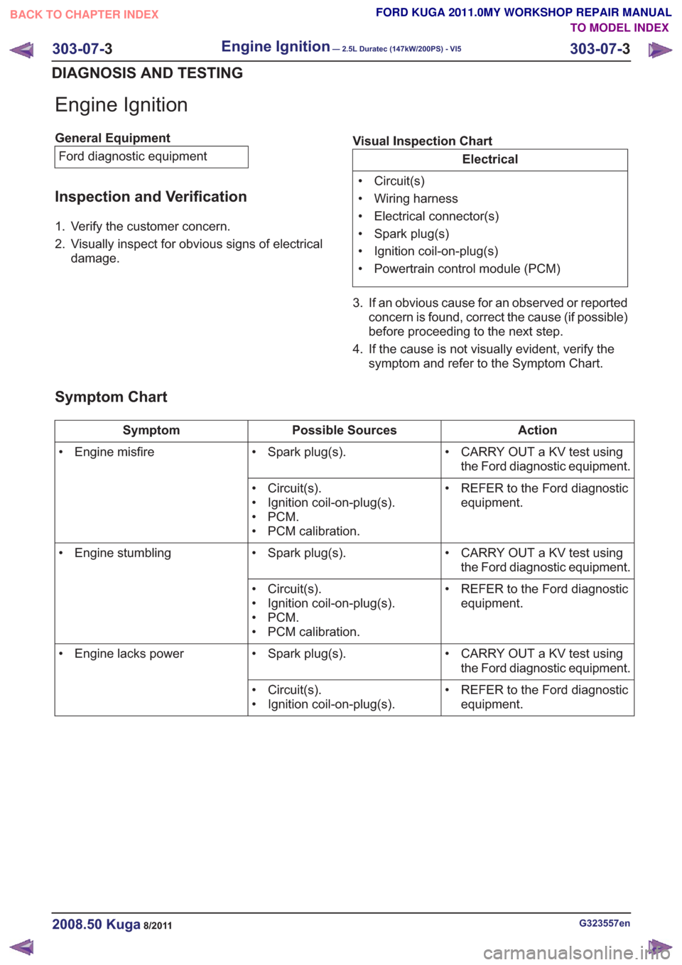
Engine Ignition
General EquipmentFord diagnostic equipment
Inspection and Verification
1. Verify the customer concern.
2. Visually inspect for obvious signs of electrical damage. Visual Inspection Chart
Electrical
• Circuit(s)
• Wiring harness
• Electrical connector(s)
• Spark plug(s)
• Ignition coil-on-plug(s)
• Powertrain control module (PCM)
3. If an obvious cause for an observed or reported concern is found, correct the cause (if possible)
before proceeding to the next step.
4. If the cause is not visually evident, verify the symptom and refer to the Symptom Chart.
Symptom Chart
Action
Possible Sources
Symptom
• CARRY OUT a KV test usingthe Ford diagnostic equipment.
• Spark plug(s).
• Engine misfire
• REFER to the Ford diagnosticequipment.
• Circuit(s).
• Ignition coil-on-plug(s).
•PCM.
• PCM calibration.
• CARRY OUT a KV test usingthe Ford diagnostic equipment.
• Spark plug(s).
• Engine stumbling
• REFER to the Ford diagnosticequipment.
• Circuit(s).
• Ignition coil-on-plug(s).
•PCM.
• PCM calibration.
• CARRY OUT a KV test usingthe Ford diagnostic equipment.
• Spark plug(s).
• Engine lacks power
• REFER to the Ford diagnosticequipment.
• Circuit(s).
• Ignition coil-on-plug(s).
G323557en2008.50 Kuga8/2011
303-07-
3
Engine Ignition— 2.5L Duratec (147kW/200PS) - VI5303-07-
3
DIAGNOSIS AND TESTING
TO MODEL INDEX
BACK TO CHAPTER INDEX
FORD KUGA 2011.0MY WORKSHOP REPAIR MANUAL
Page 1763 of 2057
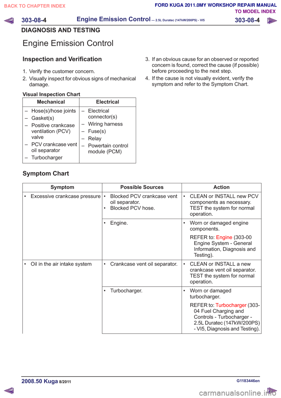
Engine Emission Control
Inspection and Verification
1. Verify the customer concern.
2. Visually inspect for obvious signs of mechanicaldamage.
Visual Inspection Chart
Electrical
Mechanical
– Electricalconnector(s)
– Wiring harness
– Fuse(s)
– Relay
– Powertain control module (PCM)
– Hose(s)/hose joints
– Gasket(s)
– Positive crankcase
ventilation (PCV)
valve
– PCV crankcase vent oil separator
– Turbocharger 3. If an obvious cause for an observed or reported
concern is found, correct the cause (if possible)
before proceeding to the next step.
4. If the cause is not visually evident, verify the symptom and refer to the Symptom Chart.
Symptom Chart
Action
Possible Sources
Symptom
• CLEAN or INSTALL new PCVcomponents as necessary.
TEST the system for normal
operation.
• Blocked PCV crankcase vent
oil separator.
• Blocked PCV hose.
• Excessive crankcase pressure
• Worn or damaged enginecomponents.
REFER to: Engine(303-00
Engine System - General
Information, Diagnosis and
Testing).
• Engine.
• CLEAN or INSTALL a newcrankcase vent oil separator.
TEST the system for normal
operation.
• Crankcase vent oil separator.
• Oil in the air intake system
• Worn or damagedturbocharger.
REFER to: Turbocharger (303-
04 Fuel Charging and
Controls - Turbocharger -
2.5L Duratec (147kW/200PS)
- VI5, Diagnosis and Testing).
• Turbocharger.
G1183446en2008.50 Kuga8/2011
303-08-
4
Engine Emission Control— 2.5L Duratec (147kW/200PS) - VI5303-08-
4
DIAGNOSIS AND TESTING
TO MODEL INDEX
BACK TO CHAPTER INDEX
FORD KUGA 2011.0MY WORKSHOP REPAIR MANUAL
Page 1768 of 2057
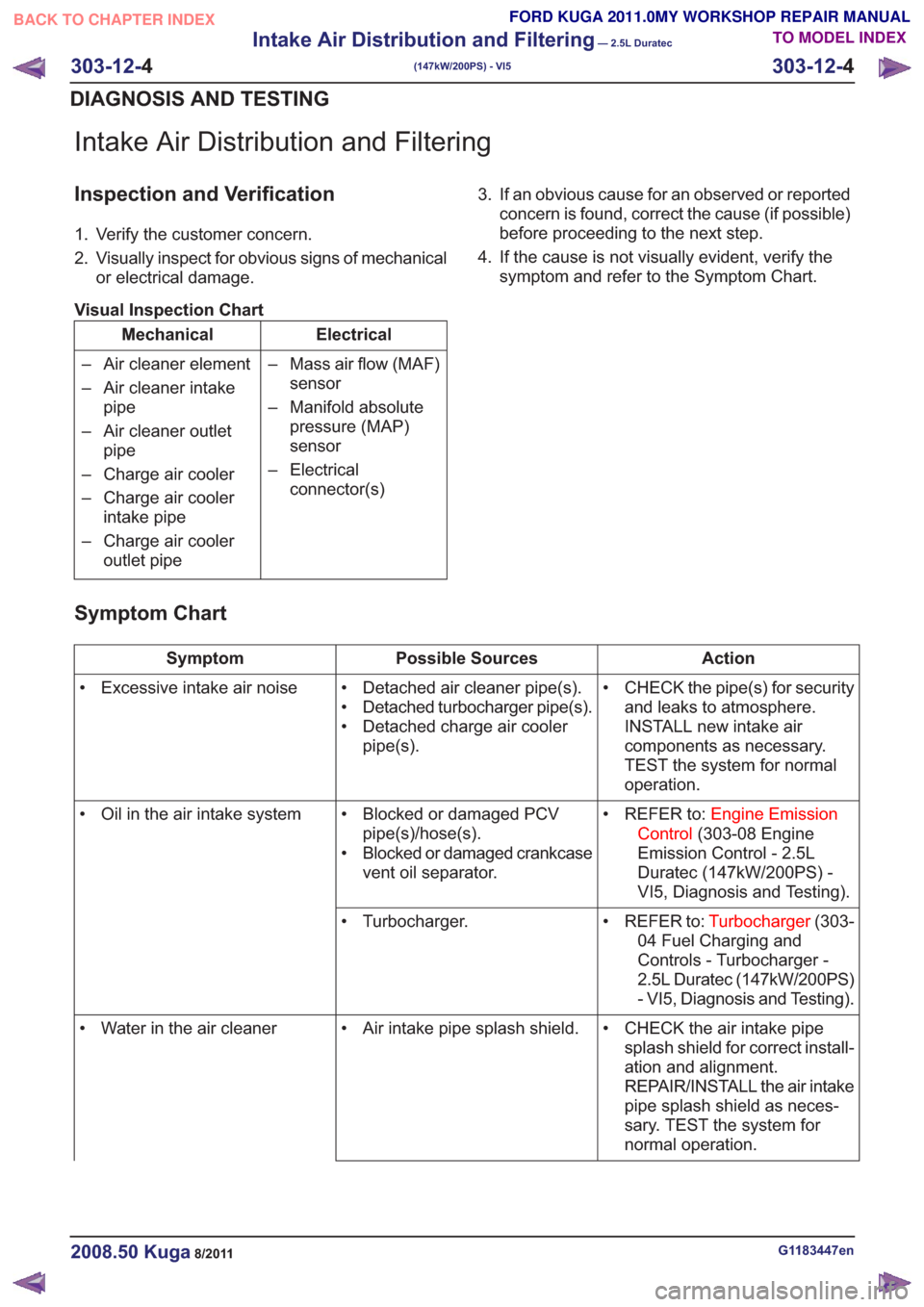
Intake Air Distribution and Filtering
Inspection and Verification
1. Verify the customer concern.
2. Visually inspect for obvious signs of mechanicalor electrical damage.
Visual Inspection Chart
Electrical
Mechanical
– Mass air flow (MAF)sensor
– Manifold absolute pressure (MAP)
sensor
– Electrical connector(s)
– Air cleaner element
– Air cleaner intake
pipe
– Air cleaner outlet pipe
– Charge air cooler
– Charge air cooler intake pipe
– Charge air cooler outlet pipe 3. If an obvious cause for an observed or reported
concern is found, correct the cause (if possible)
before proceeding to the next step.
4. If the cause is not visually evident, verify the symptom and refer to the Symptom Chart.
Symptom Chart
Action
Possible Sources
Symptom
• CHECK the pipe(s) for securityand leaks to atmosphere.
INSTALL new intake air
components as necessary.
TEST the system for normal
operation.
• Detached air cleaner pipe(s).
• Detached turbocharger pipe(s).
• Detached charge air cooler
pipe(s).
• Excessive intake air noise
• REFER to:Engine Emission
Control (303-08 Engine
Emission Control - 2.5L
Duratec (147kW/200PS) -
VI5, Diagnosis and Testing).
• Blocked or damaged PCV
pipe(s)/hose(s).
• Blocked or damaged crankcase vent oil separator.
• Oil in the air intake system
• REFER to:Turbocharger(303-
04 Fuel Charging and
Controls - Turbocharger -
2.5L Duratec (147kW/200PS)
- VI5, Diagnosis and Testing).
• Turbocharger.
• CHECK the air intake pipesplash shield for correct install-
ation and alignment.
REPAIR/INSTALL the air intake
pipe splash shield as neces-
sary. TEST the system for
normal operation.
• Air intake pipe splash shield.
• Water in the air cleaner
G1183447en2008.50 Kuga8/2011
303-12- 4
Intake Air Distribution and Filtering
— 2.5L Duratec
(147kW/200PS) - VI5
303-12- 4
DIAGNOSIS AND TESTING
TO MODEL INDEX
BACK TO CHAPTER INDEX
FORD KUGA 2011.0MY WORKSHOP REPAIR MANUAL
Page 1774 of 2057
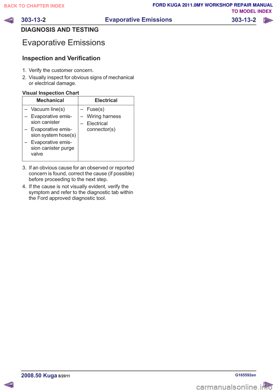
Evaporative Emissions
Inspection and Verification
1. Verify the customer concern.
2. Visually inspect for obvious signs of mechanicalor electrical damage.
Visual Inspection Chart
Electrical
Mechanical
– Fuse(s)
– Wiring harness
– Electricalconnector(s)
– Vacuum line(s)
– Evaporative emis-
sion canister
– Evaporative emis- sion system hose(s)
– Evaporative emis- sion canister purge
valve
3. If an obvious cause for an observed or reported concern is found, correct the cause (if possible)
before proceeding to the next step.
4. If the cause is not visually evident, verify the symptom and refer to the diagnostic tab within
the Ford approved diagnostic tool.
G165592en2008.50 Kuga8/2011
303-13- 2
Evaporative Emissions
303-13- 2
DIAGNOSIS AND TESTING
TO MODEL INDEX
BACK TO CHAPTER INDEX
FORD KUGA 2011.0MY WORKSHOP REPAIR MANUAL
Page 1781 of 2057
Electronic Engine Controls – Overview
General overview
Engine Management System
• Bosch ME 9.0 engine management system
• Knock control with two knock sensors
• Electronic Throttle Control Unit.
• Electronic accelerator pedal
• Variable camshaft timing for intake and exhaustcamshafts • Fuel injection supply manifold with combined
fuel pressure and temperature sensor
• Sequential multi-port fuel injection
• Camshaft position (CMP) sensors for intake and exhaust camshafts.
• satisfies the European exhaust emissions standard IV
• EOBD (European On-board Diagnostic) for the monitoring of emissions-related components.
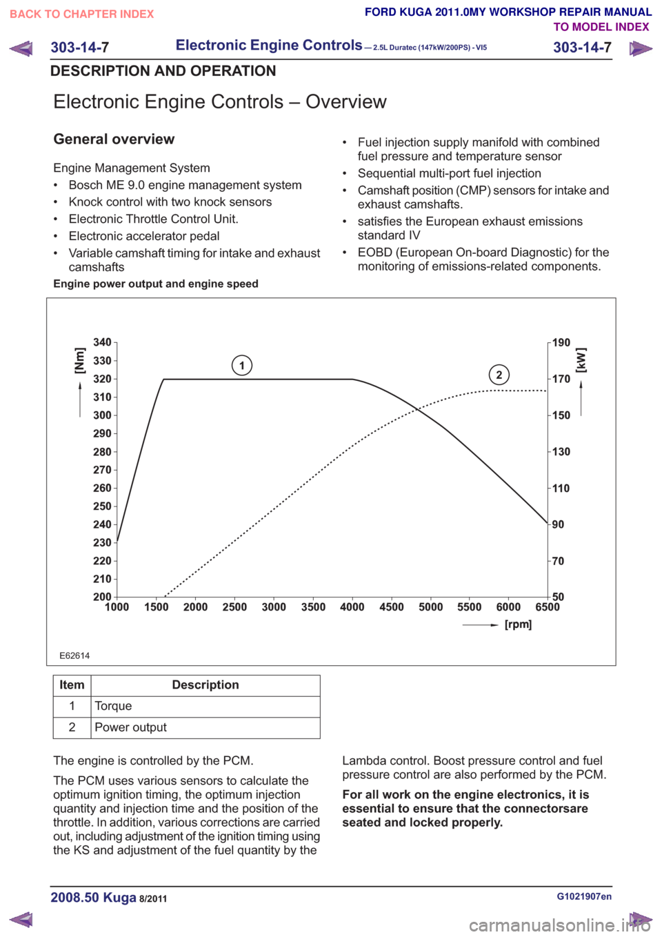
Engine power output and engine speed
2
E62614
1
Description
Item
Torque
1
Power output
2
The engine is controlled by the PCM.
The PCM uses various sensors to calculate the
optimum ignition timing, the optimum injection
quantity and injection time and the position of the
throttle. In addition, various corrections are carried
out, including adjustment of the ignition timing using
the KS and adjustment of the fuel quantity by the Lambda control. Boost pressure control and fuel
pressure control are also performed by the PCM.
For all work on the engine electronics, it is
essential to ensure that the connectorsare
seated and locked properly.
G1021907en2008.50 Kuga8/2011
303-14-
7
Electronic Engine Controls— 2.5L Duratec (147kW/200PS) - VI5303-14-
7
DESCRIPTION AND OPERATION
TO MODEL INDEX
BACK TO CHAPTER INDEX
FORD KUGA 2011.0MY WORKSHOP REPAIR MANUAL
Page 1782 of 2057
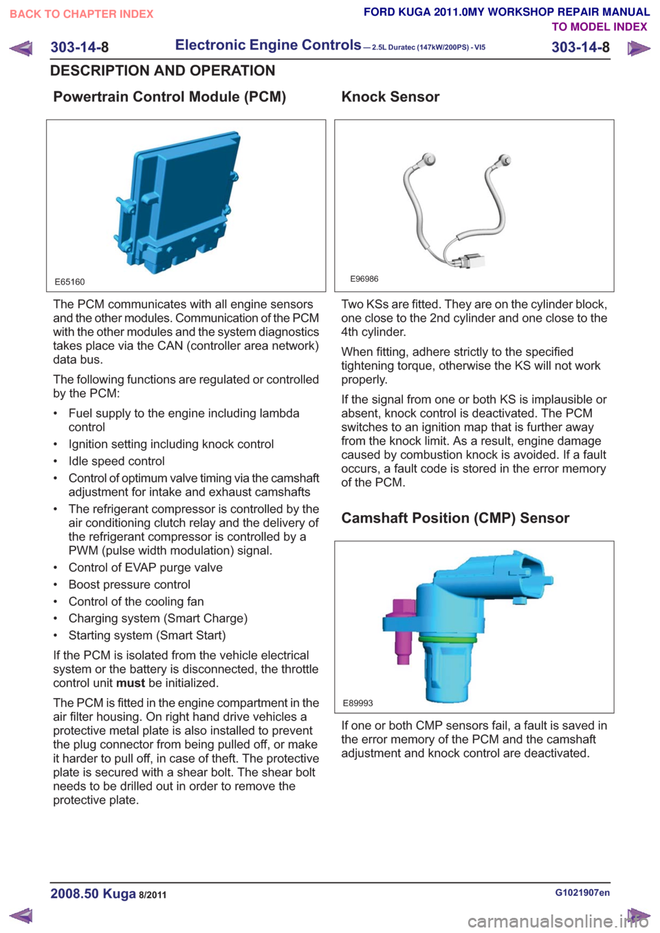
Powertrain Control Module (PCM)
E65160
The PCM communicates with all engine sensors
and the other modules. Communication of the PCM
with the other modules and the system diagnostics
takes place via the CAN (controller area network)
data bus.
The following functions are regulated or controlled
by the PCM:
• Fuel supply to the engine including lambdacontrol
• Ignition setting including knock control
• Idle speed control
• Control of optimum valve timing via the camshaft adjustment for intake and exhaust camshafts
• The refrigerant compressor is controlled by the air conditioning clutch relay and the delivery of
the refrigerant compressor is controlled by a
PWM (pulse width modulation) signal.
• Control of EVAP purge valve
• Boost pressure control
• Control of the cooling fan
• Charging system (Smart Charge)
• Starting system (Smart Start)
If the PCM is isolated from the vehicle electrical
system or the battery is disconnected, the throttle
control unit mustbe initialized.
The PCM is fitted in the engine compartment in the
air filter housing. On right hand drive vehicles a
protective metal plate is also installed to prevent
the plug connector from being pulled off, or make
it harder to pull off, in case of theft. The protective
plate is secured with a shear bolt. The shear bolt
needs to be drilled out in order to remove the
protective plate.
Knock Sensor
E96986
Two KSs are fitted. They are on the cylinder block,
one close to the 2nd cylinder and one close to the
4th cylinder.
When fitting, adhere strictly to the specified
tightening torque, otherwise the KS will not work
properly.
If the signal from one or both KS is implausible or
absent, knock control is deactivated. The PCM
switches to an ignition map that is further away
from the knock limit. As a result, engine damage
caused by combustion knock is avoided. If a fault
occurs, a fault code is stored in the error memory
of the PCM.
Camshaft Position (CMP) Sensor
E89993
If one or both CMP sensors fail, a fault is saved in
the error memory of the PCM and the camshaft
adjustment and knock control are deactivated.
G1021907en2008.50 Kuga8/2011
303-14- 8
Electronic Engine Controls— 2.5L Duratec (147kW/200PS) - VI5303-14-
8
DESCRIPTION AND OPERATION
TO MODEL INDEX
BACK TO CHAPTER INDEX
FORD KUGA 2011.0MY WORKSHOP REPAIR MANUAL
Page 1788 of 2057
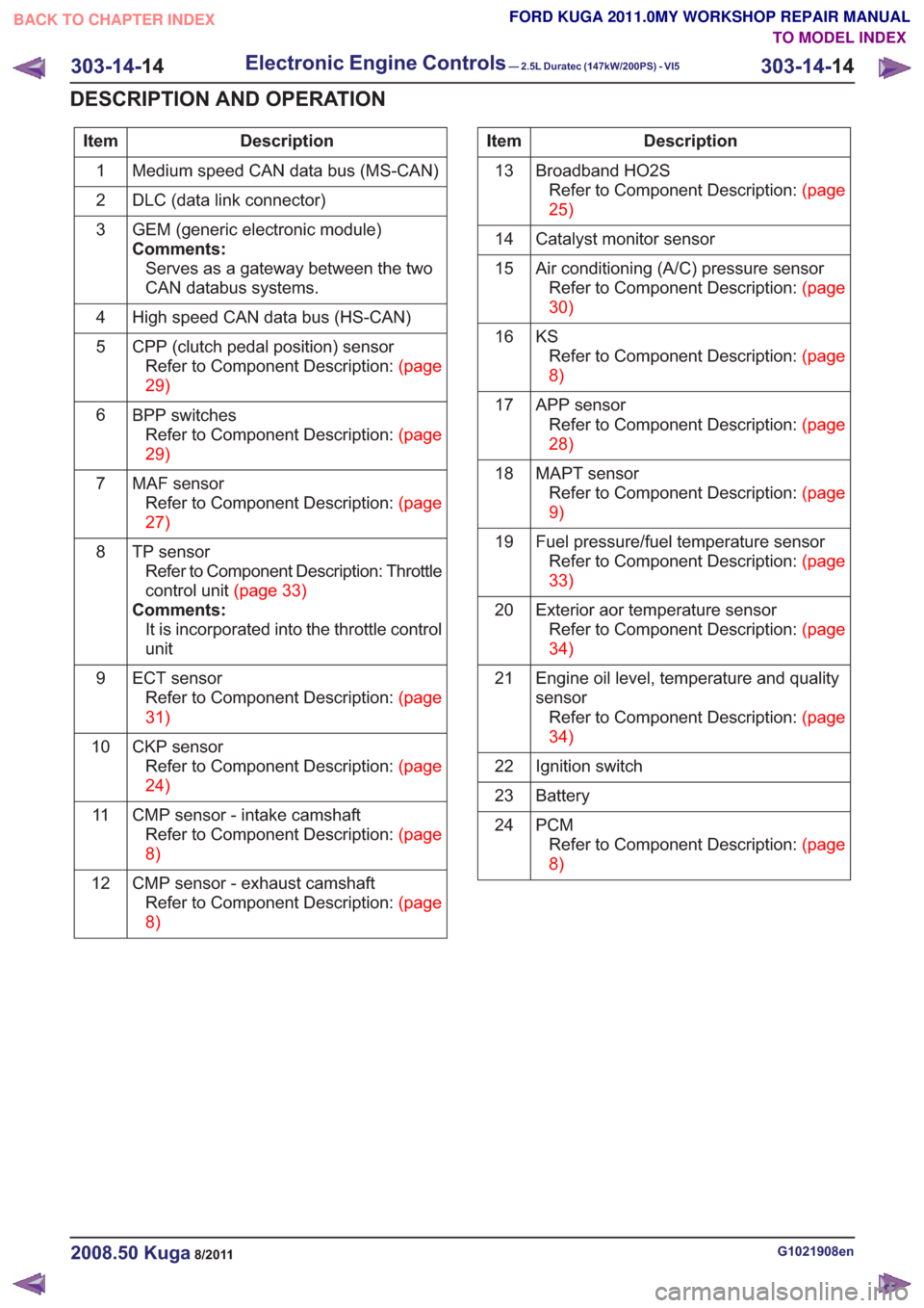
Description
Item
Medium speed CAN data bus (MS-CAN)
1
DLC (data link connector)
2
GEM (generic electronic module)
Comments:Serves as a gateway between the two
CAN databus systems.
3
High speed CAN data bus (HS-CAN)
4
CPP (clutch pedal position) sensorRefertoComponentDescription:(page
29)
5
BPP switchesRefertoComponentDescription:(page
29)
6
MAF sensorRefertoComponentDescription:(page
27)
7
TP sensorRefer to Component Description: Throttle
controlunit(page33)
Comments: It is incorporated into the throttle control
unit
8
ECT sensorRefertoComponentDescription:(page
31)
9
CKP sensorRefertoComponentDescription:(page
24)
10
CMP sensor - intake camshaftRefertoComponentDescription:(page
8)
11
CMP sensor - exhaust camshaftRefertoComponentDescription:(page
8)
12Description
Item
Broadband HO2SRefertoComponentDescription:(page
25)
13
Catalyst monitor sensor
14
Air conditioning (A/C) pressure sensorRefertoComponentDescription:(page
30)
15
KSRefertoComponentDescription:(page
8)
16
APP sensorRefertoComponentDescription:(page
28)
17
MAPT sensorRefertoComponentDescription:(page
9)
18
Fuel pressure/fuel temperature sensorRefertoComponentDescription:(page
33)
19
Exterior aor temperature sensorRefertoComponentDescription:(page
34)
20
Engine oil level, temperature and quality
sensorRefertoComponentDescription:(page
34)
21
Ignition switch
22
Battery
23
PCMRefertoComponentDescription:(page
8)
24
G1021908en2008.50 Kuga8/2011
303-14-
14
Electronic Engine Controls— 2.5L Duratec (147kW/200PS) - VI5303-14-
14
DESCRIPTION AND OPERATION
TO MODEL INDEX
BACK TO CHAPTER INDEX
FORD KUGA 2011.0MY WORKSHOP REPAIR MANUAL