Page 1528 of 2057
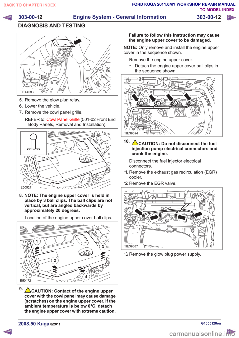
TIE44583
5. Remove the glow plug relay.
6. Lower the vehicle.
7. Remove the cowl panel grille.REFER to: Cowl Panel Grille (501-02 Front End
Body Panels, Removal and Installation).
E50527
8. NOTE: The engine upper cover is held in place by 3 ball clips. The ball clips are not
vertical, but are angled backwards by
approximately 20 degrees.
Location of the engine upper cover ball clips.
E50472
2
1
3
4
9.CAUTION: Contact of the engine upper
cover with the cowl panel may cause damage
(scratches) on the engine upper cover. If the
ambient temperature is below 0°C, detach
the engine upper cover with extreme caution. Failure to follow this instruction may cause
the engine upper cover to be damaged.
NOTE: Only remove and install the engine upper
cover in the sequence shown.
Remove the engine upper cover.• Detach the engine upper cover ball clips in the sequence shown.
TIE39594
10.CAUTION: Do not disconnect the fuel
injection pump electrical connectors and
crank the engine.
Disconnect the fuel injector electrical
connectors.
11. Remove the exhaust gas recirculation (EGR) cooler.
12. Remove the EGR valve.
TIE39687
13. Remove the glow plug power supply.
G1055128en2008.50 Kuga8/2011
303-00- 12
Engine System - General Information
303-00- 12
DIAGNOSIS AND TESTING
TO MODEL INDEX
BACK TO CHAPTER INDEX
FORD KUGA 2011.0MY WORKSHOP REPAIR MANUAL
Page 1529 of 2057
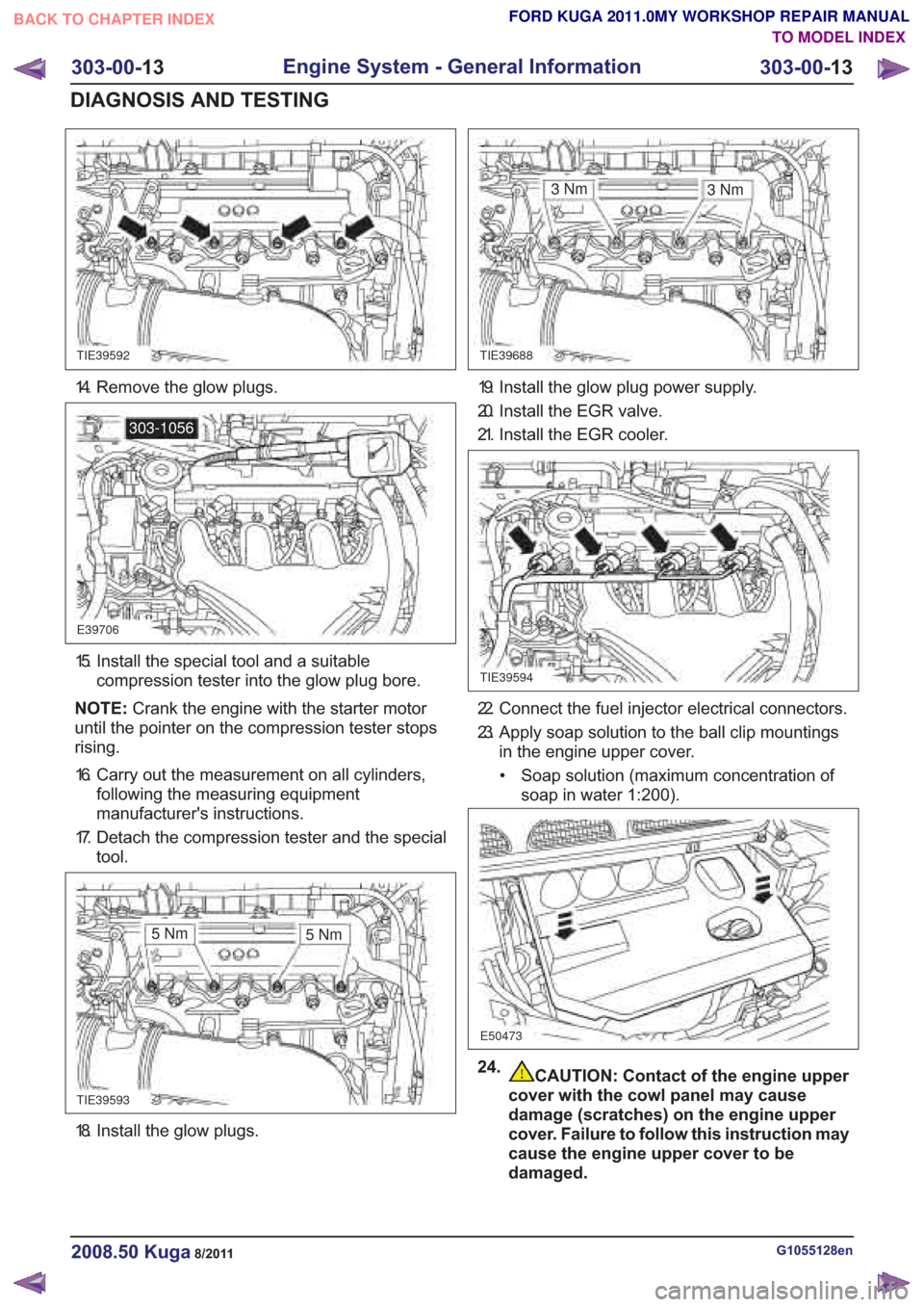
18. Install the glow plugs.
CAUTION: Contact of the engine upper
cover with the cowl panel may cause
damage (scratches) on the engine upper
cover. Failure to follow this instruction may
cause the engine upper cover to be
damaged.
G1055128en2008.50 Kuga8/2011
303-00- 13
Engine System - General Information
303-00- 13
DIAGNOSIS AND TESTING
FORD KUGA 2011.0MY WORKSHOP REPAIR MANUAL
TO MODEL INDEX
BACK TO CHAPTER INDEX
TIE39592TIE39688
E39706
303-1056
TIE39593
3Nm
TIE39594
E50473
3Nm
5Nm 5Nm
14. Remove the glow plugs.
15. Install the special tool and a suitable
compression tester into the glow plug bore.
NOTE: Crank the engine with the starter motor
until the pointer on the compression tester stops
rising.
16. Carry out the measurement on all cylinders, following the measuring equipment
manufacturer's instructions.
17. Detach the compression tester and the special tool.
19. Install the glow plug power supply.
20. Install the EGR valve.
21. Install the EGR cooler.
22. Connect the fuel injector electrical connectors.
23. Apply soap solution to the ball clip mountingsin the engine upper cover.
• Soap solution (maximum concentration of soap in water 1:200).
24.
Page 1530 of 2057
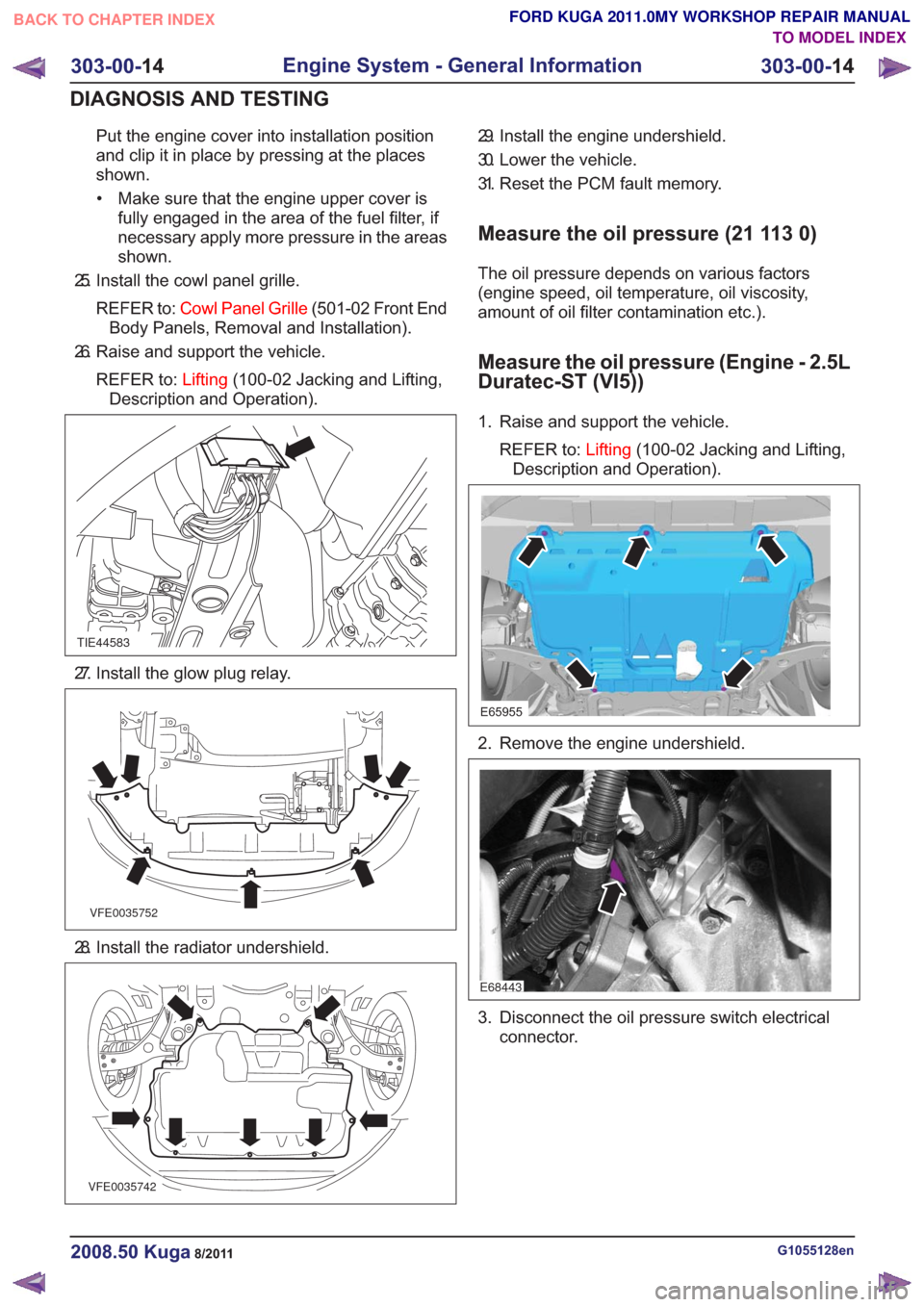
Put the engine cover into installation position
and clip it in place by pressing at the places
shown.• Make sure that the engine upper cover is fully engaged in the area of the fuel filter, if
necessary apply more pressure in the areas
shown.
25. Install the cowl panel grille.
REFER to: Cowl Panel Grille (501-02 Front End
Body Panels, Removal and Installation).
26. Raise and support the vehicle.
REFER to: Lifting(100-02 Jacking and Lifting,
Description and Operation).
TIE44583
27. Install the glow plug relay.
VFE0035752
28. Install the radiator undershield.
VFE0035742
29. Install the engine undershield.
30. Lower the vehicle.
31. Reset the PCM fault memory.
Measure the oil pressure (21 113 0)
The oil pressure depends on various factors
(engine speed, oil temperature, oil viscosity,
amount of oil filter contamination etc.).
Measure the oil pressure (Engine - 2.5L
Duratec-ST (VI5))
1. Raise and support the vehicle.
REFER to: Lifting(100-02 Jacking and Lifting,
Description and Operation).
E65955
2. Remove the engine undershield.
E68443
3. Disconnect the oil pressure switch electrical connector.
G1055128en2008.50 Kuga8/2011
303-00- 14
Engine System - General Information
303-00- 14
DIAGNOSIS AND TESTING
TO MODEL INDEX
BACK TO CHAPTER INDEX
FORD KUGA 2011.0MY WORKSHOP REPAIR MANUAL
Page 1531 of 2057
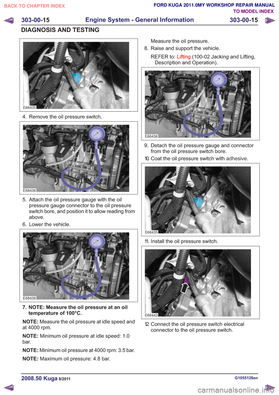
E68435
4. Remove the oil pressure switch.
E68436
5. Attach the oil pressure gauge with the oilpressure gauge connector to the oil pressure
switch bore, and position it to allow reading from
above.
6. Lower the vehicle.
E68436
7. NOTE: Measure the oil pressure at an oil temperature of 100°C.
NOTE: Measure the oil pressure at idle speed and
at 4000 rpm.
NOTE: Minimum oil pressure at idle speed: 1.0
bar.
NOTE: Minimum oil pressure at 4000 rpm: 3.5 bar.
NOTE: Maximum oil pressure: 4.8 bar. Measure the oil pressure.
8. Raise and support the vehicle.
REFER to: Lifting(100-02 Jacking and Lifting,
Description and Operation).
E68436
9. Detach the oil pressure gauge and connector from the oil pressure switch bore.
10. Coat the oil pressure switch with adhesive.
E68435
11. Install the oil pressure switch.
E68443
12. Connect the oil pressure switch electrical
connector to the oil pressure switch.
G1055128en2008.50 Kuga8/2011
303-00- 15
Engine System - General Information
303-00- 15
DIAGNOSIS AND TESTING
TO MODEL INDEX
BACK TO CHAPTER INDEX
FORD KUGA 2011.0MY WORKSHOP REPAIR MANUAL
Page 1532 of 2057
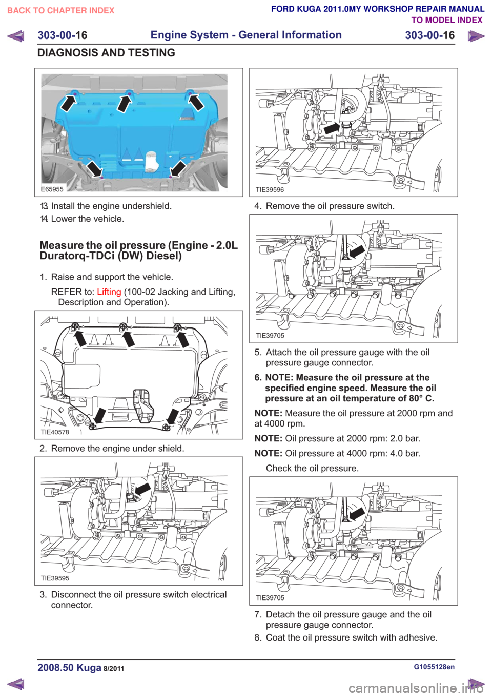
E65955
13. Install the engine undershield.
14. Lower the vehicle.
Measure the oil pressure (Engine - 2.0L
Duratorq-TDCi (DW) Diesel)
1. Raise and support the vehicle.REFER to: Lifting(100-02 Jacking and Lifting,
Description and Operation).
TIE40578
2. Remove the engine under shield.
TIE39595
3. Disconnect the oil pressure switch electrical connector.
TIE39596
4. Remove the oil pressure switch.
TIE39705
5. Attach the oil pressure gauge with the oilpressure gauge connector.
6. NOTE: Measure the oil pressure at the specified engine speed. Measure the oil
pressure at an oil temperature of 80° C.
NOTE: Measure the oil pressure at 2000 rpm and
at 4000 rpm.
NOTE: Oil pressure at 2000 rpm: 2.0 bar.
NOTE: Oil pressure at 4000 rpm: 4.0 bar.
Check the oil pressure.
TIE39705
7. Detach the oil pressure gauge and the oil pressure gauge connector.
8. Coat the oil pressure switch with adhesive.
G1055128en2008.50 Kuga8/2011
303-00-16
Engine System - General Information
303-00- 16
DIAGNOSIS AND TESTING
TO MODEL INDEX
BACK TO CHAPTER INDEX
FORD KUGA 2011.0MY WORKSHOP REPAIR MANUAL
Page 1533 of 2057
TIE39704
35 Nm
9. Install the oil pressure switch.
TIE39595
10. Connect the oil pressure switch electricalconnector.
VFE0035742
11. Install the engine under shield.
12. Lower the vehicle.
Valve train analysis - static (engine off)
Remove the valve cover.
Check all valve train components for damage and
wear. Make sure that only original components are
installed and that all bolts and nuts have been
tightened to the correct tightening torque.
G1055128en2008.50 Kuga8/2011
303-00- 17
Engine System - General Information
303-00- 17
DIAGNOSIS AND TESTING
TO MODEL INDEX
BACK TO CHAPTER INDEX
FORD KUGA 2011.0MY WORKSHOP REPAIR MANUAL
Page 1675 of 2057
Engine Cooling
Special Tool(s) / General EquipmentPressure Tester, Cooling
System
303-396 (24-001 A)
IA24001A
Adaptor for 303-396
303-396-09
E55030
Ford approved diagnostic tool
Inspection and Verification
1. Verify the customer concern.
2. Visually inspect for obvious signs of mechanicalor electrical damage.
Visual Inspection Chart
Electrical
Mechanical
– Fuse(s)
– Wiring harness
– Electricalconnector(s)
– Engine coolant temperature (ECT)
sensor
– Cooling fan motor
– Cooling fan module
– Powertrain control module (PCM)
– Coolant shut off valve
– Coolant degas shut off valve
– Coolant leaks
– Gaskets/seals
– Core plug(s)
– Hose(s)/hose joints
– Coolant expansion
tank cap and seal(s)
– Coolant expansion tank
– Radiator
– Coolant pump
– Thermostat
– Heater core
– Exhaust gas recircu- lation (EGR) cooler
3. If an obvious cause for an observed or reported concern is found, correct the cause (if possible)
before proceeding to the next step.
4. If the cause is not visually evident, verify the symptom and refer to the diagnostic tab within
the Ford approved diagnostic tool.
G1058974en2008.50 Kuga8/2011
303-03- 4
Engine Cooling
303-03- 4
DIAGNOSIS AND TESTING
TO MODEL INDEX
BACK TO CHAPTER INDEX
FORD KUGA 2011.0MY WORKSHOP REPAIR MANUAL
Page 1695 of 2057
Fuel Charging and Controls
General EquipmentFord diagnostic equipment
Inspection and Verification
1. Verify the customer concern by operating the system.
2. Visually inspect for obvious signs of mechanical or electrical damage. Visual Inspection Chart
Electrical
Mechanical
– Loose or corrodedconnector(s)
– Wiring harness
– Fuel injector(s)
– Fuel leaks
– Blocked or contamin-
ated fuel filter
– Damaged fuel supply manifold
– Damaged fuel line connections
– Damaged vacuum hoses
– Fuel rail pressure sensor
3. If an obvious cause for an observed or reported concern is found, correct the cause (if possible)
before proceeding to the next step.
4. If the concern is not visually evident, verify the symptom and refer to the Ford diagnostic
equipment .
Symptom Chart
Action
Possible Sources
Symptom
• CHECK the PATS LED extin-guishes within 3 seconds when
the ignition is turned on.
REFER to: Anti-Theft - Passive
(419-01 Anti-Theft - Passive,
Diagnosis and Testing).
• PAT S .
• Engine does not crank
• REFER to:Starting System
(303-06 Starting System -
2.5L Duratec (147kW/200PS)
- VI5, Diagnosis and Testing).
• Starting system.
• REFER to the Wiring Diagrams.
• Ignition switch.
• Carry out a full enginediagnosis using the guided
diagnostic menu in the Ford
diagnostic equipment.
• Powertrain control module
(PCM).
• RESET the IFS switch.
• Inertia fuel shutoff (IFS) switch.
• Engine cranks but does not
start
• Check the fuel system pres-sure.
• Low fuel system pressure.
G1183441en2008.50 Kuga8/2011
303-04A-
4
Fuel Charging and Controls
— 2.5L Duratec (147kW/200PS) -
VI5
303-04A- 4
DIAGNOSIS AND TESTING
TO MODEL INDEX
BACK TO CHAPTER INDEX
FORD KUGA 2011.0MY WORKSHOP REPAIR MANUAL