Page 1798 of 2057

Starting process
The PCM enables the starting process when a key
providing a valid code is read via the PATS.
Refer to:Starting System (303-06 Starting System
- 2.5L Duratec (147kW/200PS) - VI5, Description
and Operation).
Alternator control (Smart Charge)
The vehicle is fitted with a Smart Charging charge
system.
In this system, the charge voltage is regulated by
the PCM.
Refer to: Generator (414-02 Generator and
Regulator, Description and Operation).
Component Description
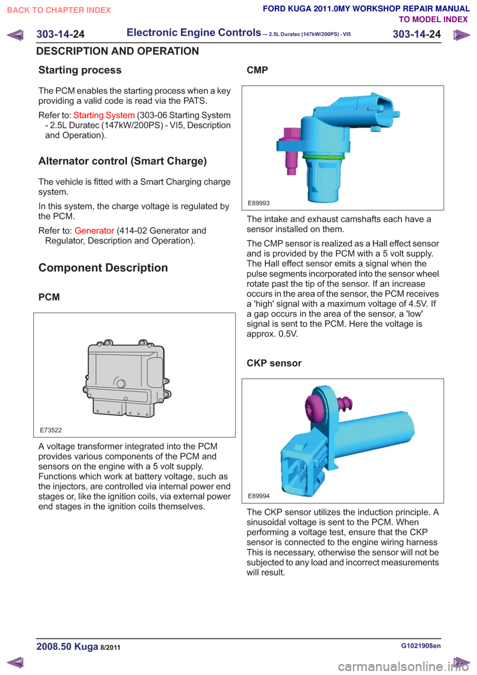
PCM
E73522
A voltage transformer integrated into the PCM
provides various components of the PCM and
sensors on the engine with a 5 volt supply.
Functions which work at battery voltage, such as
the injectors, are controlled via internal power end
stages or, like the ignition coils, via external power
end stages in the ignition coils themselves.
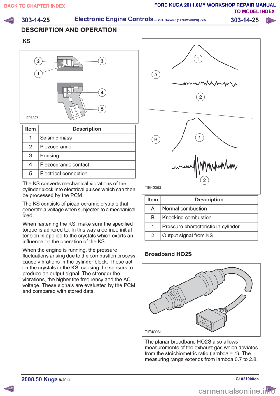
CMP
E89993
The intake and exhaust camshafts each have a
sensor installed on them.
The CMP sensor is realized as a Hall effect sensor
and is provided by the PCM with a 5 volt supply.
The Hall effect sensor emits a signal when the
pulse segments incorporated into the sensor wheel
rotate past the tip of the sensor. If an increase
occurs in the area of the sensor, the PCM receives
a 'high' signal with a maximum voltage of 4.5V. If
a gap occurs in the area of the sensor, a 'low'
signal is sent to the PCM. Here the voltage is
approx. 0.5V.
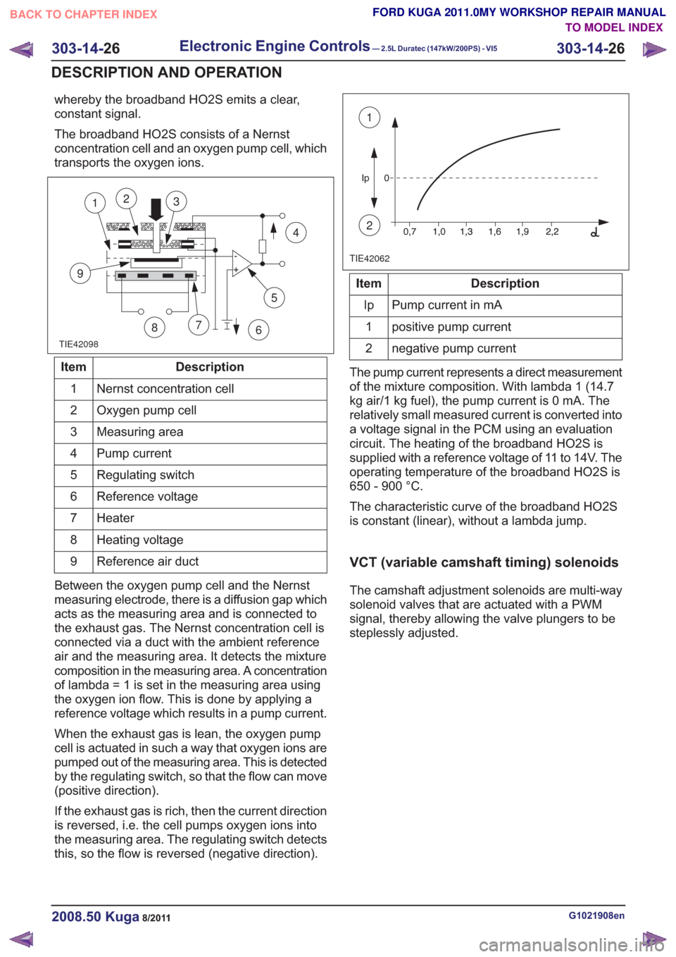
CKP sensor
E89994
The CKP sensor utilizes the induction principle. A
sinusoidal voltage is sent to the PCM. When
performing a voltage test, ensure that the CKP
sensor is connected to the engine wiring harness
This is necessary, otherwise the sensor will not be
subjected to any load and incorrect measurements
will result.
G1021908en2008.50 Kuga8/2011
303-14- 24
Electronic Engine Controls— 2.5L Duratec (147kW/200PS) - VI5303-14-
24
DESCRIPTION AND OPERATION
TO MODEL INDEX
BACK TO CHAPTER INDEX
FORD KUGA 2011.0MY WORKSHOP REPAIR MANUAL
Page 1799 of 2057

KS
E96327
23
5
4
1
Description
Item
Seismic mass
1
Piezoceramic
2
Housing
3
Piezoceramic contact
4
Electrical connection
5
The KS converts mechanical vibrations of the
cylinder block into electrical pulses which can then
be processed by the PCM.
The KS consists of piezo-ceramic crystals that
generate a voltage when subjected to a mechanical
load.
When fastening the KS, make sure the specified
torque is adhered to. In this way a defined initial
tension is applied to the crystals which exerts an
influence on the operation of the KS.
When the engine is running, the pressure
fluctuations arising due to the combustion process
cause vibrations in the cylinder block. These act
on the crystals in the KS, causing the sensors to
produce an output signal. The stronger the
vibrations, the higher the frequency and the AC
voltage. These signals are evaluated by the PCM
and compared with stored data.
TIE42093
1
2
A
B1
2
Description
Item
Normal combustion
A
Knocking combustion
B
Pressure characteristic in cylinder
1
Output signal from KS
2
Broadband HO2S
TIE42061
The planar broadband HO2S also allows
measurements of the exhaust gas which deviates
from the stoichiometric ratio (lambda = 1). The
measuring range extends from lambda 0.7 to 2.8,
G1021908en2008.50 Kuga8/2011
303-14- 25
Electronic Engine Controls— 2.5L Duratec (147kW/200PS) - VI5303-14-
25
DESCRIPTION AND OPERATION
TO MODEL INDEX
BACK TO CHAPTER INDEX
FORD KUGA 2011.0MY WORKSHOP REPAIR MANUAL
Page 1800 of 2057

whereby the broadband HO2S emits a clear,
constant signal.
The broadband HO2S consists of a Nernst
concentration cell and an oxygen pump cell, which
transports the oxygen ions.
TIE42098
5
7
9
12
86
4
3
Description
Item
Nernst concentration cell
1
Oxygen pump cell
2
Measuring area
3
Pump current
4
Regulating switch
5
Reference voltage
6
Heater
7
Heating voltage
8
Reference air duct
9
Between the oxygen pump cell and the Nernst
measuring electrode, there is a diffusion gap which
acts as the measuring area and is connected to
the exhaust gas. The Nernst concentration cell is
connected via a duct with the ambient reference
air and the measuring area. It detects the mixture
composition in the measuring area. A concentration
of lambda = 1 is set in the measuring area using
the oxygen ion flow. This is done by applying a
reference voltage which results in a pump current.
When the exhaust gas is lean, the oxygen pump
cell is actuated in such a way that oxygen ions are
pumped out of the measuring area. This is detected
by the regulating switch, so that the flow can move
(positive direction).
If the exhaust gas is rich, then the current direction
is reversed, i.e. the cell pumps oxygen ions into
the measuring area. The regulating switch detects
this, so the flow is reversed (negative direction).
TIE42062
1
2
Description
Item
Pump current in mA
Ip
positive pump current
1
negative pump current
2
The pump current represents a direct measurement
of the mixture composition. With lambda 1 (14.7
kg air/1 kg fuel), the pump current is 0 mA. The
relatively small measured current is converted into
a voltage signal in the PCM using an evaluation
circuit. The heating of the broadband HO2S is
supplied with a reference voltage of 11 to 14V. The
operating temperature of the broadband HO2S is
650 - 900 °C.
The characteristic curve of the broadband HO2S
is constant (linear), without a lambda jump.
VCT (variable camshaft timing) solenoids
The camshaft adjustment solenoids are multi-way
solenoid valves that are actuated with a PWM
signal, thereby allowing the valve plungers to be
steplessly adjusted.
G1021908en2008.50 Kuga8/2011
303-14- 26
Electronic Engine Controls— 2.5L Duratec (147kW/200PS) - VI5303-14-
26
DESCRIPTION AND OPERATION
TO MODEL INDEX
BACK TO CHAPTER INDEX
FORD KUGA 2011.0MY WORKSHOP REPAIR MANUAL
Page 1962 of 2057
SECTION 309-00 Exhaust System— 2.5L Duratec (147kW/200PS) - VI5
VEHICLE APPLICATION:2008.50 Kuga
PA G E
CONTENTS
DESCRIPTION AND OPERATION
309-00-2
Exhaust System (Component Location) ........................................................................\
.....
REMOVAL AND INSTALLATION 309-00-3
Exhaust Flexible Pipe ........................................................................\
.................................
309-00-6
Catalytic Converter ........................................................................\
.....................................
309-00-1
Exhaust System— 2.5L Duratec (147kW/200PS) - VI5309-00-
1
.
TO MODEL INDEX
BACK TO CHAPTER INDEX
FORD KUGA 2011.0MY WORKSHOP REPAIR MANUAL
Page 1963 of 2057
Exhaust System – Component Location
E106894
1
2
3
4
5
6
7
8
Description
Item
Exhaust flexible pipe gasket
1
HO2S (heated oxygen sensor)
2
Exhaust flexible pipe
3
Front gasket, catalytic converter
4Description
Item
Exhaust catalytic convertor
5
Rear gasket, catalytic converter
6
Rear Muffler
7
Catalyst monitor sensor
8
G1079149en2008.50 Kuga8/2011
309-00- 2
Exhaust System— 2.5L Duratec (147kW/200PS) - VI5309-00-
2
DESCRIPTION AND OPERATION
TO MODEL INDEX
BACK TO CHAPTER INDEX
FORD KUGA 2011.0MY WORKSHOP REPAIR MANUAL
Page 1964 of 2057
Exhaust Flexible Pipe
General EquipmentCable TiesMaterials
Specification
Name
SA-M1C9107-A / YS5J-
M1C9107-AA
Grease KS-PS
Removal
NOTE:
Removal steps in this procedure may
contain installation details.
1.
E65070
2. CAUTION: Make sure that the inside of the pipe ends are clean and free of oil
residue.
1. Torque: 10Nm
2. Torque: 4Nm
3. Torque: 10Nm
2
1
3
E68504
3.Torque: 20Nm
E112607
1
2
34
4.
E67948
2
1
5. CAUTIONS:
Jointing compound must not be used
forward of the catalytic converter.
G1079152en2008.50 Kuga8/2011
309-00- 3
Exhaust System— 2.5L Duratec (147kW/200PS) - VI5309-00-
3
REMOVAL AND INSTALLATION
TO MODEL INDEX
BACK TO CHAPTER INDEX
FORD KUGA 2011.0MY WORKSHOP REPAIR MANUAL
Page 1965 of 2057
Make sure that the exhaust flexible pipe
is not forcibly bent.
2. Torque: 47
Nm
3. Torque: 28Nm
E112609
x3
1
2
3
6. Refer to: Lifting(100-02 Jacking and Lifting,
Description and Operation).
7.
E65299
8. General Equipment: Cable Ties
TIE0014991
9.
E66050
10.Torque: 30Nm
E112254
G1079152en2008.50 Kuga8/2011
309-00- 4
Exhaust System— 2.5L Duratec (147kW/200PS) - VI5309-00-
4
REMOVAL AND INSTALLATION
TO MODEL INDEX
BACK TO CHAPTER INDEX
FORD KUGA 2011.0MY WORKSHOP REPAIR MANUAL
Page 1966 of 2057
11. CAUTION: Make sure that the exhaustflexible pipe is not forcibly bent.
Torque: 48Nm
E112253
x2
12.Material: Grease KS-PS (SA-M1C9107-A /
YS5J-M1C9107-AA) grease
Torque: 48
Nm
E112608
Installation
1. To install, reverse the removal.
G1079152en2008.50 Kuga8/2011
309-00- 5
Exhaust System— 2.5L Duratec (147kW/200PS) - VI5309-00-
5
REMOVAL AND INSTALLATION
TO MODEL INDEX
BACK TO CHAPTER INDEX
FORD KUGA 2011.0MY WORKSHOP REPAIR MANUAL