Page 1379 of 2057

Brake Pads(12 238 0)
Special Tool(s)206-012
Retractor, Rear Brake Caliper
Piston
12006
Materials
Specification
Name
WSS-M6C57-A2
Brake Fluid - Super
DOT4
Removal
NOTE: Removal steps in this procedure may
contain installation details.
1. Refer to: Brake System Health and Safety
Precautions (100-00 General Information,
Description and Operation).
2. Refer to: Wheel and Tire (204-04 Wheels and
Tires, Removal and Installation).
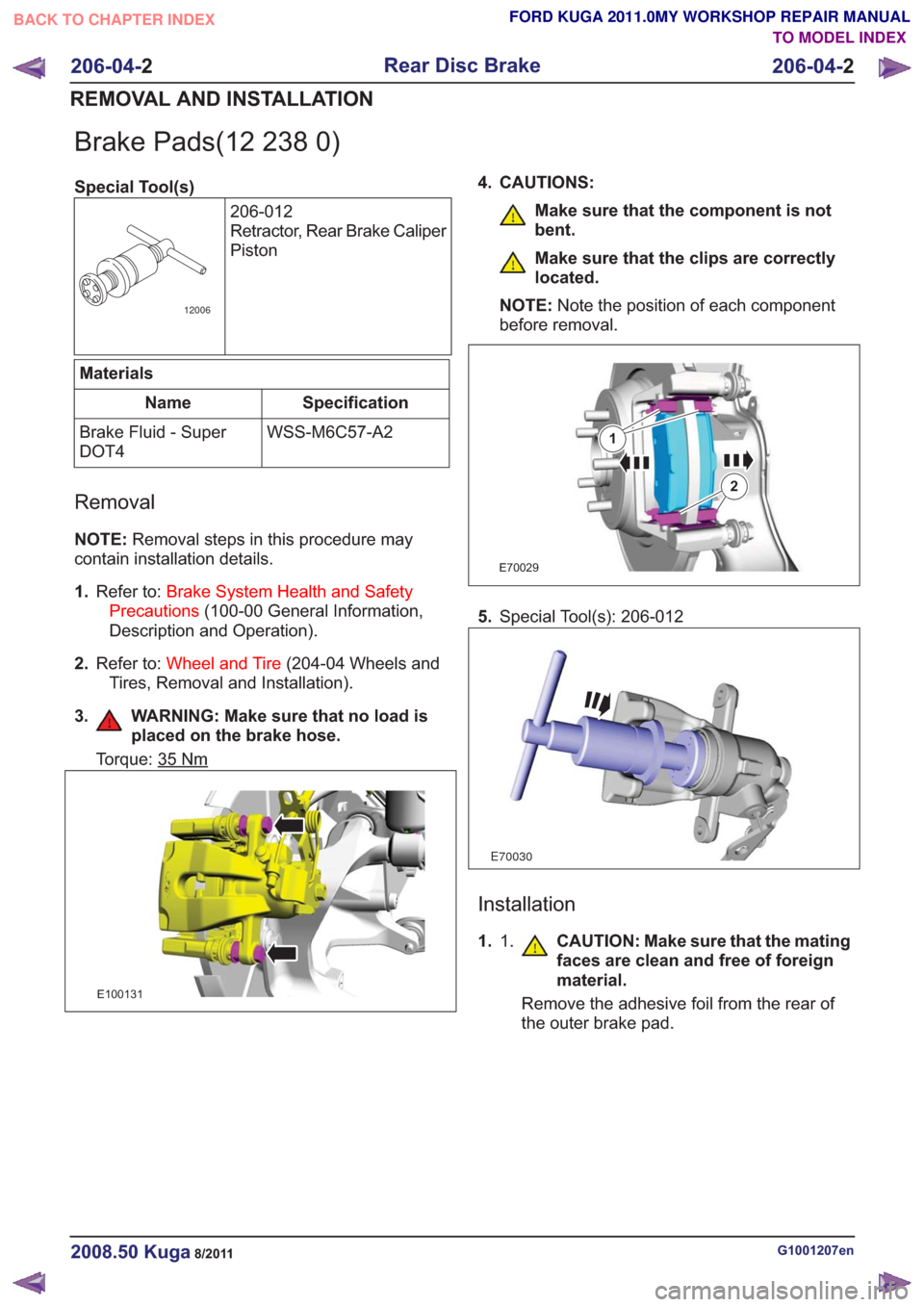
3. WARNING: Make sure that no load is placed on the brake hose.
Torque: 35Nm
E100131
4. CAUTIONS:
Make sure that the component is not
bent.
Make sure that the clips are correctly
located.
NOTE: Note the position of each component
before removal.
E70029
1
2
5. Special Tool(s): 206-012
E70030
Installation
1. 1. CAUTION: Make sure that the mating
faces are clean and free of foreign
material.
Remove the adhesive foil from the rear of
the outer brake pad.
G1001207en2008.50 Kuga8/2011
206-04- 2
Rear Disc Brake
206-04- 2
REMOVAL AND INSTALLATION
TO MODEL INDEX
BACK TO CHAPTER INDEX
FORD KUGA 2011.0MY WORKSHOP REPAIR MANUAL
Page 1381 of 2057

Brake Caliper(12 253 0)
General EquipmentHose Clamp(s)
Materials
Specification
Name
WSS-M6C57-A2
Brake Fluid - Super
DOT4
Removal
NOTE: Removal steps in this procedure may
contain installation details.
1. Refer to: Brake System Health and Safety
Precautions (100-00 General Information,
Description and Operation).
2. Refer to: Wheel and Tire (204-04 Wheels and
Tires, Removal and Installation).
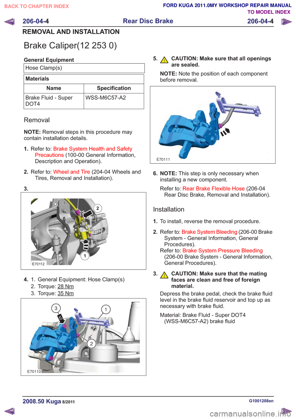
3.
E70112
1
2
4. General Equipment: Hose Clamp(s)
1.
2. Torque: 28
Nm
3. Torque: 35Nm
E70110
1
2
x2
3
5. CAUTION: Make sure that all openings
are sealed.
NOTE: Note the position of each component
before removal.
E70111
6. NOTE: This step is only necessary when
installing a new component.
Refer to: Rear Brake Flexible Hose (206-04
Rear Disc Brake, Removal and Installation).
Installation
1. To install, reverse the removal procedure.
2. Refer to: Brake System Bleeding (206-00 Brake
System - General Information, General
Procedures).
Refer to: Brake System Pressure Bleeding
(206-00 Brake System - General Information,
General Procedures).
3.
CAUTION: Make sure that the mating
faces are clean and free of foreign
material.
Depress the brake pedal, check the brake fluid
level in the brake fluid reservoir and top up as
necessary with brake fluid.
Material: Brake Fluid - Super DOT4 (WSS-M6C57-A2) brake fluid
G1001208en2008.50 Kuga8/2011
206-04- 4
Rear Disc Brake
206-04- 4
REMOVAL AND INSTALLATION
TO MODEL INDEX
BACK TO CHAPTER INDEX
FORD KUGA 2011.0MY WORKSHOP REPAIR MANUAL
Page 1382 of 2057
Rear Brake Flexible Hose
Removal
CAUTION:
Refer to:Brake System Health and Safety
Precautions (100-00 General Information,
Description and Operation).
NOTE: Removal steps in this procedure may
contain installation details. 1.
Refer to: Wheel and Tire (204-04 Wheels and
Tires, Removal and Installation).
2. WARNINGS:
Make sure that no load is placed on the
brake hose.
Be prepared to collect escaping fluid.
CAUTION: Make sure that all openings
are sealed.
1. Torque: 15
Nm
E99425
1
2
3
G1001210en2008.50 Kuga8/2011
206-04- 5
Rear Disc Brake
206-04- 5
REMOVAL AND INSTALLATION
TO MODEL INDEX
BACK TO CHAPTER INDEX
FORD KUGA 2011.0MY WORKSHOP REPAIR MANUAL
Page 1393 of 2057

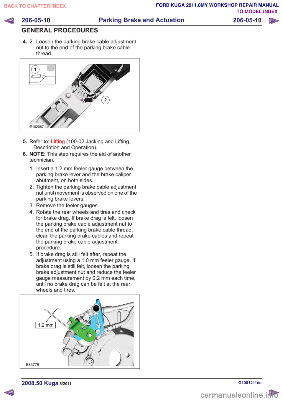
4.Loosen the parking brake cable adjustment
nut to the end of the parking brake cable
thread.
2.
E102067
2
P1
5.
Refer to: Lifting(100-02 Jacking and Lifting,
Description and Operation).
6. NOTE: This step requires the aid of another
technician.
1. Insert a 1.2 mm feeler gauge between the parking brake lever and the brake caliper
abutment, on both sides.
2. Tighten the parking brake cable adjustment nut until movement is observed on one of the
parking brake levers.
3. Remove the feeler gauges.
4. Rotate the rear wheels and tires and check for brake drag. If brake drag is felt, loosen
the parking brake cable adjustment nut to
the end of the parking brake cable thread,
clean the parking brake cables and repeat
the parking brake cable adjustment
procedure.
5. If brake drag is still felt after, repeat the adjustment using a 1.0 mm feeler gauge. If
brake drag is still felt, loosen the parking
brake adjustment nut and reduce the feeler
gauge measurement by 0.2 mm each time,
until no brake drag can be felt at the rear
wheels and tires.
E83778
1.2 mm
G1001211en2008.50 Kuga8/2011
206-05- 10
Parking Brake and Actuation
206-05- 10
GENERAL PROCEDURES
TO MODEL INDEX
BACK TO CHAPTER INDEX
FORD KUGA 2011.0MY WORKSHOP REPAIR MANUAL
Page 1395 of 2057
Parking Brake Rear Cables
Removal
NOTE:Removal steps in this procedure may
contain installation details.
1. Fully release the parking brake control.
2.
E92650
3. Loosen the parking brake cable adjustment nut
to the end of the parking brake cable thread.
E92651
4.Refer to: Wheel and Tire (204-04 Wheels and
Tires, Removal and Installation).
4x4
5. Torque: 25Nm
E101187
x2
x4
1
2
3
4x2
6.Torque: 25Nm
E101189
x4
G1072319en2008.50 Kuga8/2011
206-05- 12
Parking Brake and Actuation
206-05- 12
REMOVAL AND INSTALLATION
TO MODEL INDEX
BACK TO CHAPTER INDEX
FORD KUGA 2011.0MY WORKSHOP REPAIR MANUAL
Page 1439 of 2057
Front Wheel Speed Sensor
Removal
NOTE:Removal steps in this procedure may
contain installation details.
1. Refer to: Wheel and Tire (204-04 Wheels and
Tires, Removal and Installation).
2. Torque: 5
Nm
E71878
Installation
1.To install, reverse the removal procedure.
G1001227en2008.50 Kuga8/2011
206-09B- 21
Anti-Lock Control - Stability Assist
206-09B- 21
REMOVAL AND INSTALLATION
TO MODEL INDEX
BACK TO CHAPTER INDEX
FORD KUGA 2011.0MY WORKSHOP REPAIR MANUAL
Page 1440 of 2057
Rear Wheel Speed Sensor
Removal
NOTE:Removal steps in this procedure may
contain installation details.
4x2
1. Torque: 5Nm
E98809
4x4
2.Refer to: Wheel and Tire (204-04 Wheels and
Tires, Removal and Installation).
3. Torque: 5
Nm
E98810
All vehicles
4. NOTE: The O-ring seal is to be reused unless
damaged.
E98820
Installation
1. NOTE: Make sure that the sensor housing is
clean and free of foreign material.
NOTE: Make sure that the sensor ring is
correctly located.
To install, reverse the removal procedure.
G1001228en2008.50 Kuga8/2011
206-09B- 22
Anti-Lock Control - Stability Assist
206-09B- 22
REMOVAL AND INSTALLATION
TO MODEL INDEX
BACK TO CHAPTER INDEX
FORD KUGA 2011.0MY WORKSHOP REPAIR MANUAL
Page 1443 of 2057

Steering System
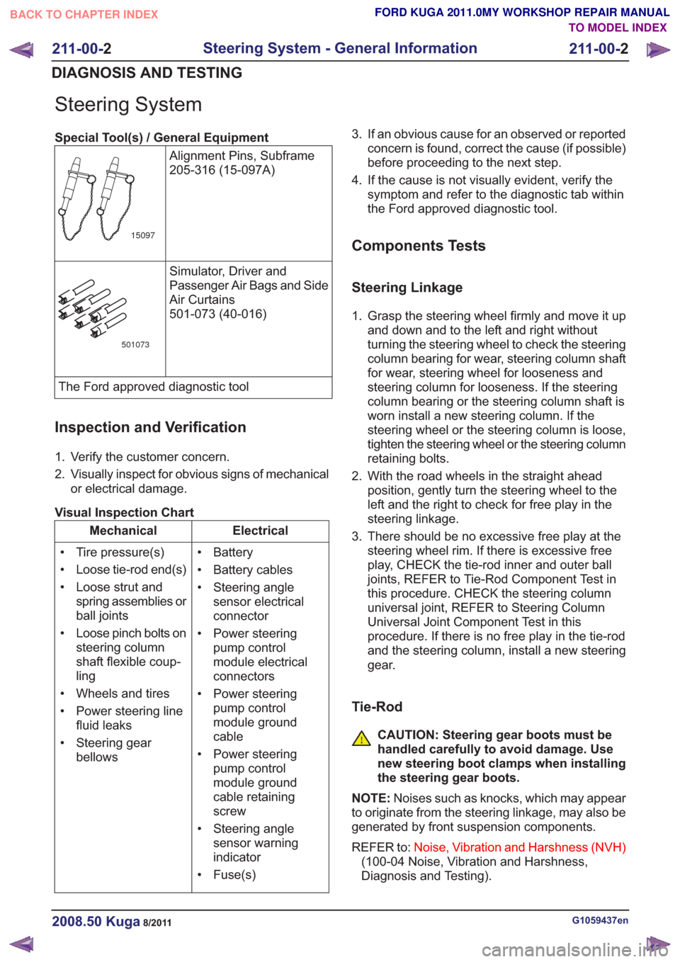
Special Tool(s) / General EquipmentAlignment Pins, Subframe
205-316 (15-097A)
15097
Simulator, Driver and
Passenger Air Bags and Side
Air Curtains
501-073 (40-016)
501073
The Ford approved diagnostic tool
Inspection and Verification
1. Verify the customer concern.
2. Visually inspect for obvious signs of mechanicalor electrical damage.
Visual Inspection Chart
Electrical
Mechanical
• Battery
• Battery cables
• Steering anglesensor electrical
connector
• Power steering pump control
module electrical
connectors
• Power steering pump control
module ground
cable
• Power steering pump control
module ground
cable retaining
screw
• Steering angle sensor warning
indicator
• Fuse(s)
• Tire pressure(s)
• Loose tie-rod end(s)
• Loose strut and
spring assemblies or
ball joints
• Loose pinch bolts on steering column
shaft flexible coup-
ling
• Wheels and tires
• Power steering line fluid leaks
• Steering gear bellows 3. If an obvious cause for an observed or reported
concern is found, correct the cause (if possible)
before proceeding to the next step.
4. If the cause is not visually evident, verify the symptom and refer to the diagnostic tab within
the Ford approved diagnostic tool.
Components Tests
Steering Linkage
1. Grasp the steering wheel firmly and move it upand down and to the left and right without
turning the steering wheel to check the steering
column bearing for wear, steering column shaft
for wear, steering wheel for looseness and
steering column for looseness. If the steering
column bearing or the steering column shaft is
worn install a new steering column. If the
steering wheel or the steering column is loose,
tighten the steering wheel or the steering column
retaining bolts.
2. With the road wheels in the straight ahead position, gently turn the steering wheel to the
left and the right to check for free play in the
steering linkage.
3. There should be no excessive free play at the steering wheel rim. If there is excessive free
play, CHECK the tie-rod inner and outer ball
joints, REFER to Tie-Rod Component Test in
this procedure. CHECK the steering column
universal joint, REFER to Steering Column
Universal Joint Component Test in this
procedure. If there is no free play in the tie-rod
and the steering column, install a new steering
gear.
Tie-Rod
CAUTION: Steering gear boots must be
handled carefully to avoid damage. Use
new steering boot clamps when installing
the steering gear boots.
NOTE: Noises such as knocks, which may appear
to originate from the steering linkage, may also be
generated by front suspension components.
REFER to: Noise, Vibration and Harshness (NVH)
(100-04 Noise, Vibration and Harshness,
Diagnosis and Testing).
G1059437en2008.50 Kuga8/2011
211-00- 2
Steering System - General Information
211-00- 2
DIAGNOSIS AND TESTING
TO MODEL INDEX
BACK TO CHAPTER INDEX
FORD KUGA 2011.0MY WORKSHOP REPAIR MANUAL