2011 FORD KUGA brake fluid
[x] Cancel search: brake fluidPage 1402 of 2057
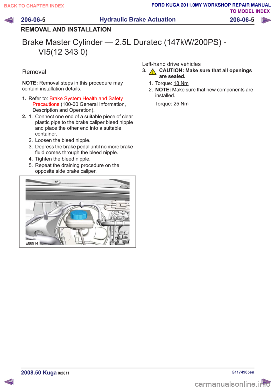
Brake Master Cylinder — 2.5L Duratec (147kW/200PS) -VI5(12 343 0)
Removal
NOTE: Removal steps in this procedure may
contain installation details.
1. Refer to: Brake System Health and Safety
Precautions (100-00 General Information,
Description and Operation).
2. Connect one end of a suitable piece of clear
plastic pipe to the brake caliper bleed nipple
1.
and place the other end into a suitable
container.
2. Loosen the bleed nipple.
3. Depress the brake pedal until no more brake fluid comes through the bleed nipple.
4. Tighten the bleed nipple.
5. Repeat the draining procedure on the opposite side brake caliper.
E86914
Left-hand drive vehicles
3. CAUTION: Make sure that all openings are sealed.
1. Torque: 18Nm
2.NOTE: Make sure that new components are
installed.
Torque: 25
Nm
G1174985en2008.50 Kuga8/2011
206-06- 5
Hydraulic Brake Actuation
206-06- 5
REMOVAL AND INSTALLATION
TO MODEL INDEX
BACK TO CHAPTER INDEX
FORD KUGA 2011.0MY WORKSHOP REPAIR MANUAL
Page 1422 of 2057
Description
Item
Front wheel sensor, right-hand side
8Description
Item
9 ESP switch
Testing the brakes on a roller dynamometer
- 4X4 vehicles only
On 4X4 vehicles a brake test on a roller
dynamometer must only be performed under the
following conditions.
• The brake test must not exceed a duration of 1 minute.
• Ignition key in position 0.
• The roller speed must not exceed 5 km/h.
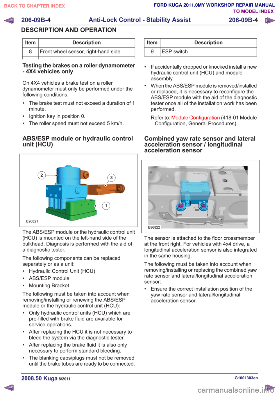
ABS/ESP module or hydraulic control
unit (HCU)
E96821
1
23
The ABS/ESP module or the hydraulic control unit
(HCU) is mounted on the left-hand side of the
bulkhead. Diagnosis is performed with the aid of
a diagnostic tester.
The following components can be replaced
separately or as a unit:
• Hydraulic Control Unit (HCU)
• ABS/ESP module
• Mounting Bracket
The following must be taken into account when
removing/installing or renewing the ABS/ESP
module or the hydraulic control unit (HCU):
• Only hydraulic control units (HCU) which are pre-filled with brake fluid are available for
service operations.
• After replacing the HCU it is not necessary to bleed the system via the diagnostic tester.
• After replacing the brake fluid it is also only necessary to perform standard bleeding.
• The blanking caps/plugs must not be removed until the brake tubes are ready to be connected. • If accidentally dropped or knocked install a new
hydraulic control unit (HCU) and module
assembly.
• When the ABS/ESP module is removed/installed or replaced, it is necessary to reconfigure the
ABS/ESP module with the aid of the diagnostic
tester once all of the installation work has been
performed.
Refer to: Module Configuration (418-01 Module
Configuration, General Procedures).
Combined yaw rate sensor and lateral
acceleration sensor / longitudinal
acceleration sensor
E96822
The sensor is attached to the floor crossmember
at the front right. For vehicles with 4x4 drive, a
longitudinal acceleration sensor is also integrated
in the same housing.
The following must be taken into account when
removing/installing or replacing the combined yaw
rate sensor and lateral/longitudinal acceleration
sensor:
• Ensure the correct installation position of the yaw rate sensor and lateral/longitudinal
acceleration sensor.
G1001303en2008.50 Kuga8/2011
206-09B- 4
Anti-Lock Control - Stability Assist
206-09B- 4
DESCRIPTION AND OPERATION
TO MODEL INDEX
BACK TO CHAPTER INDEX
FORD KUGA 2011.0MY WORKSHOP REPAIR MANUAL
Page 1426 of 2057
Description
Item
D.C. motor
9
Solenoid-operated pilot valve (2 off)
10
Solenoid-operated priming valve (2 off)
11
One way check valve
12
Low-pressure accumulator (2 off)
13
Solenoid-operated inlet valve (RH rear
brake)
14
Solenoid-operated inlet valve (LH front
brake)
15
Solenoid-operated outlet valve (LH front
brake)
16
Solenoid-operated outlet valve (RH rear
brake)
17Description
Item
Pressure sensor (5 off)
18
LH front brake (secondary circuit)
19
RH rear brake (secondary circuit)
20
LH rear brake (primary circuit)
21
RH front brake (primary circuit)
22
Solenoid-operated outlet valve (RH front
brake)
23
Solenoid-operated outlet valve (LH rear
brake)
24
Solenoid-operated inlet valve (LH rear
brake)
25
Solenoid-operated inlet valve (RH front
brake)
26
System Operation
The HCU features 3 operating modes:
Normal braking:
Initially, no current is supplied to
any of the solenoid-operated valves. Operating the
brake pedal produces a corresponding increase
or decrease of pressure in the brakes, through the
open pilot valves and inlet valves. If the ABS
module determines that EBD is necessary, it
energizes the inlet valves for both the rear brakes,
to isolate the brakes from any further increase in
hydraulic pressure.
ABS braking: If the ABS module determines that
ABS braking is necessary, it actuates the inlet and
outlet valves of the relevant brake and starts the
hydraulic return pump. The inlet valve closes to
isolate the brake from pressurized fluid; the outlet
valve opens to release pressure from the brake
into the accumulator and the return pump circuit.
The brake releases slightly and the wheel starts to turn again. The ABS control unit then operates the
inlet and outlet valves to regulate the hydraulic
pressure acting on the brake in order to maximize
braking effect without the wheel locking up. Control
of the valves for each wheel takes place
individually.
Active braking:
With active braking, pressure is
generated for other braking functions than the
normal and ABS braking systems, e.g. for the ESP
and TCS systems. For active braking, the ABS
module energizes the pilot valves and priming
valves, starts the return pump and energizes all of
the inlet valves. Brake fluid, drawn from the
reservoir through the master cylinder and priming
valve, is pressurized by the return pump and
supplied to the inlet valves. The ABS control unit
then actuates the inlet and outlet valves in order
to regulate the pressure for the individual brakes.
Some noise may be generated during active
braking.
G1001304en2008.50 Kuga8/2011
206-09B- 8
Anti-Lock Control - Stability Assist
206-09B- 8
DESCRIPTION AND OPERATION
TO MODEL INDEX
BACK TO CHAPTER INDEX
FORD KUGA 2011.0MY WORKSHOP REPAIR MANUAL
Page 1430 of 2057
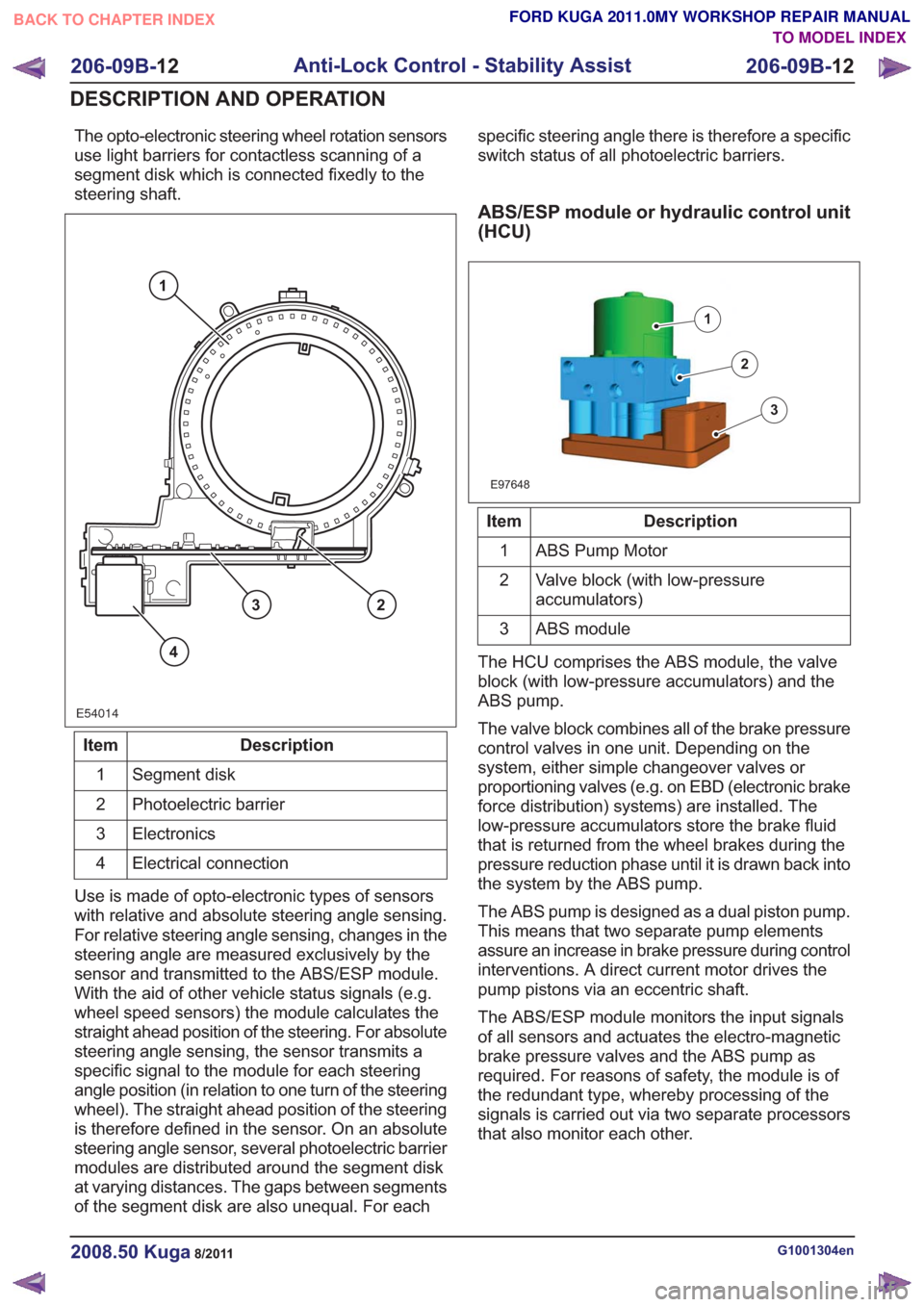
The opto-electronic steering wheel rotation sensors
use light barriers for contactless scanning of a
segment disk which is connected fixedly to the
steering shaft.
E54014
1
23
4
Description
Item
Segment disk
1
Photoelectric barrier
2
Electronics
3
Electrical connection
4
Use is made of opto-electronic types of sensors
with relative and absolute steering angle sensing.
For relative steering angle sensing, changes in the
steering angle are measured exclusively by the
sensor and transmitted to the ABS/ESP module.
With the aid of other vehicle status signals (e.g.
wheel speed sensors) the module calculates the
straight ahead position of the steering. For absolute
steering angle sensing, the sensor transmits a
specific signal to the module for each steering
angle position (in relation to one turn of the steering
wheel). The straight ahead position of the steering
is therefore defined in the sensor. On an absolute
steering angle sensor, several photoelectric barrier
modules are distributed around the segment disk
at varying distances. The gaps between segments
of the segment disk are also unequal. For each specific steering angle there is therefore a specific
switch status of all photoelectric barriers.
ABS/ESP module or hydraulic control unit
(HCU)
E97648
1
2
3
Description
Item
ABS Pump Motor
1
Valve block (with low-pressure
accumulators)
2
ABS module
3
The HCU comprises the ABS module, the valve
block (with low-pressure accumulators) and the
ABS pump.
The valve block combines all of the brake pressure
control valves in one unit. Depending on the
system, either simple changeover valves or
proportioning valves (e.g. on EBD (electronic brake
force distribution) systems) are installed. The
low-pressure accumulators store the brake fluid
that is returned from the wheel brakes during the
pressure reduction phase until it is drawn back into
the system by the ABS pump.
The ABS pump is designed as a dual piston pump.
This means that two separate pump elements
assure an increase in brake pressure during control
interventions. A direct current motor drives the
pump pistons via an eccentric shaft.
The ABS/ESP module monitors the input signals
of all sensors and actuates the electro-magnetic
brake pressure valves and the ABS pump as
required. For reasons of safety, the module is of
the redundant type, whereby processing of the
signals is carried out via two separate processors
that also monitor each other.
G1001304en2008.50 Kuga8/2011
206-09B- 12
Anti-Lock Control - Stability Assist
206-09B- 12
DESCRIPTION AND OPERATION
TO MODEL INDEX
BACK TO CHAPTER INDEX
FORD KUGA 2011.0MY WORKSHOP REPAIR MANUAL
Page 1434 of 2057
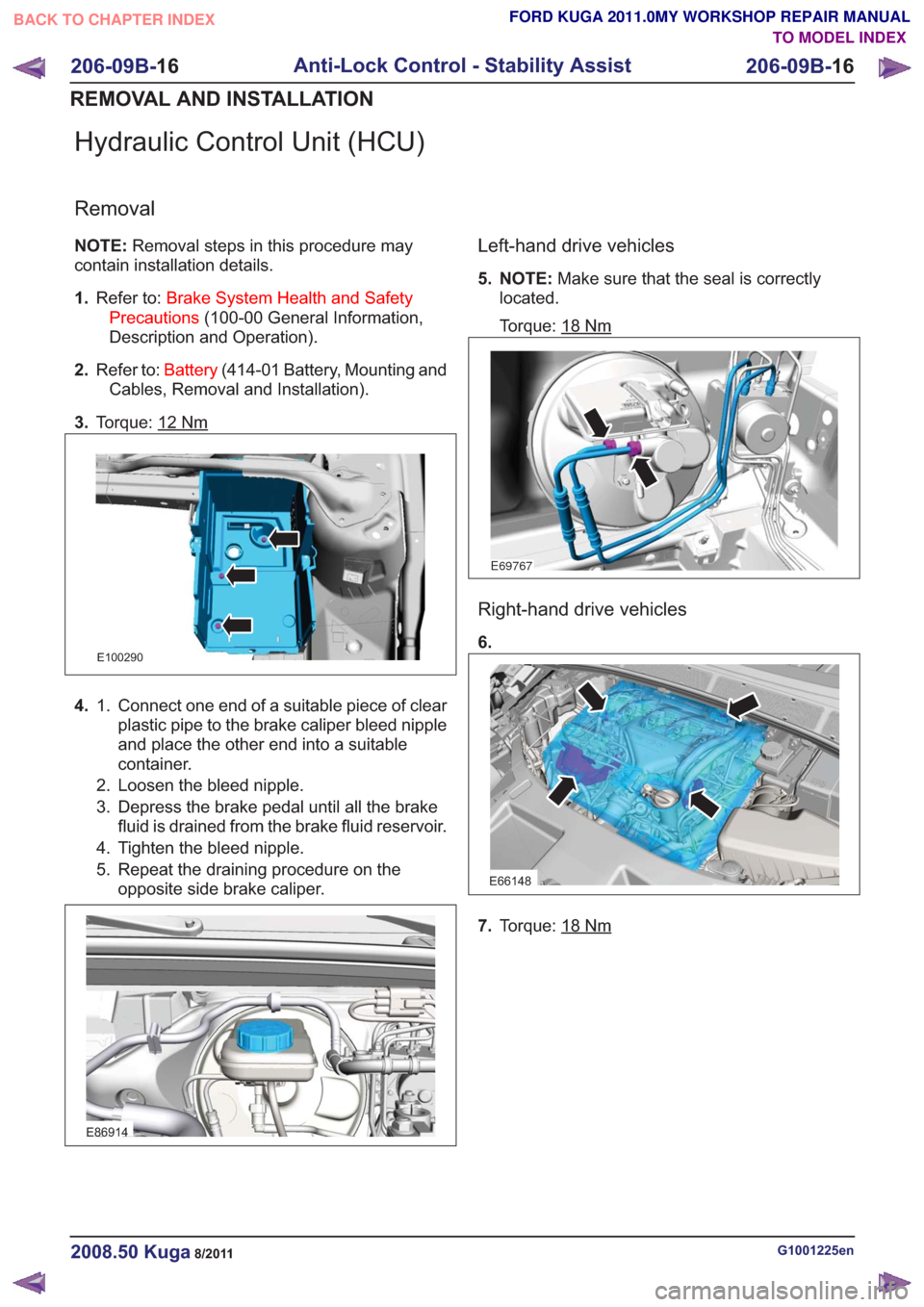
Hydraulic Control Unit (HCU)
Removal
NOTE:Removal steps in this procedure may
contain installation details.
1. Refer to: Brake System Health and Safety
Precautions (100-00 General Information,
Description and Operation).
2. Refer to: Battery(414-01 Battery, Mounting and
Cables, Removal and Installation).
3. Torque: 12
Nm
E100290
4. Connect one end of a suitable piece of clear
plastic pipe to the brake caliper bleed nipple
1.
and place the other end into a suitable
container.
2. Loosen the bleed nipple.
3. Depress the brake pedal until all the brake fluid is drained from the brake fluid reservoir.
4. Tighten the bleed nipple.
5. Repeat the draining procedure on the opposite side brake caliper.
E86914
Left-hand drive vehicles
5. NOTE: Make sure that the seal is correctly
located.
Torque: 18
Nm
E69767
Right-hand drive vehicles
6.
E66148
7. Torque: 18Nm
G1001225en2008.50 Kuga8/2011
206-09B- 16
Anti-Lock Control - Stability Assist
206-09B- 16
REMOVAL AND INSTALLATION
TO MODEL INDEX
BACK TO CHAPTER INDEX
FORD KUGA 2011.0MY WORKSHOP REPAIR MANUAL
Page 1445 of 2057
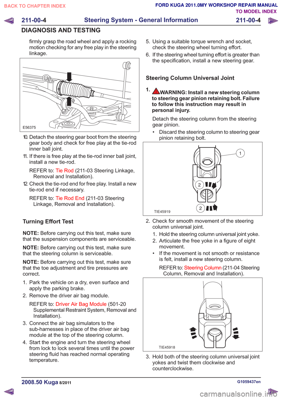
firmly grasp the road wheel and apply a rocking
motion checking for any free play in the steering
linkage.
E56375
10. Detach the steering gear boot from the steeringgear body and check for free play at the tie-rod
inner ball joint.
11. If there is free play at the tie-rod inner ball joint, install a new tie-rod.
REFER to: Tie Rod(211-03 Steering Linkage,
Removal and Installation).
12. Check the tie-rod end for free play. Install a new tie-rod end if necessary.
REFER to: Tie Rod End (211-03 Steering
Linkage, Removal and Installation).
Turning Effort Test
NOTE: Before carrying out this test, make sure
that the suspension components are serviceable.
NOTE: Before carrying out this test, make sure
that the steering column is serviceable.
NOTE: Before carrying out this test, make sure
that the toe adjustment and tire pressures are
correct.
1. Park the vehicle on a dry, even surface and apply the parking brake.
2. Remove the driver air bag module.
REFER to: Driver Air Bag Module (501-20
Supplemental Restraint System, Removal and
Installation).
3. Connect the air bag simulators to the sub-harnesses in place of the driver air bag
module at the top of the steering column.
4. Start the engine and turn the steering wheel from lock to lock several times until the power
steering fluid has reached normal operating
temperature. 5. Using a suitable torque wrench and socket,
check the steering wheel turning effort.
6. If the steering wheel turning effort is greater than the specification, install a new steering gear.
Steering Column Universal Joint
1.WARNING: Install a new steering column
to steering gear pinion retaining bolt. Failure
to follow this instruction may result in
personal injury.
Detach the steering column from the steering
gear pinion.• Discard the steering column to steering gear pinion retaining bolt.
TIE45919
1
2
2
2. Check for smooth movement of the steeringcolumn universal joint.
1. Hold the steering column universal joint yoke.
2. Articulate the free yoke in a figure of eight movement.
• If the movement is not smooth or resistance is felt, install a new steering column.
REFER to: Steering Column (211-04 Steering
Column, Removal and Installation).
TIE45918
3. Hold both of the steering column universal joint yokes and twist them clockwise and
counterclockwise.
G1059437en2008.50 Kuga8/2011
211-00- 4
Steering System - General Information
211-00- 4
DIAGNOSIS AND TESTING
TO MODEL INDEX
BACK TO CHAPTER INDEX
FORD KUGA 2011.0MY WORKSHOP REPAIR MANUAL
Page 1822 of 2057
SECTION 307-01 Automatic Transmission/Transaxle
— Vehicles With: 5-Speed Automatic Transaxle - AW55 AWD
VEHICLE APPLICATION:2008.50 Kuga
PA G E
CONTENTS
SPECIFICATIONS
307-01-4
Specifications ........................................................................\
..............................................
DESCRIPTION AND OPERATION 307-01-5
Transmission Description (Component Location) ...............................................................
307-01-6
Transmission Description (Overview) ........................................................................\
.........
307-01-6
Components of the AW55 automatic transaxle ..................................................................
307-01-6
General overview ........................................................................\
....................................
307-01-8
Transaxle cooling ........................................................................\
....................................
307-01-8
External shift mechanism ........................................................................\
........................
307-01-9
Components of the electronic control ........................................................................\
.....
307-01-11
Overview of the brakes, clutches and one-way clutches ................................................
307-01-12
Input and output signals at the TCM ........................................................................\
.......
307-01-14
Knowing and Understanding Customer Concerns ..........................................................
307-01-14
Testing Possible Causes of Transmission Control Faults ...............................................
307-01-14
IDS Diagnosis ........................................................................\
.........................................
307-01-14
visual inspection ........................................................................\
.....................................
307-01-15
Towing the vehicle ........................................................................\
..................................
307-01-15
Push-starting the Vehicle ........................................................................\
........................
307-01-15
Jump-starting the Vehicle ........................................................................\
.......................
307-01-15
Selector Lever Emergency Release ........................................................................\
.......
307-01-16
Adjusting the Selector Lever Cable ........................................................................\
........
307-01-17
Transmission Fluid Level Check ........................................................................\
.............
307-01-17
Changing the Transmission Fluid ........................................................................\
...........
307-01-18
Diagnosis with IDS ........................................................................\
..................................
307-01-19
Resetting the counter for fluid change intervals. .............................................................
307-01-19
Programming the 'N' position of the TR sensor..............................................................
307-01-19
Resetting the values learned by the TCM .......................................................................
307-01-21
Transmission Description (System Operation and Component Description) .....................
307-01-21
System Operation ........................................................................\
.......................................
307-01-22
Functionality overview ........................................................................\
............................
307-01-24
Electronic Control System ........................................................................\
......................
307-01-24
Hydraulic Control System ........................................................................\
.......................
307-01-24
Type plate ........................................................................\
...............................................
307-01-25
Serial number of the transmission ........................................................................\
..........
307-01-25
Markings on the TCM ........................................................................\
.............................
307-01-25
Serial
number of the TCM ........................................................................\
.......................
307-01-25
Transmission Control ........................................................................\
..............................
307-01-27
Pin assignment for TCM connector 'C' (connection to transaxle) ...................................
307-01-28
Operation ........................................................................\
................................................
307-01-29
Gearshift control ........................................................................\
......................................
307-01-29
Adaptation ........................................................................\
...............................................
307-01-29
Shifting from 'P' to another transmission range ..............................................................
307-01-1
Automatic Transmission/Transaxle
— Vehicles With:
5-Speed Automatic Transaxle - AW55 AWD
307-01- 1
.
TO MODEL INDEX
BACK TO CHAPTER INDEX
PAGE 1 OF 3 FORD KUGA 2011.0MY WORKSHOP REPAIR MANUAL
Page 1823 of 2057
307-01-29
Automatic transmission, selector lever in position "D". ...................................................
307-01-29
Sport mode, selector lever in position "S" .......................................................................
307-01-29
Changing gear in select-shift mode........................................................................\
........
307-01-30
Selector lever from 'N' to 'R' position ........................................................................\
......
307-01-30
Self-test and Diagnosis ........................................................................\
...........................
307-01-30
Temperature controlled torque converter lockup ............................................................
307-01-30
Slip locking ........................................................................\
..............................................
307-01-30
Hill climbing ........................................................................\
.............................................
307-01-31
Downhill driving ........................................................................\
.......................................
307-01-31
Hill-hold function ........................................................................\
.....................................
307-01-31
Altitude correction ........................................................................\
...................................
307-01-31
Selector lever lock ........................................................................\
..................................
307-01-31
Shifting from P into another transmission range .............................................................
307-01-31
Shifting from N into another transmission range .............................................................
307-01-31
Power flow through the transmission ........................................................................\
......
307-01-31
Clutches and brakes ........................................................................\
...............................
307-01-33
Position P (park) ........................................................................\
.....................................
307-01-34
Position N (neutral) ........................................................................\
.................................
307-01-35
Position D, 1st gear........................................................................\
................................
307-01-36
Position D, 2nd gear ........................................................................\
...............................
307-01-37
Position D, 3rd gear ........................................................................\
................................
307-01-38
Position D, 4th gear ........................................................................\
................................
307-01-39
Position D, 5th gear ........................................................................\
................................
307-01-40
Position R (reverse) ........................................................................\
................................
307-01-41
Service instructions ........................................................................\
.................................
307-01-41
Towing procedure ........................................................................\
...................................
307-01-42
Reset adaptation data ........................................................................\
.............................
307-01-42
Limp home mode ........................................................................\
....................................
307-01-42
Component Description ........................................................................\
..............................
Tasks of the electronic components ........................................................................\
........
307-01-44
Input signals ........................................................................\
............................................
307-01-45
Output signals ........................................................................\
.........................................
Control valve assembly ........................................................................\
...........................
Shift solenoids S1 - S5 ........................................................................\
...........................
PWM-
solenoid valve – TCC (SLU) ........................................................................\
........
PWM solenoid valve – shift pressure (SLS) ...................................................................
PWM solenoid valve for main line pressure (SLT) ..........................................................
307-01-52
Installation position ........................................................................\
.................................
Operation ........................................................................\
................................................
Selector lever with integrated select-shift switch module ...............................................
Oil pump ........................................................................\
..................................................
Torque converter with TCC ........................................................................\
.....................
The TSS sensor ........................................................................\
......................................
The OSS sensor ........................................................................\
.....................................
The TFT sensor ........................................................................\
......................................
The TR sensor ........................................................................\
........................................
GENERAL PROCEDURES
T ransmission Fluid Level Check ........................................................................\
.................
307-01-63
T ransmission Fluid Drain and Refill ........................................................................\
............
REMOVAL AND INSTALLATION 307-01-67
Halfshaft Seal LH ........................................................................\
........................................
307-01-68
Halfshaft Seal RH........................................................................\
.......................................
307-01-69
Main Control Valve Body ........................................................................\
............................
307-01-2
Automatic Transmission/Transaxle
— Vehicles With:
5-Speed Automatic Transaxle - AW55 AWD
307-01- 2
.
TO MODEL INDEX
BACK TO CHAPTER INDEX
307-01-42
307-01-49
307-01-52 307-01-47
307-01-45
307-01-50
307-01-51
307-01-53
307-01-55
307-01-54
307-01-56
307-01-57
307-01-58
307-01-61 307-01-60
PAGE 2 OF 3 FORD KUGA 2011.0MY WORKSHOP REPAIR MANUAL