Page 1992 of 2057
Fuel Tank Filler Pipe
General EquipmentFluid ContainerGeneral EquipmentFuel Tank Draining Equipment
Hose Clamp Remover/Installer
Removal
WARNING: Make sure that the fuel tank is
no more than 3/4 full.
NOTE: Removal steps in this procedure may
contain installation details.
1. Remove the rear wheel on right-hand side.
Refer to: Wheel and Tire (204-04 Wheels and
Tires, Removal and Installation).
2. WARNING: Be prepared to collect escaping fluid.
CAUTION: Use suitable paper to absorb
any escaping fluid.
General Equipment: Hose Clamp Remover/Installer
E117531
3. Torque: 10Nm
x2x2
E117532
G1000790en2008.50 Kuga8/2011
310-01- 12
Fuel Tank and Lines
310-01- 12
REMOVAL AND INSTALLATION
TO MODEL INDEX
BACK TO CHAPTER INDEX
FORD KUGA 2011.0MY WORKSHOP REPAIR MANUAL
Page 1993 of 2057
4. WARNING: Fuel may still be present inthe fuel tank after draining.
1. Make sure, that the fuel filler pipe is abovethe fuel level.
General Equipment: Hose ClampRemover/Installer
2. Drain the reservoir.
General Equipment: Fuel Tank DrainingEquipment
General Equipment: Fluid Container
E126409
12
Installation
1. To install, reverse the removal procedure. 2. NOTE:
Make sure that a new component is
installed.
1.
NOTE: Make sure that a new clamp is
installed.
NOTE: Make sure that the clamp is installed
to the same orientation as when removed.
General Equipment: Hose Clamp Remover/Installer
2. NOTE: Make sure that a new clamp is
installed.
NOTE: Make sure that the clamp is installed
to the same orientation as when removed.
General Equipment: Hose Clamp Remover/Installer
1
2
E117533
G1000790en2008.50 Kuga8/2011
310-01- 13
Fuel Tank and Lines
310-01- 13
REMOVAL AND INSTALLATION
TO MODEL INDEX
BACK TO CHAPTER INDEX
FORD KUGA 2011.0MY WORKSHOP REPAIR MANUAL
Page 2037 of 2057

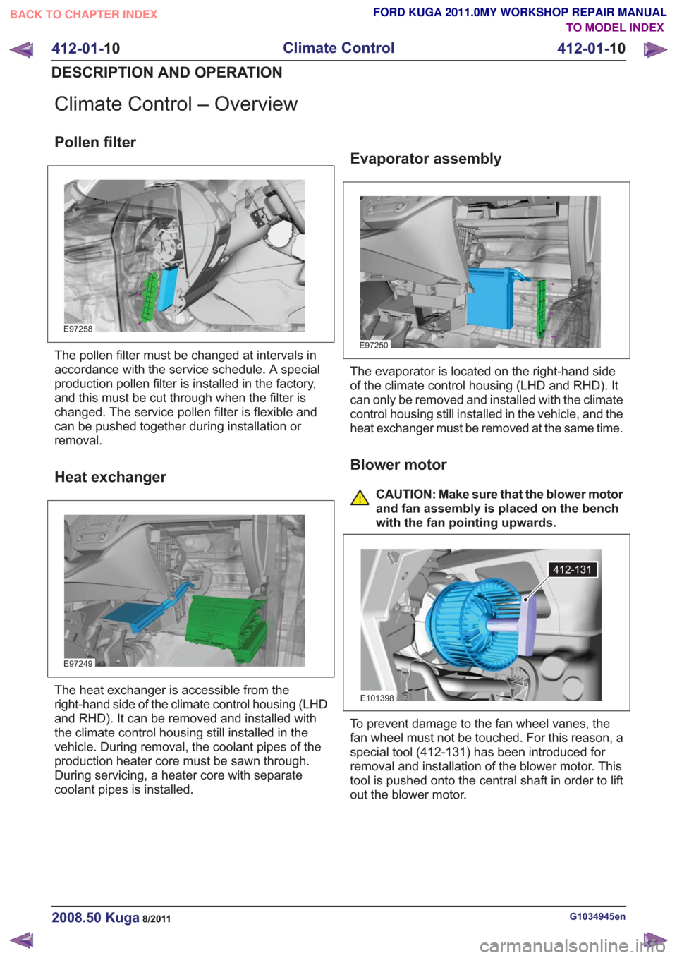
Climate Control – Overview
Pollen filter
E97258
The pollen filter must be changed at intervals in
accordance with the service schedule. A special
production pollen filter is installed in the factory,
and this must be cut through when the filter is
changed. The service pollen filter is flexible and
can be pushed together during installation or
removal.
Heat exchanger
E97249
The heat exchanger is accessible from the
right-hand side of the climate control housing (LHD
and RHD). It can be removed and installed with
the climate control housing still installed in the
vehicle. During removal, the coolant pipes of the
production heater core must be sawn through.
During servicing, a heater core with separate
coolant pipes is installed.
Evaporator assembly
E97250
The evaporator is located on the right-hand side
of the climate control housing (LHD and RHD). It
can only be removed and installed with the climate
control housing still installed in the vehicle, and the
heat exchanger must be removed at the same time.
Blower motor
CAUTION: Make sure that the blower motor
and fan assembly is placed on the bench
with the fan pointing upwards.
412-131
E101398
To prevent damage to the fan wheel vanes, the
fan wheel must not be touched. For this reason, a
special tool (412-131) has been introduced for
removal and installation of the blower motor. This
tool is pushed onto the central shaft in order to lift
out the blower motor.
G1034945en2008.50 Kuga8/2011
412-01-10
Climate Control
412-01- 10
DESCRIPTION AND OPERATION
TO MODEL INDEX
BACK TO CHAPTER INDEX
FORD KUGA 2011.0MY WORKSHOP REPAIR MANUAL