Page 1681 of 2057

Coolant Pump — 2.5L Duratec (147kW/200PS) - VI5(24 404 0)
General EquipmentTrolley Jack
Removal
NOTE: Removal steps in this procedure may
contain installation details.
1. Drain the cooling system.
Refer to: Cooling System Draining and Vacuum
Filling (303-03 Engine Cooling, General
Procedures).
2. Remove the timing belt.
Refer to: Timing Belt (303-01 Engine - 2.5L
Duratec (147kW/200PS) - VI5, Removal and
Installation).
3. CAUTION: Use a wooden block to protect the oil pan when supporting the
engine.
Position the trolley jack with the wooden block
under the oil pan. Raise the trolley jack until the
front of the engine is free from load and the
coolant pump bolts can be accessed.
General Equipment: Trolley Jack
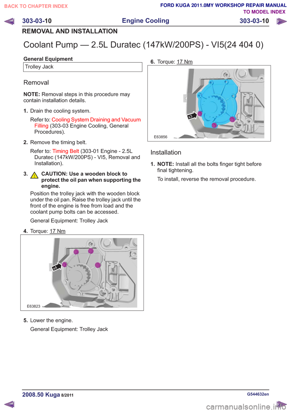
4. Torque: 17
Nm
E63823
x4
5.Lower the engine.
General Equipment: Trolley Jack 6.
Torque: 17
Nm
x3
E63856
Installation
1. NOTE: Install all the bolts finger tight before
final tightening.
To install, reverse the removal procedure.
G544632en2008.50 Kuga8/2011
303-03- 10
Engine Cooling
303-03- 10
REMOVAL AND INSTALLATION
TO MODEL INDEX
BACK TO CHAPTER INDEX
FORD KUGA 2011.0MY WORKSHOP REPAIR MANUAL
Page 1685 of 2057
Radiator — 2.5L Duratec (147kW/200PS) - VI5(24 254 0)
General EquipmentCable Ties
Hose Clamp Remover/Installer
Removal
NOTE: Removal steps in this procedure may
contain installation details.
1.
E112311
2.
E112335
3. Refer to: Charge Air Cooler (303-12 Intake Air
Distribution and Filtering - 2.5L Duratec
(147kW/200PS) - VI5, Removal and
Installation).
4. Refer to: Cooling System Draining and Vacuum
Filling (303-03 Engine Cooling, General
Procedures).
5. Torque: 25
Nm
E112625
x2x2
6. NOTE: The gasket is to be reused unless
damaged.
E99980
Vehicles with automatic transmission
7. General Equipment: Cable Ties
G1156381en2008.50 Kuga8/2011
303-03- 14
Engine Cooling
303-03- 14
REMOVAL AND INSTALLATION
TO MODEL INDEX
BACK TO CHAPTER INDEX
FORD KUGA 2011.0MY WORKSHOP REPAIR MANUAL
Page 1690 of 2057
Thermostat — 2.5L Duratec (147kW/200PS) - VI5(24 454 0)
Removal
NOTE:Removal steps in this procedure may
contain installation details.
1. Refer to: Cooling System Draining and Vacuum
Filling (303-03 Engine Cooling, General
Procedures).
2. Refer to: Air Cleaner (303-12 Intake Air
Distribution and Filtering - 2.5L Duratec
(147kW/200PS) - VI5, Removal and
Installation).
3.
E64638
4. Torque: 8Nm
E64639
x3
5.
E64640
Installation
1.To install, reverse the removal procedure.
G962443en2008.50 Kuga8/2011
303-03- 19
Engine Cooling
303-03- 19
REMOVAL AND INSTALLATION
TO MODEL INDEX
BACK TO CHAPTER INDEX
FORD KUGA 2011.0MY WORKSHOP REPAIR MANUAL
Page 1691 of 2057
Thermostat Housing — 2.5L Duratec (147kW/200PS) -VI5(24 001 0)
Removal
NOTE: Removal steps in this procedure may
contain installation details.
1. Refer to: Cooling System Draining and Vacuum
Filling (303-03 Engine Cooling, General
Procedures).
2. Refer to: Air Cleaner (303-12 Intake Air
Distribution and Filtering - 2.5L Duratec
(147kW/200PS) - VI5, Removal and
Installation).
3. Torque: 17
Nm
E63828
2
4
x3
1
3
4.
E67780
Installation
1.To install, reverse the removal procedure.
G962444en2008.50 Kuga8/2011
303-03- 20
Engine Cooling
303-03- 20
REMOVAL AND INSTALLATION
TO MODEL INDEX
BACK TO CHAPTER INDEX
FORD KUGA 2011.0MY WORKSHOP REPAIR MANUAL
Page 1695 of 2057

Fuel Charging and Controls
General EquipmentFord diagnostic equipment
Inspection and Verification
1. Verify the customer concern by operating the system.
2. Visually inspect for obvious signs of mechanical or electrical damage. Visual Inspection Chart
Electrical
Mechanical
– Loose or corrodedconnector(s)
– Wiring harness
– Fuel injector(s)
– Fuel leaks
– Blocked or contamin-
ated fuel filter
– Damaged fuel supply manifold
– Damaged fuel line connections
– Damaged vacuum hoses
– Fuel rail pressure sensor
3. If an obvious cause for an observed or reported concern is found, correct the cause (if possible)
before proceeding to the next step.
4. If the concern is not visually evident, verify the symptom and refer to the Ford diagnostic
equipment .
Symptom Chart
Action
Possible Sources
Symptom
• CHECK the PATS LED extin-guishes within 3 seconds when
the ignition is turned on.
REFER to: Anti-Theft - Passive
(419-01 Anti-Theft - Passive,
Diagnosis and Testing).
• PAT S .
• Engine does not crank
• REFER to:Starting System
(303-06 Starting System -
2.5L Duratec (147kW/200PS)
- VI5, Diagnosis and Testing).
• Starting system.
• REFER to the Wiring Diagrams.
• Ignition switch.
• Carry out a full enginediagnosis using the guided
diagnostic menu in the Ford
diagnostic equipment.
• Powertrain control module
(PCM).
• RESET the IFS switch.
• Inertia fuel shutoff (IFS) switch.
• Engine cranks but does not
start
• Check the fuel system pres-sure.
• Low fuel system pressure.
G1183441en2008.50 Kuga8/2011
303-04A-
4
Fuel Charging and Controls
— 2.5L Duratec (147kW/200PS) -
VI5
303-04A- 4
DIAGNOSIS AND TESTING
TO MODEL INDEX
BACK TO CHAPTER INDEX
FORD KUGA 2011.0MY WORKSHOP REPAIR MANUAL
Page 1719 of 2057
6
79108
123
4
5
6
79108
E97592
Description
Item
Exhaust manifold
1
PCV (positive crankcase ventilation)- hose
Comments:to cylinder head
2
Vacuum line - recirculated air valve
Comments:to intake manifold
3
Coolant return pipe
4Description
Item
Turbo boost pressure controller
5
Oil supply pipe - TC
6
Wastegate control valve
7
TC
Comments:Contains the recirculated air valve
8
Coolant supply pipe
9
Oil return pipe - TC
10
G1032424en2008.50 Kuga8/2011
303-04B- 3
Fuel Charging and Controls - Turbocharger
—
2.5L Duratec (147kW/200PS) - VI5
303-04B- 3
DESCRIPTION AND OPERATION
TO MODEL INDEX
BACK TO CHAPTER INDEX
FORD KUGA 2011.0MY WORKSHOP REPAIR MANUAL
Page 1722 of 2057

Description
Item
PWM (pulse width modulation) signal
Comments:from PCM (powertrain control module)
5
Atmospheric pressure
6
Turbocharger boost pressure.
7
from air filter
8
Intake air
9Description
Item
Recirculated air valveRefertoComponentDescription:(page
7)
10
Vacuum line, recirculated air valve
11
to intake manifold
12
Throttle plate
13
Compressor
14
Turbine
15
System Operation
Turbocharger(s)
The TC consists of a turbine and a compressor.
The turbine is driven by the exhaust gas flow. A
common shaft drives the compressor and this then
compresses the intake air.
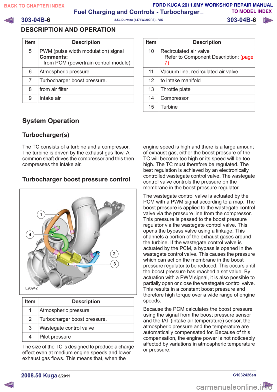
Turbocharger boost pressure control
E98942
1
2
3
4
Description
Item
Atmospheric pressure
1
Turbocharger boost pressure.
2
Wastegate control valve
3
Pilot pressure
4
The size of the TC is designed to produce a charge
effect even at medium engine speeds and lower
exhaust gas flows. This means that, when the engine speed is high and there is a large amount
of exhaust gas, either the boost pressure of the
TC will become too high or its speed will be too
high. The TC must therefore be regulated. The
best regulation is achieved by an electronically
controlled wastegate control valve. The wastegate
control valve controls the pressure on the
membrane in the boost pressure regulator.
The wastegate control valve is actuated by the
PCM with a PWM signal according to a map. The
boost pressure is applied to the wastegate control
valve via the pressure line from the compressor.
This pressure is passed to the boost pressure
regulator via the wastegate control valve. This
opens the bypass valve using a linkage. This
channels a portion of the exhaust gases around
the turbine. If the wastegate control valve is
actuated by the PCM, a bypass is opened in the
wastegate control valve. This causes the pressure
which can act on the membrane in the boost
pressure regulator to be reduced. This occurs until
the boost pressure has reached a set value. By
actuation with a PWM signal, it is also possible to
partially open or close the wastegate control valve.
This results in a constant boost pressure and
therefore high torque over a wide range of engine
speeds.
Because the PCM calculates the boost pressure
using the signal from the boost pressure sensor
and the IAT (intake air temperature) sensor, the
atmospheric pressure and the temperature are
automatically compensated for. Because of this
compensation, the engine power is not noticeably
affected by variations in atmospheric temperature
or pressure.
G1032426en2008.50 Kuga8/2011
303-04B-
6
Fuel Charging and Controls - Turbocharger
—
2.5L Duratec (147kW/200PS) - VI5
303-04B- 6
DESCRIPTION AND OPERATION
TO MODEL INDEX
BACK TO CHAPTER INDEX
FORD KUGA 2011.0MY WORKSHOP REPAIR MANUAL
Page 1723 of 2057

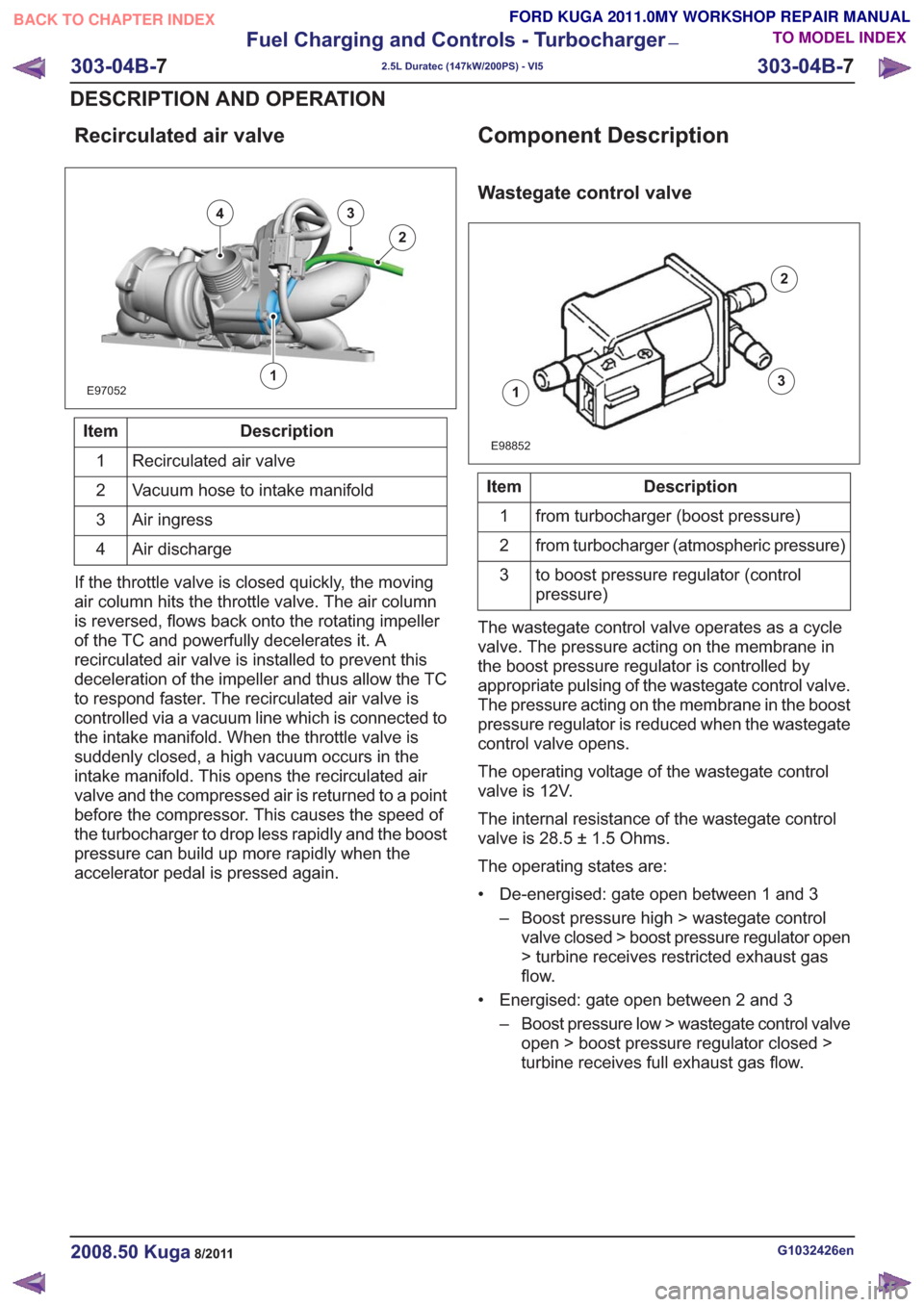
Recirculated air valve
E97052
43
2
1
Description
Item
Recirculated air valve
1
Vacuum hose to intake manifold
2
Air ingress
3
Air discharge
4
If the throttle valve is closed quickly, the moving
air column hits the throttle valve. The air column
is reversed, flows back onto the rotating impeller
of the TC and powerfully decelerates it. A
recirculated air valve is installed to prevent this
deceleration of the impeller and thus allow the TC
to respond faster. The recirculated air valve is
controlled via a vacuum line which is connected to
the intake manifold. When the throttle valve is
suddenly closed, a high vacuum occurs in the
intake manifold. This opens the recirculated air
valve and the compressed air is returned to a point
before the compressor. This causes the speed of
the turbocharger to drop less rapidly and the boost
pressure can build up more rapidly when the
accelerator pedal is pressed again.
Component Description
Wastegate control valve
1
2
3
E98852
Description
Item
from turbocharger (boost pressure)
1
from turbocharger (atmospheric pressure)
2
to boost pressure regulator (control
pressure)
3
The wastegate control valve operates as a cycle
valve. The pressure acting on the membrane in
the boost pressure regulator is controlled by
appropriate pulsing of the wastegate control valve.
The pressure acting on the membrane in the boost
pressure regulator is reduced when the wastegate
control valve opens.
The operating voltage of the wastegate control
valve is 12V.
The internal resistance of the wastegate control
valve is 28.5 ± 1.5 Ohms.
The operating states are:
• De-energised: gate open between 1 and 3 – Boost pressure high > wastegate controlvalve closed > boost pressure regulator open
> turbine receives restricted exhaust gas
flow.
• Energised: gate open between 2 and 3 – Boost pressure low > wastegate control valveopen > boost pressure regulator closed >
turbine receives full exhaust gas flow.
G1032426en2008.50 Kuga8/2011
303-04B- 7
Fuel Charging and Controls - Turbocharger
—
2.5L Duratec (147kW/200PS) - VI5
303-04B- 7
DESCRIPTION AND OPERATION
TO MODEL INDEX
BACK TO CHAPTER INDEX
FORD KUGA 2011.0MY WORKSHOP REPAIR MANUAL