2011 FORD KUGA Throttle
[x] Cancel search: ThrottlePage 1804 of 2057
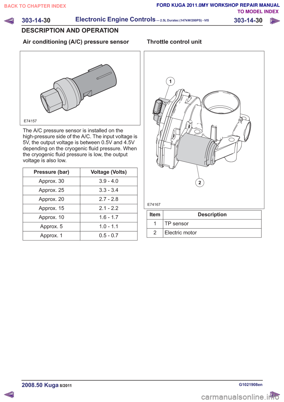
Air conditioning (A/C) pressure sensor
E74157
The A/C pressure sensor is installed on the
high-pressure side of the A/C. The input voltage is
5V, the output voltage is between 0.5V and 4.5V
depending on the cryogenic fluid pressure. When
the cryogenic fluid pressure is low, the output
voltage is also low.
Voltage (Volts)
Pressure (bar)
3.9 - 4.0
Approx. 30
3.3 - 3.4
Approx. 25
2.7 - 2.8
Approx. 20
2.1 - 2.2
Approx. 15
1.6 - 1.7
Approx. 10
1.0 - 1.1
Approx. 5
0.5 - 0.7
Approx. 1
Throttle control unit
E74167
1
2
Description
Item
TP sensor
1
Electric motor
2
G1021908en2008.50 Kuga8/2011
303-14- 30
Electronic Engine Controls— 2.5L Duratec (147kW/200PS) - VI5303-14-
30
DESCRIPTION AND OPERATION
TO MODEL INDEX
BACK TO CHAPTER INDEX
FORD KUGA 2011.0MY WORKSHOP REPAIR MANUAL
Page 1805 of 2057

E74168
1
23456
Description
Item
Stop screw
1
Toothed segment
2
Throttle flap spindle
3
Throttle flap return spring
4
Joint shaft
5
Electric motor with pinion
6
CAUTION: The throttle control unit must
not be repaired or adjusted. The stop of
the throttle valve must on no account be
adjusted.
If there is a fault, the throttle is returned to its
original position by means of the throttle valve
return spring. In this position, the throttle valve is
still slightly open. As a result, a higher idle speed
is set, enabling the vehicle to be driven, though
within narrow limits.
ECT sensor
E94804
The ECT sensor is designed as an NTC resistor.
A voltage of 5V is applied to the ECT sensor by
the PCM. The PCM is able to determine the coolant
temperature from the temperature-dependent
voltage drop at the sensor.
Cooling fan module
E94806
The cooling fan module is directly supplied with
battery power via a 60A fuse in the BJB. The
radiator fan speed is controlled by the PWM via a
PCM signal.
G1021908en2008.50 Kuga8/2011
303-14- 31
Electronic Engine Controls— 2.5L Duratec (147kW/200PS) - VI5303-14-
31
DESCRIPTION AND OPERATION
TO MODEL INDEX
BACK TO CHAPTER INDEX
FORD KUGA 2011.0MY WORKSHOP REPAIR MANUAL
Page 1817 of 2057
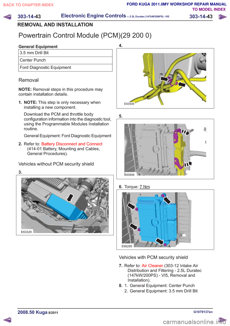
Powertrain Control Module (PCM)(29 200 0)
General Equipment3.5 mm Drill Bit
Center Punch
Ford Diagnostic Equipment
Removal
NOTE: Removal steps in this procedure may
contain installation details.
1. NOTE: This step is only necessary when
installing a new component.
Download the PCM and throttle body
configuration information into the diagnostic tool,
using the Programmable Modules Installation
routine.
General Equipment: Ford Diagnostic Equipment
2. Refer to: Battery Disconnect and Connect
(414-01 Battery, Mounting and Cables,
General Procedures).
Vehicles without PCM security shield
3.
E63329
4.
E93509
5.
E65856
6. Torque: 7Nm
E66285
Vehicles with PCM security shield
7.Refer to: Air Cleaner (303-12 Intake Air
Distribution and Filtering - 2.5L Duratec
(147kW/200PS) - VI5, Removal and
Installation).
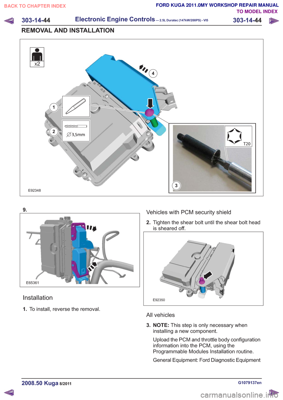
8. General Equipment: Center Punch
1.
2. General Equipment: 3.5 mm Drill Bit
G1079137en2008.50 Kuga8/2011
303-14- 43
Electronic Engine Controls— 2.5L Duratec (147kW/200PS) - VI5303-14-
43
REMOVAL AND INSTALLATION
TO MODEL INDEX
BACK TO CHAPTER INDEX
FORD KUGA 2011.0MY WORKSHOP REPAIR MANUAL
Page 1818 of 2057
E923483
1
2
4
x2
9.
E65361
Installation
1.To install, reverse the removal.
Vehicles with PCM security shield
2.Tighten the shear bolt until the shear bolt head
is sheared off.
E92350
All vehicles
3. NOTE: This step is only necessary when
installing a new component.
Upload the PCM and throttle body configuration
information into the PCM, using the
Programmable Modules Installation routine.
General Equipment: Ford Diagnostic Equipment
G1079137en2008.50 Kuga8/2011
303-14- 44
Electronic Engine Controls— 2.5L Duratec (147kW/200PS) - VI5303-14-
44
REMOVAL AND INSTALLATION
TO MODEL INDEX
BACK TO CHAPTER INDEX
FORD KUGA 2011.0MY WORKSHOP REPAIR MANUAL
Page 1847 of 2057

E112322
The TCM adapts the gear changing to ensure that
the correct gear is selected for the style of driving,
the engine load, driver requirements, vehicle speed
etc. This leads to lower fuel consumption together
with improved comfort through smoother gear
changes and lower noise levels.
The TCM receives information on the driver's
desired transmission range and type of driving
mode. In contrast to a transmission which is only
controlled hydraulically, the control module can
calculate the best times to shift gear and activate
torque converter lockup by using the signals from
the sensors in the transmission and the engine
management system.
The control module enables small changes in the
operating conditions to be made and adapts thevarious transmission functions to ensure that the
correct gear is always selected in relation to the
type of driving mode.
The TCM has adaptive capabilities. This ensures
smooth gear changes throughout the whole service
life of the transmission.
To exactly determine the activation points of the
gear shifts and torque converter lockup on the
basis of the type of driving mode chosen, the TCM
receives the following information:
• Transmission range chosen (TR sensor).
• Type of driving mode chosen
(normal/sport/select-shift).
• Transmission input shaft speed (TSS sensor).
• Transmission output shaft speed (OSS sensor).
• Transmission fluid temperature (TFT sensor).
• The engine speed and the torque as well as the throttle plate opening - from the PCM via the
CAN data bus.
• Actuation of the accelerator pedal - from the PCM via the CAN data bus.
• Coolant temperature - from the PCM via the CAN data bus.
• Vehicle speed - from the ABS via the CAN data bus.
• Actuation of the brake pedal - from the ABS via the CAN data bus.
Pin assignment for TCM connector 'A' (connection to vehicle)
11
E125669
Description
Item
Battery (+)
1
not assigned
2Description
Item
not assigned
3
not assigned
4
G1163605en2008.50 Kuga8/2011
307-01- 26
Automatic Transmission/Transaxle
— Vehicles With:
5-Speed Automatic Transaxle - AW55 AWD
307-01- 26
DESCRIPTION AND OPERATION
TO MODEL INDEX
BACK TO CHAPTER INDEX
FORD KUGA 2011.0MY WORKSHOP REPAIR MANUAL
Page 1850 of 2057
To exactly determine the activation points of the
gear shifts and torque converter lockup on the
basis of the type of driving mode chosen, the TCM
receives the following information:
• Selected transmission range (TR sensor)
• Selected driving mode (normal/sport/select-shift)
• Transmission input shaft speed (TSS sensor)
• Transmission output shaft speed (OSS sensor)
• Transmission fluid temperature (TFT sensor)
• The engine speed and the torque as well as thethrottle plate opening - from the PCM via the
CAN databus
• Actuation of accelerator – from the PCM via the CAN databus
• The coolant temperature – from the PCM via the CAN databus
• Road speed – from the ABS module via the CAN databus
• Actuation of brake pedal – from the PCM via the CAN databus
Gearshift control
Adaptation
The TCM monitors every shift operation in all
driving conditions to make even and smooth gear
shifts possible. This is done by the control module,
which either lowers or increases the hydraulic line
pressure during gearshifts.
The changed pressure values are stored in the
control module memory after the engine is switched
off and retrieved during engine starting. This
improves the shift comfort and extends the service
life.
Full adaptability occurs when the following criteria
are met:
• Throttle plate opening is constant.
• Transmission fluid temperature between 65 °Cand 110 °C.
Shifting from 'P' to another transmission
range
To be able to move the selector lever from 'P' into
another transmission range, the ignition must be
switched on and the brake pedal pressed (stoplamp
switch on). The TCM detects the position of the
brake pedal via the CAN data bus and the engaged
transmission range from the TR sensor. Based on this information, the TCM transmits a
signal to the select-shift switch module. This
activates the brake shift interlock actuator in the
selector lever assembly.
When the brake shift interlock actuator is activated,
the locking pin is retracted so that another
transmission range can be selected.
The brake shift interlock actuator is deactivated
when the ignition is switched off. It is mechanically
locked when the gear selector lever is in 'P'.
Automatic transmission, selector lever in
position "D".
The TCM adapts the shift points to match the
driving conditions. Normally the TCM is in adaptive
mode and gear changes take place adapted to the
driving conditions. If special driving conditions are
detected, the TCM switches to predefined
characteristics.
When driving with normal acceleration, the TCM
uses a preset shift program which is optimized for
economical driving.
This shift program is suitable for "normal" driving
and delivers early upward changes and torque
converter lockup. Furthermore, the transmission
fluid pressure is adapted to make smooth
engagement of the gears possible.
Sport mode, selector lever in position "S"
The transmission switches from automatic
operation into sport mode. In this mode the TCM
switches to another set of characteristic curves.
These characteristic curves for control of the gear
changes are adapted to sporting calculations (e.g.
gear change at higher engine speed).
In the sport mode shift program the shift points are
set so that good performance is offered. Changing
down occurs at lower engine speeds.
Manual gear changes (select-shift mode) can be
made in sport mode by moving the selector lever
in the (+) or (-) direction.
Changing gear in select-shift mode
If you move the selector lever to 'S', the automatic
transaxle remains hydraulically in 'D' position. If
you move the gear selector lever forwards (-), the
G1163605en2008.50 Kuga8/2011
307-01-
29
Automatic Transmission/Transaxle
— Vehicles With:
5-Speed Automatic Transaxle - AW55 AWD
307-01- 29
DESCRIPTION AND OPERATION
TO MODEL INDEX
BACK TO CHAPTER INDEX
FORD KUGA 2011.0MY WORKSHOP REPAIR MANUAL
Page 1851 of 2057
select-shift switch module transmits a downshift
signal to the TCM.
If you move the gear selector lever backwards (+),
an upshift signal is transmitted to the TCM. In the
instrument cluster, the symbol when the selector
lever is in the 'S' position changes from 'D' to the
current gear, for example 3.
The TCM transmits a signal to the select-shift
switch module to switch on the light emitting diode
for 'S' and to switch off all other light emitting
diodes. The TCM decides whether the shift process
is possible.
If the shift process is permitted, then the various
valves are activated according to the intended
combination for each gear.
In certain situations however, the TCM determines
the gear shifting. The following applies:
• If the vehicle is stationary, only 1st, 2nd and 3rdgears can be selected. 4th gear can be selected
at speeds over 30 km/h and 5th gear at speeds
over 40 km/h.
• The kickdown function is only available in the automatic transmission range 'D'
• Automatic gear changes into the next higher or next lower gear occur at fixed vehicle speeds
and fixed engine speeds
• The permitted engine speed for manual change down agree with that for the kickdown change
up, i.e. an engine speed of approximately 6000
rpm.
• If the temperature inside the transmission rises too high, the TCM takes control of the shift
decisions in order to select a gear in which
activation of torque converter lockup at the
current speed is possible
• Torque converter lockup is possible in 3rd, 4th and 5th gear. (1st and 2nd gears do not have
torque converter lockup)
The signal that specifies the position of the lever
to the select-shift switch module is generated as
follows in the selector lever position 'S': there is a
Hall sensor at the printed circuit board for the
module for each of the three selector lever
positions. A permanent magnet on the cover in the
selector lever affects the output signals to the
control module from the sensors. The control
module recognizes the position of the lever by the
differences in the signal properties.Selector lever from 'N' to 'R' position
The TCM only permits shifting to reverse gear if
the vehicle speed is less than 4.35 mph.
If the vehicle speed is greater than 7 km/h (approx.
4.35 mph), the clutch (C2) and the multi-plate brake
(B3) are not activated and the gearshift is thus
prevented.
Self-test and Diagnosis
The TCM monitors all the transaxle sensors and
electronic components including the PCM. If a fault
occurs, the driver is informed via a warning
indicator and a text message in the instrument
cluster. Faults are stored as DTCs in the fault
memory of the TCM and can be read out and
cleared using the IDS.
Temperature controlled torque converter
lockup
If heavy load and high ambient temperatures cause
an abnormal rise in the transmission temperature,
torque converter lockup is activated as often as
possible (temperature controlled lockup).
This reduces the slip and the heat developed in
the transmission. When the temperature drops
below +20 °C, torque converter lockup is not used.
Slip locking
When changing gear this function makes it possible
for the gears to engage more smoothly with
reduced vibration and less noise. In this mode, the
torque converter clutch is activated but not fully
locked.
The following conditions must be met for the
function to activate:
• Gear selector lever in position D or S.
• Gear 3, 4 or 5.
• The transmission input speed is 1100 rpm or more and the throttle plate opening 20 - 35%.
• The transmission fluid temperature is 40 - 120 °C.
Hill climbing
The TCM can change the shift pattern slightly when
driving uphill to avoid changing gear too often.
G1163605en2008.50 Kuga8/2011
307-01- 30
Automatic Transmission/Transaxle
— Vehicles With:
5-Speed Automatic Transaxle - AW55 AWD
307-01- 30
DESCRIPTION AND OPERATION
TO MODEL INDEX
BACK TO CHAPTER INDEX
FORD KUGA 2011.0MY WORKSHOP REPAIR MANUAL
Page 1865 of 2057
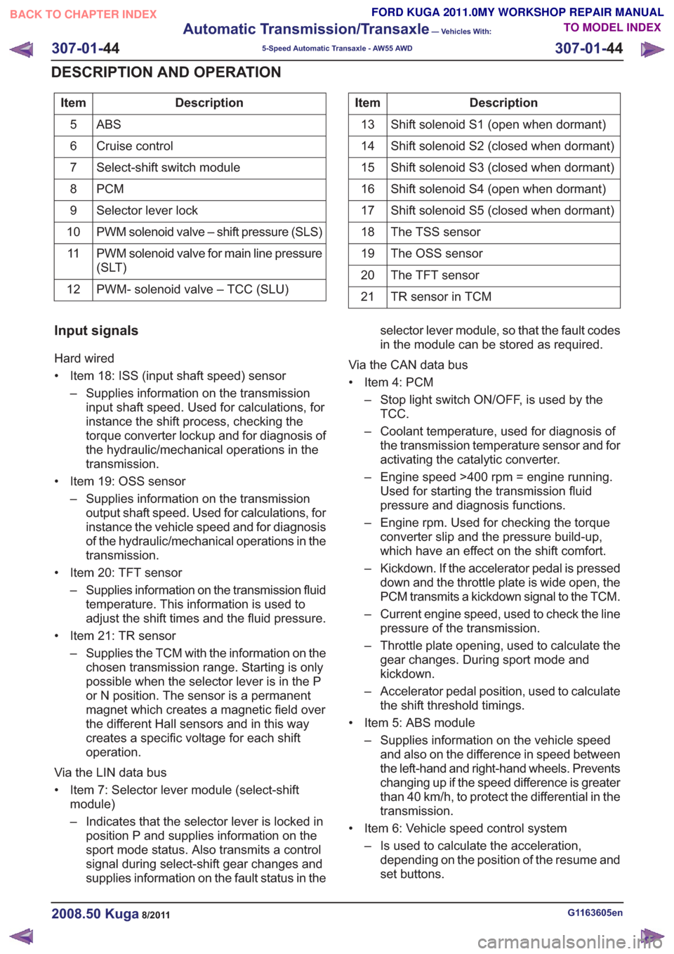
Description
Item
ABS5
Cruise control
6
Select-shift switch module
7
PCM
8
Selector lever lock
9
PWM solenoid valve – shift pressure (SLS)
10
PWM solenoid valve for main line pressure
(SLT)
11
PWM- solenoid valve – TCC (SLU)
12Description
Item
Shift solenoid S1 (open when dormant)
13
Shift solenoid S2 (closed when dormant)
14
Shift solenoid S3 (closed when dormant)
15
Shift solenoid S4 (open when dormant)
16
Shift solenoid S5 (closed when dormant)
17
The TSS sensor
18
The OSS sensor
19
The TFT sensor
20
TR sensor in TCM
21
Input signals
Hard wired
• Item 18: ISS (input shaft speed) sensor
– Supplies information on the transmissioninput shaft speed. Used for calculations, for
instance the shift process, checking the
torque converter lockup and for diagnosis of
the hydraulic/mechanical operations in the
transmission.
• Item 19: OSS sensor – Supplies information on the transmissionoutput shaft speed. Used for calculations, for
instance the vehicle speed and for diagnosis
of the hydraulic/mechanical operations in the
transmission.
• Item 20: TFT sensor – Supplies information on the transmission fluidtemperature. This information is used to
adjust the shift times and the fluid pressure.
• Item 21: TR sensor – Supplies the TCM with the information on thechosen transmission range. Starting is only
possible when the selector lever is in the P
or N position. The sensor is a permanent
magnet which creates a magnetic field over
the different Hall sensors and in this way
creates a specific voltage for each shift
operation.
Via the LIN data bus
• Item 7: Selector lever module (select-shift module)
– Indicates that the selector lever is locked inposition P and supplies information on the
sport mode status. Also transmits a control
signal during select-shift gear changes and
supplies information on the fault status in the selector lever module, so that the fault codes
in the module can be stored as required.
Via the CAN data bus
• Item 4: PCM – Stop light switch ON/OFF, is used by theTCC.
– Coolant temperature, used for diagnosis of the transmission temperature sensor and for
activating the catalytic converter.
– Engine speed >400 rpm = engine running. Used for starting the transmission fluid
pressure and diagnosis functions.
– Engine rpm. Used for checking the torque converter slip and the pressure build-up,
which have an effect on the shift comfort.
– Kickdown. If the accelerator pedal is pressed down and the throttle plate is wide open, the
PCM transmits a kickdown signal to the TCM.
– Current engine speed, used to check the line pressure of the transmission.
– Throttle plate opening, used to calculate the gear changes. During sport mode and
kickdown.
– Accelerator pedal position, used to calculate the shift threshold timings.
• Item 5: ABS module – Supplies information on the vehicle speedand also on the difference in speed between
the left-hand and right-hand wheels. Prevents
changing up if the speed difference is greater
than 40 km/h, to protect the differential in the
transmission.
• Item 6: Vehicle speed control system – Is used to calculate the acceleration,depending on the position of the resume and
set buttons.
G1163605en2008.50 Kuga8/2011
307-01- 44
Automatic Transmission/Transaxle
— Vehicles With:
5-Speed Automatic Transaxle - AW55 AWD
307-01- 44
DESCRIPTION AND OPERATION
TO MODEL INDEX
BACK TO CHAPTER INDEX
FORD KUGA 2011.0MY WORKSHOP REPAIR MANUAL