2011 FORD KUGA Diesel
[x] Cancel search: DieselPage 1525 of 2057
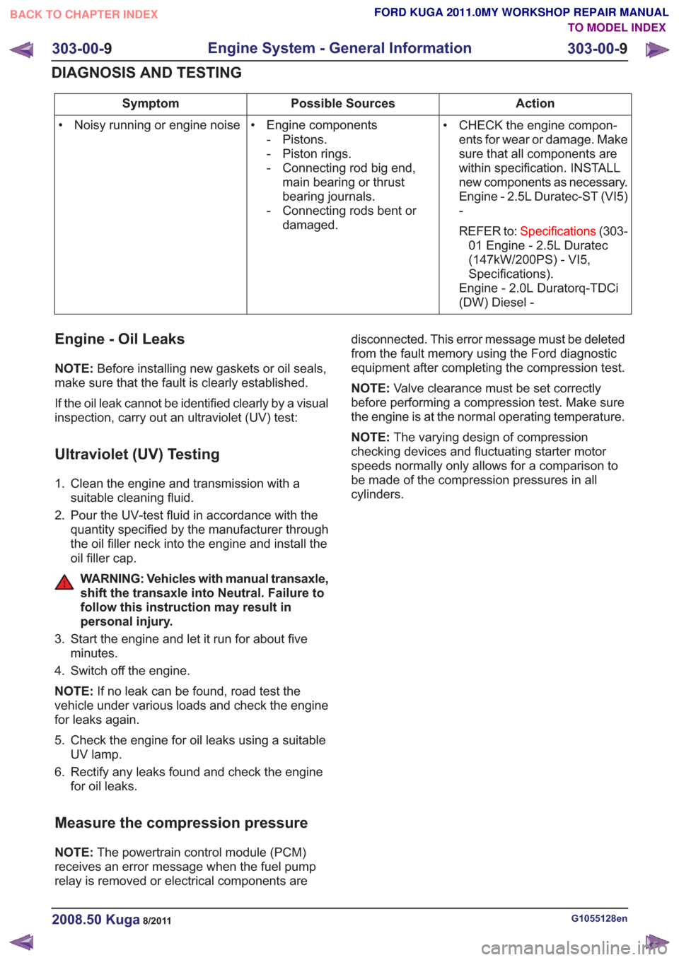
Action
Possible Sources
Symptom
• CHECK the engine compon-ents for wear or damage. Make
sure that all components are
within specification. INSTALL
new components as necessary.
Engine - 2.5L Duratec-ST (VI5)
-
REFER to: Specifications (303-
01 Engine - 2.5L Duratec
(147kW/200PS) - VI5,
Specifications).
Engine - 2.0L Duratorq-TDCi
(DW) Diesel -
• Engine components
- Pistons.
- Piston rings.
- Connecting rod big end,main bearing or thrust
bearing journals.
- Connecting rods bent or damaged.
• Noisy running or engine noise
Engine - Oil Leaks
NOTE:
Before installing new gaskets or oil seals,
make sure that the fault is clearly established.
If the oil leak cannot be identified clearly by a visual
inspection, carry out an ultraviolet (UV) test:
Ultraviolet (UV) Testing
1. Clean the engine and transmission with a suitable cleaning fluid.
2. Pour the UV-test fluid in accordance with the quantity specified by the manufacturer through
the oil filler neck into the engine and install the
oil filler cap.
WARNING: Vehicles with manual transaxle,
shift the transaxle into Neutral. Failure to
follow this instruction may result in
personal injury.
3. Start the engine and let it run for about five minutes.
4. Switch off the engine.
NOTE: If no leak can be found, road test the
vehicle under various loads and check the engine
for leaks again.
5. Check the engine for oil leaks using a suitable UV lamp.
6. Rectify any leaks found and check the engine for oil leaks.
Measure the compression pressure
NOTE: The powertrain control module (PCM)
receives an error message when the fuel pump
relay is removed or electrical components are disconnected. This error message must be deleted
from the fault memory using the Ford diagnostic
equipment after completing the compression test.
NOTE:
Valve clearance must be set correctly
before performing a compression test. Make sure
the engine is at the normal operating temperature.
NOTE: The varying design of compression
checking devices and fluctuating starter motor
speeds normally only allows for a comparison to
be made of the compression pressures in all
cylinders.
G1055128en2008.50 Kuga8/2011
303-00- 9
Engine System - General Information
303-00- 9
DIAGNOSIS AND TESTING
TO MODEL INDEX
BACK TO CHAPTER INDEX
FORD KUGA 2011.0MY WORKSHOP REPAIR MANUAL
Page 1527 of 2057
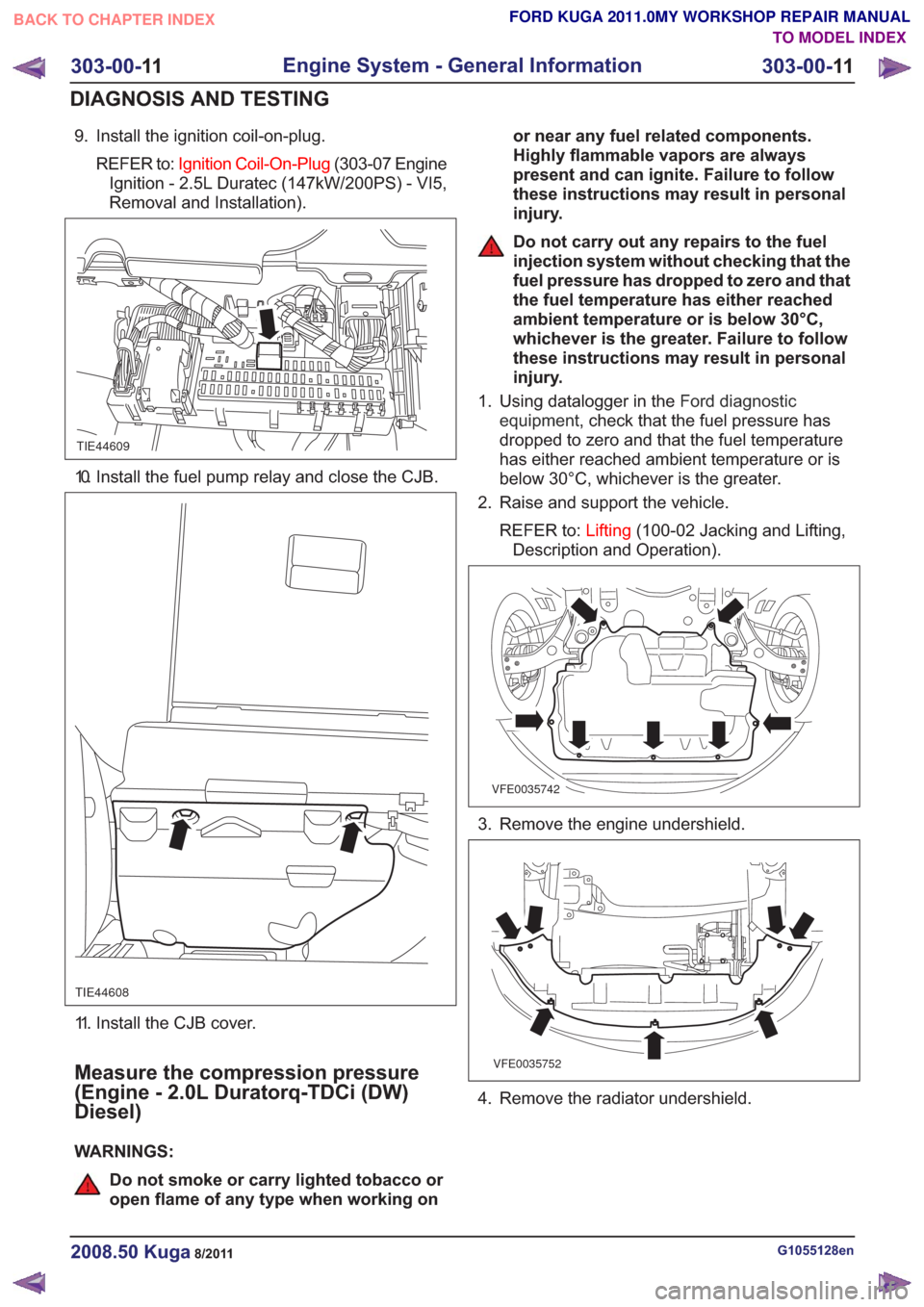
9. Install the ignition coil-on-plug.REFER to: Ignition Coil-On-Plug (303-07 Engine
Ignition - 2.5L Duratec (147kW/200PS) - VI5,
Removal and Installation).
TIE44609
10. Install the fuel pump relay and close the CJB.
TIE44608
11. Install the CJB cover.
Measure the compression pressure
(Engine - 2.0L Duratorq-TDCi (DW)
Diesel)
WARNINGS:
Do not smoke or carry lighted tobacco or
open flame of any type when working on or near any fuel related components.
Highly flammable vapors are always
present and can ignite. Failure to follow
these instructions may result in personal
injury.
Do not carry out any repairs to the fuel
injection system without checking that the
fuel pressure has dropped to zero and that
the fuel temperature has either reached
ambient temperature or is below 30°C,
whichever is the greater. Failure to follow
these instructions may result in personal
injury.
1. Using datalogger in the Ford diagnostic
equipment , check that the fuel pressure has
dropped to zero and that the fuel temperature
has either reached ambient temperature or is
below 30°C, whichever is the greater.
2. Raise and support the vehicle.
REFER to: Lifting(100-02 Jacking and Lifting,
Description and Operation).
VFE0035742
3. Remove the engine undershield.
VFE0035752
4. Remove the radiator undershield.
G1055128en2008.50 Kuga8/2011
303-00- 11
Engine System - General Information
303-00- 11
DIAGNOSIS AND TESTING
TO MODEL INDEX
BACK TO CHAPTER INDEX
FORD KUGA 2011.0MY WORKSHOP REPAIR MANUAL
Page 1532 of 2057
E65955
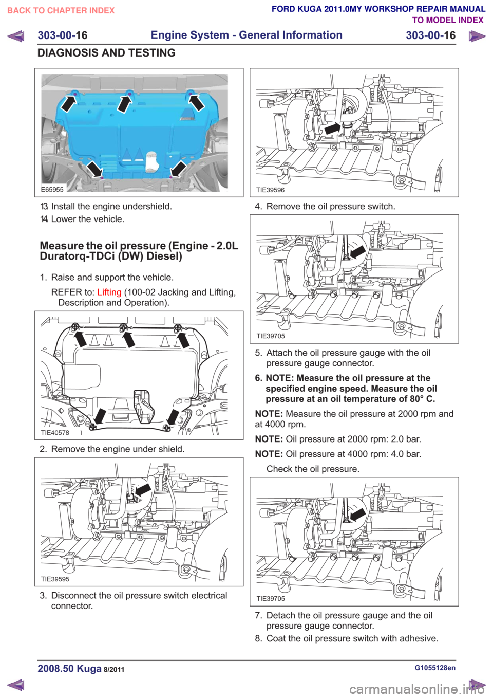
13. Install the engine undershield.
14. Lower the vehicle.
Measure the oil pressure (Engine - 2.0L
Duratorq-TDCi (DW) Diesel)
1. Raise and support the vehicle.REFER to: Lifting(100-02 Jacking and Lifting,
Description and Operation).
TIE40578
2. Remove the engine under shield.
TIE39595
3. Disconnect the oil pressure switch electrical connector.
TIE39596
4. Remove the oil pressure switch.
TIE39705
5. Attach the oil pressure gauge with the oilpressure gauge connector.
6. NOTE: Measure the oil pressure at the specified engine speed. Measure the oil
pressure at an oil temperature of 80° C.
NOTE: Measure the oil pressure at 2000 rpm and
at 4000 rpm.
NOTE: Oil pressure at 2000 rpm: 2.0 bar.
NOTE: Oil pressure at 4000 rpm: 4.0 bar.
Check the oil pressure.
TIE39705
7. Detach the oil pressure gauge and the oil pressure gauge connector.
8. Coat the oil pressure switch with adhesive.
G1055128en2008.50 Kuga8/2011
303-00-16
Engine System - General Information
303-00- 16
DIAGNOSIS AND TESTING
TO MODEL INDEX
BACK TO CHAPTER INDEX
FORD KUGA 2011.0MY WORKSHOP REPAIR MANUAL
Page 1986 of 2057
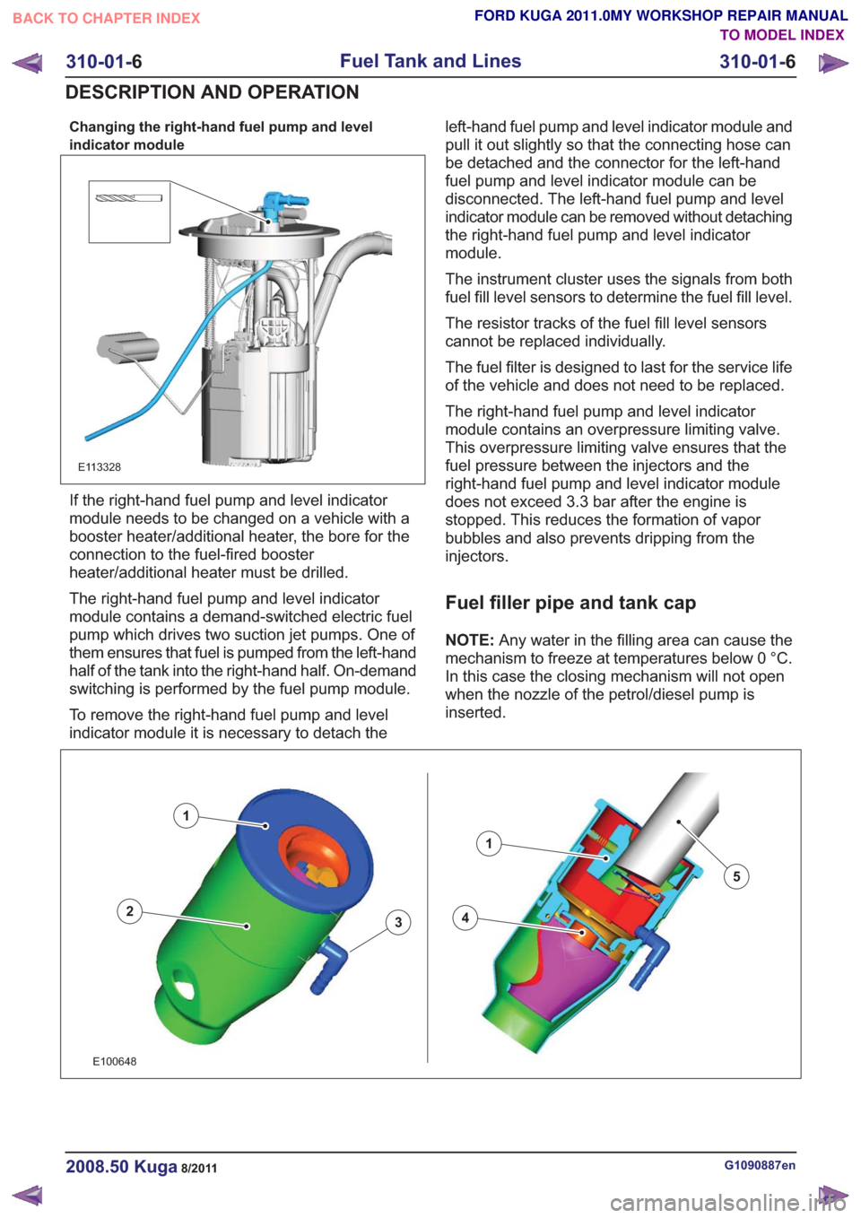
Changing the right-hand fuel pump and level
indicator module
E113328
If the right-hand fuel pump and level indicator
module needs to be changed on a vehicle with a
booster heater/additional heater, the bore for the
connection to the fuel-fired booster
heater/additional heater must be drilled.
The right-hand fuel pump and level indicator
module contains a demand-switched electric fuel
pump which drives two suction jet pumps. One of
them ensures that fuel is pumped from the left-hand
half of the tank into the right-hand half. On-demand
switching is performed by the fuel pump module.
To remove the right-hand fuel pump and level
indicator module it is necessary to detach theleft-hand fuel pump and level indicator module and
pull it out slightly so that the connecting hose can
be detached and the connector for the left-hand
fuel pump and level indicator module can be
disconnected. The left-hand fuel pump and level
indicator module can be removed without detaching
the right-hand fuel pump and level indicator
module.
The instrument cluster uses the signals from both
fuel fill level sensors to determine the fuel fill level.
The resistor tracks of the fuel fill level sensors
cannot be replaced individually.
The fuel filter is designed to last for the service life
of the vehicle and does not need to be replaced.
The right-hand fuel pump and level indicator
module contains an overpressure limiting valve.
This overpressure limiting valve ensures that the
fuel pressure between the injectors and the
right-hand fuel pump and level indicator module
does not exceed 3.3 bar after the engine is
stopped. This reduces the formation of vapor
bubbles and also prevents dripping from the
injectors.
Fuel filler pipe and tank cap
NOTE:
Any water in the filling area can cause the
mechanism to freeze at temperatures below 0 °C.
In this case the closing mechanism will not open
when the nozzle of the petrol/diesel pump is
inserted.
43
1
2
1
5
43
1
2
1
5
E100648
G1090887en2008.50 Kuga8/2011
310-01- 6
Fuel Tank and Lines
310-01- 6
DESCRIPTION AND OPERATION
TO MODEL INDEX
BACK TO CHAPTER INDEX
FORD KUGA 2011.0MY WORKSHOP REPAIR MANUAL
Page 2025 of 2057
Electronic Leak Detection
1.Refer to: Air Conditioning (A/C) System Health
and Safety Precautions (100-00 General
Information, Description and Operation).
2. WARNINGS:
Before starting leak detection, make
sure that the area where it is to be done
is well ventilated. If the surrounding air
is contaminated with refrigerant gas, the
leak detector will indicate this gas all
the time. Odors from other chemicals
such as antifreeze, diesel fuel, disc
brake cleaner, or other cleaning
solvents can cause the same problem.
Prevent air movement while performing
leak detection.
The refrigerant identification equipment
must be used before attaching the
manifold gauge set. Otherwise the
manifold gauge set may become
contaminated. Contaminated refrigerant
must be disposed of as special waste.
Follow the manufacturer's instructions
when working with the service unit.
NOTE: At 24°C with the engine switched off,
both manifold gauges should show 4.1 to 5.5
bar.
Attach the manifold gauge set to the service
gauge port valves.
3. For the leak test, close the manual valves on
the gauge set.
4. If little or no pressure is indicated, charge the
system with approx. 300g of refrigerant. Refer
to: Air Conditioning System - Evacuate and
Refill.
5. Use the R-134a Automatic Calibration Halogen
Leak Detector to leak test the refrigerant system.
Follow the instructions included with leak
detector for handling and operation techniques.
6. If any leak is found, extract the refrigerant under
suction. Refer to: Air Conditioning System -
Evacuate and Refill.
G549836en2008.50 Kuga8/2011
412-00- 14
Climate Control System - General Information
412-00- 14
GENERAL PROCEDURES
TO MODEL INDEX
BACK TO CHAPTER INDEX
FORD KUGA 2011.0MY WORKSHOP REPAIR MANUAL