2011 FORD KUGA injectors
[x] Cancel search: injectorsPage 1711 of 2057
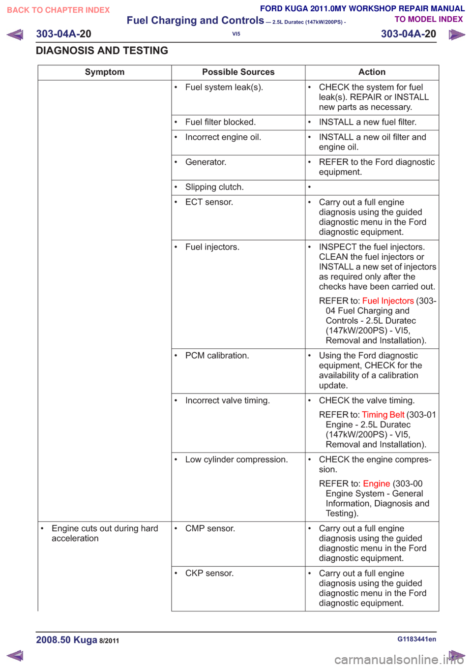
Action
Possible Sources
Symptom
• CHECK the system for fuelleak(s). REPAIR or INSTALL
new parts as necessary.
• Fuel system leak(s).
• INSTALL a new fuel filter.
• Fuel filter blocked.
• INSTALL a new oil filter andengine oil.
• Incorrect engine oil.
• REFER to the Ford diagnosticequipment.
• Generator.
•
• Slipping clutch.
• Carry out a full enginediagnosis using the guided
diagnostic menu in the Ford
diagnostic equipment.
• ECT sensor.
• INSPECT the fuel injectors.CLEAN the fuel injectors or
INSTALL a new set of injectors
as required only after the
checks have been carried out.
REFER to: Fuel Injectors (303-
04 Fuel Charging and
Controls - 2.5L Duratec
(147kW/200PS) - VI5,
Removal and Installation).
• Fuel injectors.
• Using the Ford diagnosticequipment, CHECK for the
availability of a calibration
update.
• PCM calibration.
• CHECK the valve timing.REFER to: Timing Belt (303-01
Engine - 2.5L Duratec
(147kW/200PS) - VI5,
Removal and Installation).
• Incorrect valve timing.
• CHECK the engine compres-sion.
REFER to: Engine(303-00
Engine System - General
Information, Diagnosis and
Testing).
• Low cylinder compression.
• Carry out a full enginediagnosis using the guided
diagnostic menu in the Ford
diagnostic equipment.
• CMP sensor.
• Engine cuts out during hard
acceleration
• Carry out a full enginediagnosis using the guided
diagnostic menu in the Ford
diagnostic equipment.
• CKP sensor.
G1183441en2008.50 Kuga8/2011
303-04A-
20
Fuel Charging and Controls
— 2.5L Duratec (147kW/200PS) -
VI5
303-04A- 20
DIAGNOSIS AND TESTING
TO MODEL INDEX
BACK TO CHAPTER INDEX
FORD KUGA 2011.0MY WORKSHOP REPAIR MANUAL
Page 1713 of 2057
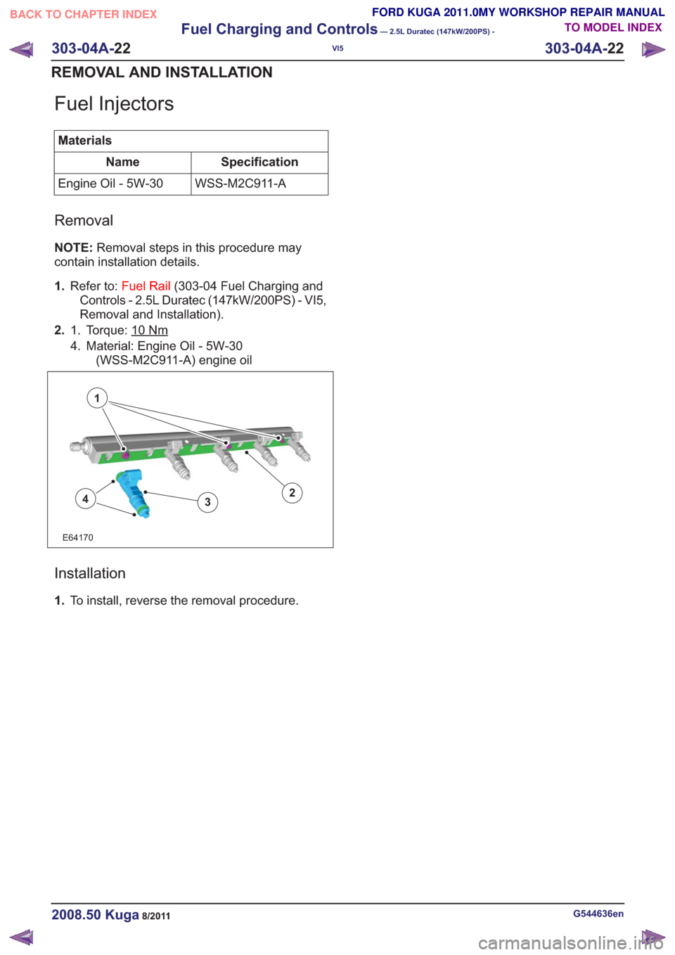
Fuel Injectors
MaterialsSpecification
Name
WSS-M2C911-A
Engine Oil - 5W-30
Removal
NOTE: Removal steps in this procedure may
contain installation details.
1. Refer to: Fuel Rail (303-04 Fuel Charging and
Controls - 2.5L Duratec (147kW/200PS) - VI5,
Removal and Installation).
2. Torque: 10
Nm1.
4. Material: Engine Oil - 5W-30
(WSS-M2C911-A) engine oil
E64170
1
243
Installation
1.To install, reverse the removal procedure.
G544636en2008.50 Kuga8/2011
303-04A- 22
Fuel Charging and Controls
— 2.5L Duratec (147kW/200PS) -
VI5
303-04A- 22
REMOVAL AND INSTALLATION
TO MODEL INDEX
BACK TO CHAPTER INDEX
FORD KUGA 2011.0MY WORKSHOP REPAIR MANUAL
Page 1775 of 2057
SECTION 303-14 Electronic Engine Controls— 2.5L Duratec
(147kW/200PS) - VI5
VEHICLE APPLICATION: 2008.50 Kuga
PA G E
CONTENTS
DESCRIPTION AND OPERATION
303-14-3
Electronic Engine Controls (Component Location) .............................................................
303-14-7
Electronic Engine Controls (Overview) ........................................................................\
.......
303-14-7
General overview ........................................................................\
........................................
303-14-8
Powertrain Control Module (PCM) ........................................................................\
..............
303-14-8
Knock Sensor ........................................................................\
.............................................
303-14-8
Camshaft Position (CMP) Sensor ........................................................................\
...............
303-14-9
Crankshaft Position (CKP) sensor ........................................................................\
..............
303-14-9
Camshaft adjuster solenoid valve........................................................................\
...............
303-14-9
Manifold absolute pressure and temperature sensor .........................................................
303-14-9
Accelerator pedal position (APP) sensor ........................................................................\
....
303-14-10
Throttle control unit ........................................................................\
.....................................
303-14-10
Engine Coolant Temperature (ECT) sensor.......................................................................
303-14-10
Ignition coil-on-plug ........................................................................\
....................................
303-14-12
Electronic Engine Controls (System Operation and Component Description) ...................
303-14-12
System Diagram ........................................................................\
.........................................
303-14-16
System Operation ........................................................................\
.......................................
303-14-18
Speed and TDC recording ........................................................................\
......................
303-14-19
Calculation of the ignition angle ........................................................................\
..............
303-14-20
Engine fueling ........................................................................\
.........................................
303-14-22
Engine speed control ........................................................................\
..............................
303-14-22
Oil monitoring ........................................................................\
..........................................
303-14-23
Calculation of valve timing adjustment angle..................................................................
303-14-23
Boost pressure control ........................................................................\
............................
303-14-24
Starting process ........................................................................\
......................................
303-14-24
Alternator control (Smart Charge) ........................................................................\
...........
303-14-24
Component Description ........................................................................\
..............................
303-14-24
CKP sensor ........................................................................\
.............................................
303-14-25
Broadband HO2S ........................................................................\
...................................
303-14-26
VCT (variable camshaft timing) solenoids ......................................................................
303-14-27
MAF sensor ........................................................................\
.............................................
303-14-28
APP sensor ........................................................................\
.............................................
303-14-29
CPP sensor ........................................................................\
.............................................
303-14-29
BPP switches ........................................................................\
..........................................
303-14-30
Air conditioning (A/C) pressure sensor ........................................................................\
...
303-14-30
Throttle
control unit ........................................................................\
.................................
303-14-31
ECT sensor ........................................................................\
.............................................
303-14-31
Cooling fan module ........................................................................\
.................................
303-14-32
injectors........................................................................\
...................................................
303-14-32
Ignition coil-on-plug ........................................................................\
.................................
303-14-33
Fuel pressure/fuel temperature sensor ........................................................................\
...
303-14-33
Wastegate control valve ........................................................................\
..........................
303-14-34
Engine oil level, temperature and quality sensor ............................................................
303-14-1
Electronic Engine Controls— 2.5L Duratec (147kW/200PS) - VI5303-14-
1
.
TO MODEL INDEX
BACK TO CHAPTER INDEX
PAGE 1 OF 2
FORD KUGA 2011.0MY WORKSHOP REPAIR MANUAL
Page 1777 of 2057
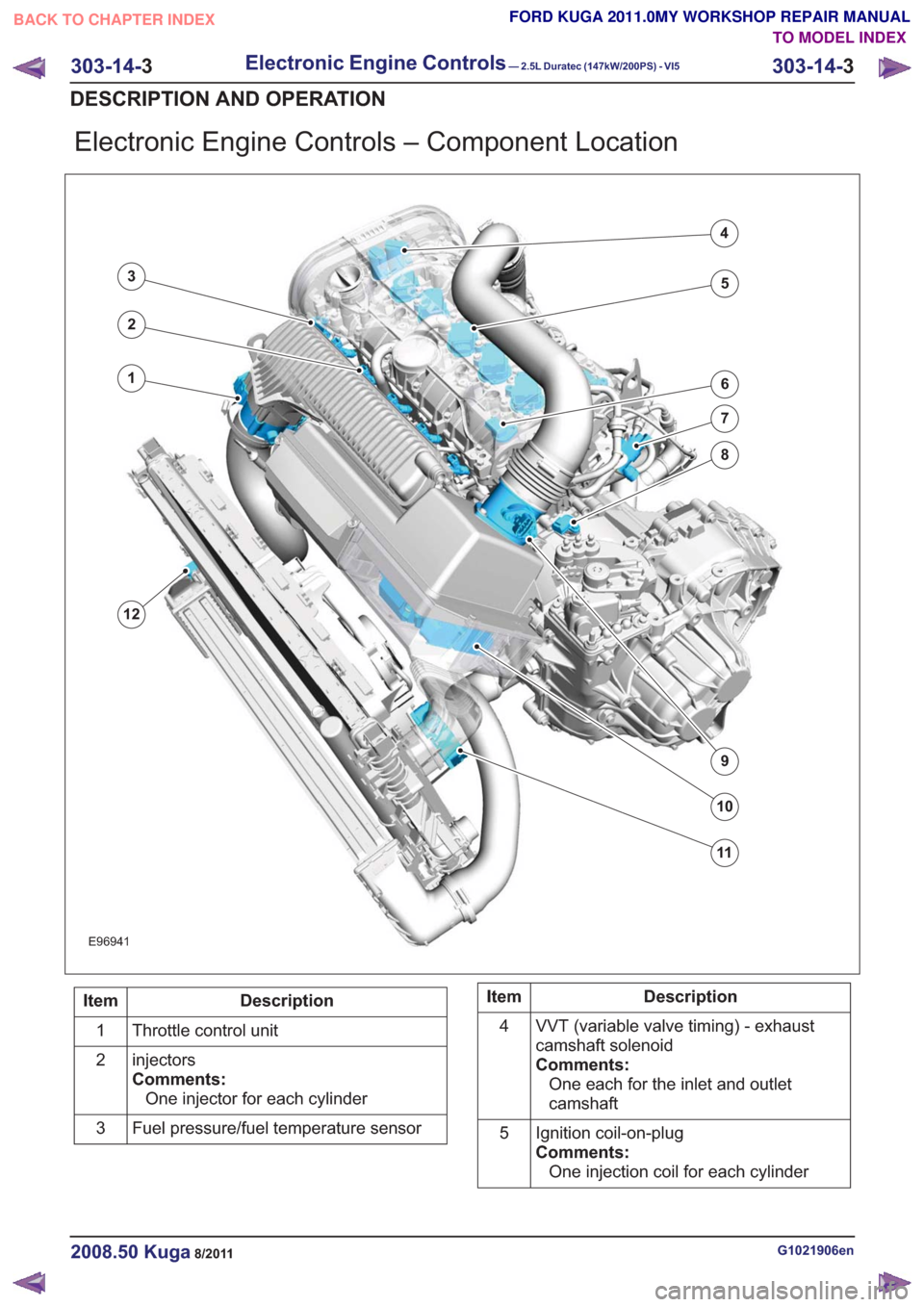
Electronic Engine Controls – Component Location
E96941
1
12
2
3
4
5
6
7
8
9
10
11
Description
Item
Throttle control unit
1
injectors
Comments:One injector for each cylinder
2
Fuel pressure/fuel temperature sensor
3Description
Item
VVT (variable valve timing) - exhaust
camshaft solenoid
Comments:One each for the inlet and outlet
camshaft
4
Ignition coil-on-plug
Comments:One injection coil for each cylinder
5
G1021906en2008.50 Kuga8/2011
303-14-
3
Electronic Engine Controls— 2.5L Duratec (147kW/200PS) - VI5303-14-
3
DESCRIPTION AND OPERATION
TO MODEL INDEX
BACK TO CHAPTER INDEX
FORD KUGA 2011.0MY WORKSHOP REPAIR MANUAL
Page 1790 of 2057
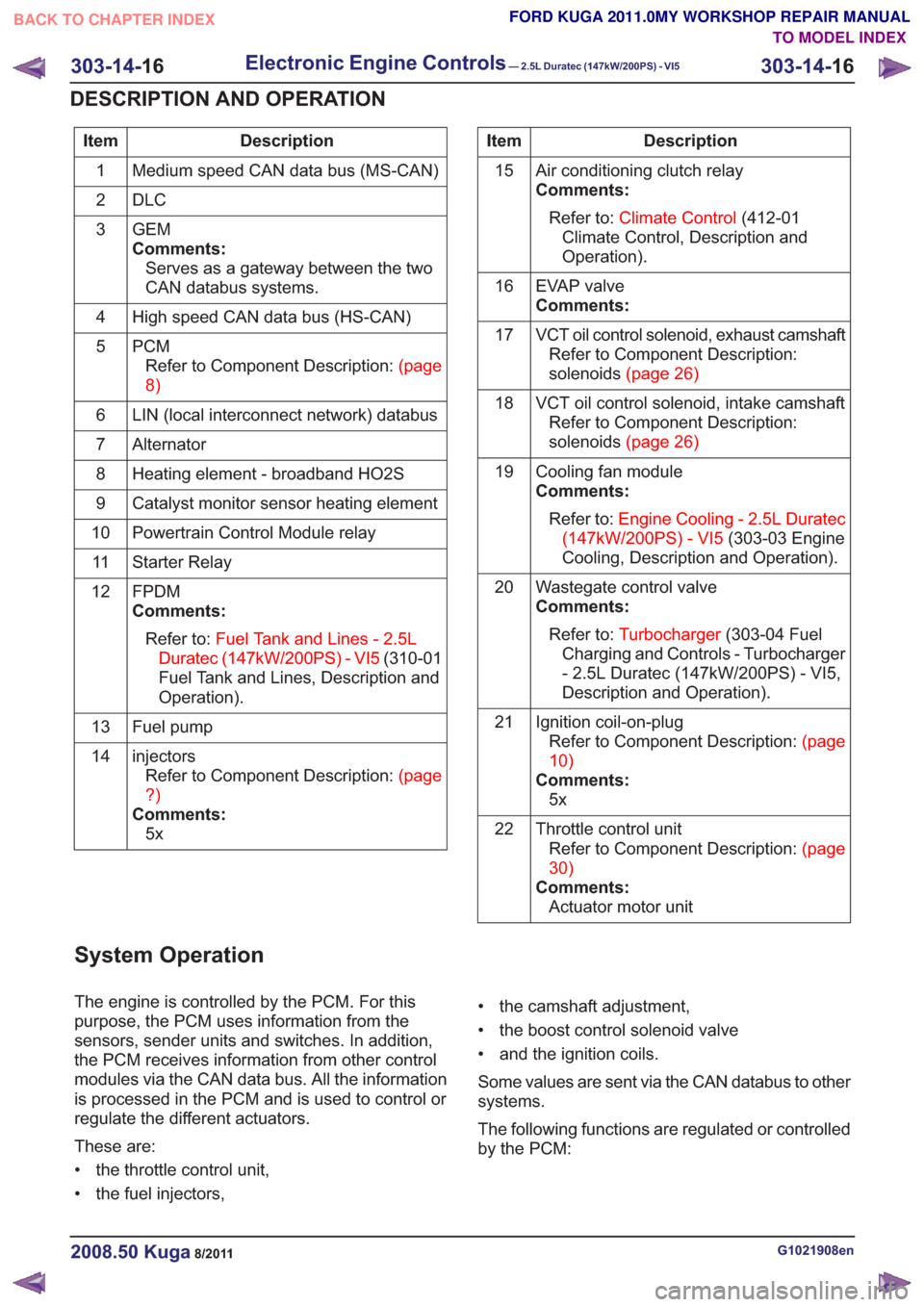
Description
Item
Medium speed CAN data bus (MS-CAN)
1
DLC
2
GEM
Comments:Serves as a gateway between the two
CAN databus systems.
3
High speed CAN data bus (HS-CAN)
4
PCMRefertoComponentDescription:(page
8)
5
LIN (local interconnect network) databus
6
Alternator
7
Heating element - broadband HO2S
8
Catalyst monitor sensor heating element
9
Powertrain Control Module relay
10
Starter Relay
11
FPDM
Comments:Refer to: Fuel Tank and Lines - 2.5L
Duratec (147kW/200PS) - VI5 (310-01
Fuel Tank and Lines, Description and
Operation).
12
Fuel pump
13
injectorsRefertoComponentDescription:(page
?)
Comments: 5x
14Description
Item
Air conditioning clutch relay
Comments:Refer to: Climate Control (412-01
Climate Control, Description and
Operation).
15
EVAP valve
Comments:
16
VCT oil control solenoid, exhaust camshaftRefer to Component Description:
solenoids(page26)
17
VCT oil control solenoid, intake camshaftRefer to Component Description:
solenoids(page26)
18
Cooling fan module
Comments:Refer to: Engine Cooling - 2.5L Duratec
(147kW/200PS) - VI5 (303-03 Engine
Cooling, Description and Operation).
19
Wastegate control valve
Comments:Refer to: Turbocharger (303-04 Fuel
Charging and Controls - Turbocharger
- 2.5L Duratec (147kW/200PS) - VI5,
Description and Operation).
20
Ignition coil-on-plugRefertoComponentDescription:(page
10)
Comments: 5x
21
Throttle control unitRefertoComponentDescription:(page
30)
Comments: Actuator motor unit
22
System Operation
The engine is controlled by the PCM. For this
purpose, the PCM uses information from the
sensors, sender units and switches. In addition,
the PCM receives information from other control
modules via the CAN data bus. All the information
is processed in the PCM and is used to control or
regulate the different actuators.
These are:
• the throttle control unit,
• the fuel injectors, • the camshaft adjustment,
• the boost control solenoid valve
• and the ignition coils.
Some values are sent via the CAN databus to other
systems.
The following functions are regulated or controlled
by the PCM:
G1021908en2008.50 Kuga8/2011
303-14-
16
Electronic Engine Controls— 2.5L Duratec (147kW/200PS) - VI5303-14-
16
DESCRIPTION AND OPERATION
TO MODEL INDEX
BACK TO CHAPTER INDEX
FORD KUGA 2011.0MY WORKSHOP REPAIR MANUAL
Page 1791 of 2057
• Starting process
• Engine running– Fuel supply to the engine including lambdacontrol
– Ignition setting including knock control
– Idle speed control
– Boost pressure control
– Valve timing via the camshaft adjuster for the intake and exhaust camshafts (including
internal exhaust gas recirculation)
• Refrigerant compressor (activation, deactivation and delivery)
• EVAP purge valve
• Charging system
Fuel is supplied to the engine via a sequential
multi-point injection system. Ignition is performed
by a distributor-less ignition system with one
ignition coil unit for each cylinder.
The PCM optimizes engine power and emissions
at all times by processing the sensor signals and
information received via the CAN databus and
using these for open or closed loop control of the
different variables.
The PCM contains part of the PATS (passive
anti-theft system).
The PCM is supplied with battery voltage via a fuse
in the BJB (battery junction box). This power supply
is needed to ensure that saved data is not lost
when the engine is switched off.
For other power supply requirements, the PCM
switches on a relay in the BJB which is responsible
for supplying power to the PCM and to some
sensors and actuators. Each of these are protected
by fuses in the BJB.
To guarantee optimum engine running at all times,
the PCM has several adaptive (self-learning)
functions. These adapt the output signals to
changing circumstances, such as wear or system
faults.
In some cases a faulty signal is replaced with a
substitute value or limited. A substitute value can
be calculated from other signals or it can be
predefined by the PCM. The substitute value allows
the vehicle to keep on running without the emission
values changing unduly. Depending on the signal
failure, the PCM operates in emergency mode. In
this mode, the engine power and/or the engine
speed is reduced to prevent further damage.
Depending on the faulty signal, a fault code is
stored in the error memory of the PCM. These can be read out using IDS (Integrated Diagnostic
System) via the DLC.
The PCM processes and evaluates the signals
from the sensors. The following sensors send
signals to the PCM:
• CMP sensors
• CKP sensor
• MAF sensor
•KS
• ECT sensor
• TP sensor
• APP sensor
• Broadband HO2S
• Catalyst monitor sensor
• MAPT sensor
• Air conditioning (A/C) pressure sensor
• Alternator
• Fuel temperature and fuel pressure sensor
• Engine oil level, temperature and quality sensor
• Outside air temperature sensor
The following components receive signals from the
PCM:
• Powertrain Control Module relay
• A/C clutch relay
• injectors
• Direct ignition coils
• Cooling fan module
• Throttle control unit
• Camshaft adjuster solenoid valve
• Starter Relay
• EVAP purge valve
• Alternator
• Heating element - broadband HO2S
• Catalyst monitor sensor heating element
• FPDM
• Wastegate control valve
• Air conditioning compressor
The PCM receives the following signals via the
CAN databus:
• APP
•CPP
• BPP
• Vehicle speed.
• Refrigerant compressor request
• PAT S
G1021908en2008.50 Kuga8/2011
303-14-
17
Electronic Engine Controls— 2.5L Duratec (147kW/200PS) - VI5303-14-
17
DESCRIPTION AND OPERATION
TO MODEL INDEX
BACK TO CHAPTER INDEX
FORD KUGA 2011.0MY WORKSHOP REPAIR MANUAL
Page 1794 of 2057
than to a change in the throttle valve position. The
ignition timing also changes much more quickly.
To keep the ignition point as close as possible to
the knock limit and so optimize the efficiency of the
engine, two KS are installed in the engine, which
pick up the mechanical vibrations of the engine
and convert them into an electrical signal for the
PCM.
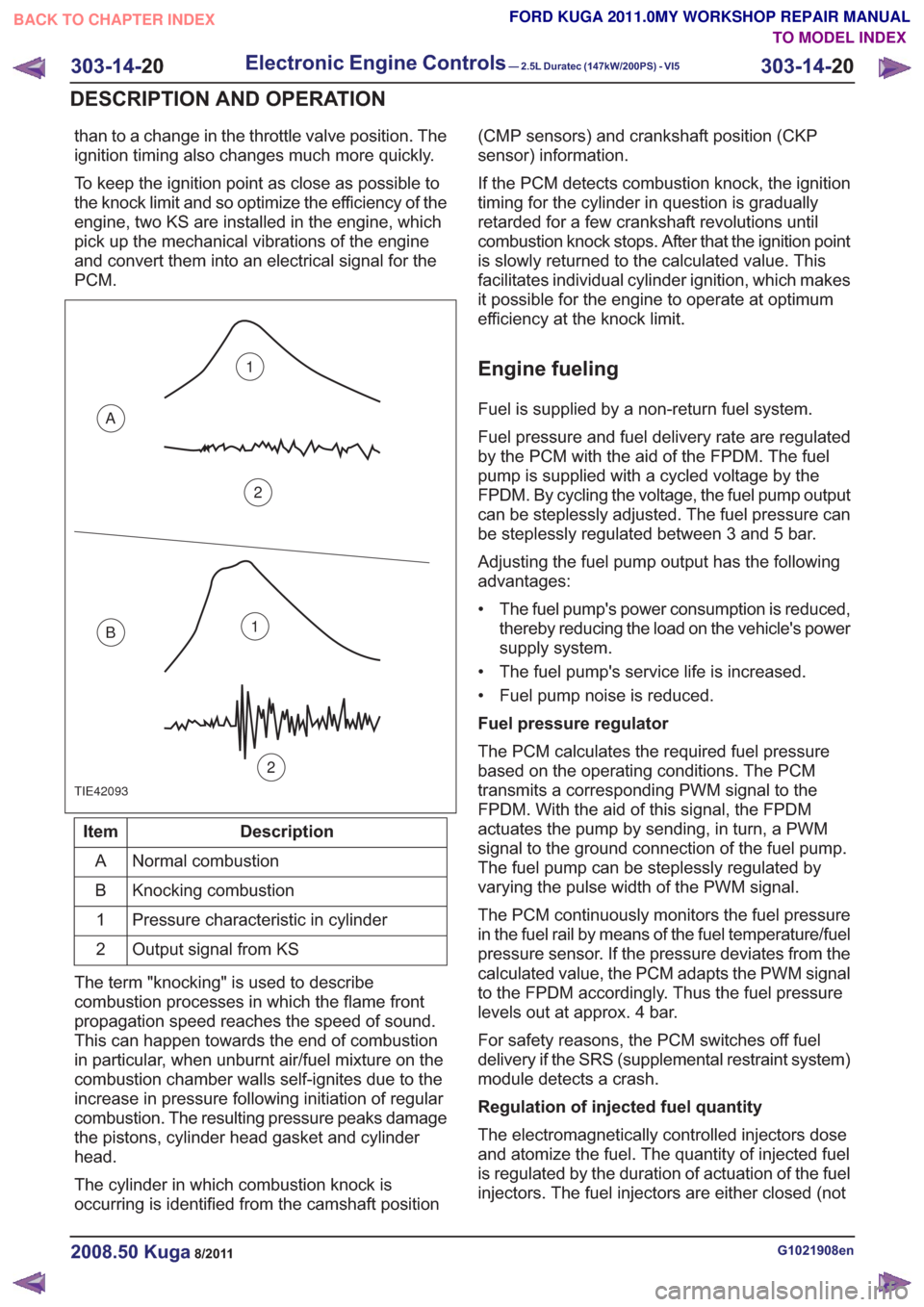
TIE42093
1
2
A
B1
2
Description
Item
Normal combustion
A
Knocking combustion
B
Pressure characteristic in cylinder
1
Output signal from KS
2
The term "knocking" is used to describe
combustion processes in which the flame front
propagation speed reaches the speed of sound.
This can happen towards the end of combustion
in particular, when unburnt air/fuel mixture on the
combustion chamber walls self-ignites due to the
increase in pressure following initiation of regular
combustion. The resulting pressure peaks damage
the pistons, cylinder head gasket and cylinder
head.
The cylinder in which combustion knock is
occurring is identified from the camshaft position (CMP sensors) and crankshaft position (CKP
sensor) information.
If the PCM detects combustion knock, the ignition
timing for the cylinder in question is gradually
retarded for a few crankshaft revolutions until
combustion knock stops. After that the ignition point
is slowly returned to the calculated value. This
facilitates individual cylinder ignition, which makes
it possible for the engine to operate at optimum
efficiency at the knock limit.
Engine fueling
Fuel is supplied by a non-return fuel system.
Fuel pressure and fuel delivery rate are regulated
by the PCM with the aid of the FPDM. The fuel
pump is supplied with a cycled voltage by the
FPDM. By cycling the voltage, the fuel pump output
can be steplessly adjusted. The fuel pressure can
be steplessly regulated between 3 and 5 bar.
Adjusting the fuel pump output has the following
advantages:
• The fuel pump's power consumption is reduced,
thereby reducing the load on the vehicle's power
supply system.
• The fuel pump's service life is increased.
• Fuel pump noise is reduced.
Fuel pressure regulator
The PCM calculates the required fuel pressure
based on the operating conditions. The PCM
transmits a corresponding PWM signal to the
FPDM. With the aid of this signal, the FPDM
actuates the pump by sending, in turn, a PWM
signal to the ground connection of the fuel pump.
The fuel pump can be steplessly regulated by
varying the pulse width of the PWM signal.
The PCM continuously monitors the fuel pressure
in the fuel rail by means of the fuel temperature/fuel
pressure sensor. If the pressure deviates from the
calculated value, the PCM adapts the PWM signal
to the FPDM accordingly. Thus the fuel pressure
levels out at approx. 4 bar.
For safety reasons, the PCM switches off fuel
delivery if the SRS (supplemental restraint system)
module detects a crash.
Regulation of injected fuel quantity
The electromagnetically controlled injectors dose
and atomize the fuel. The quantity of injected fuel
is regulated by the duration of actuation of the fuel
injectors. The fuel injectors are either closed (not
G1021908en2008.50 Kuga8/2011
303-14- 20
Electronic Engine Controls— 2.5L Duratec (147kW/200PS) - VI5303-14-
20
DESCRIPTION AND OPERATION
TO MODEL INDEX
BACK TO CHAPTER INDEX
FORD KUGA 2011.0MY WORKSHOP REPAIR MANUAL
Page 1795 of 2057
actuated) or opened (actuated). Each cylinder has
its own injector. The injection is accurately dosed
and takes place at a time determined by the PCM.
Injection takes place immediately in front of the
intake valves of the cylinder. The injectors are
actuated ground side via end-stages integrated
into the PCM and using the signal calculated by
the engine management system. Power is supplied
via the Powertrain Control Module relay in the BJB.
The injected fuel quantity depends on the opening
time, the fuel pressure and the diameter of the
nozzle holes.
The fuel metering is determined via open or
closed-loop control.
The open control loop differs from the closed
control loop in that the lambda control is
deactivated.
The PCM switches from closed to open-loop control
if the HO2S cools down to below 600°C or fails, as
well as when accelerating, coasting and at full load.
Regulation of injected fuel quantity via the PCM
involves:
• controlling the fuel pump,
• calculating the required quantity of fuel forengine starting,
• observance of the desired air/fuel ratio,
• calculating air mass,
• and calculating the fuel quantity for the different operating states and corresponding fuel
adjustment measures.
Open loop control
Open loop control is used primarily for fuel
injection, as long as the signals of the HO2S are
not involved in the calculation of the PCM.
The two most important reasons that make it
absolutely essential to run the engine without
lambda control (open-loop control) are the following
operating conditions:
• Cold engine (starting, warm-up phase)
• Full-load operation (WOT (wide open throttle))
Under these operating conditions the engine needs
a rich air/fuel mixture with lambda values below λ
= 1 in order to achieve optimum running or
optimum performance.
It is possible to keep this unregulated range very
small by using a broadband HO2S.
Closed-loop control
Closed loop control ensures strict control of
exhaust emissions in conjunction with the TWC (three-way catalytic converter) and economical fuel
consumption. With closed loop control, the signals
from the HO2S are analyzed by the PCM and the
engine always runs in the optimum range of λ = 1.
In addition to the normal HO2S, the signal from the
monitoring sensor for the catalytic converter is also
included in the control. The lambda control is
optimized on the basis of this data.
Certain factors such as wear, component
tolerances or more minor defects such as air leaks
in the intake system are compensated for by
lambda control. If the deviation occurs for a longer
period of time, this is recorded by the adaptive
(self-learning) function of lambda control. In this
instance, the entire map is shifted by the
corresponding amount, to enable control to
commence once again from the virtual baseline.
These adaptive settings are stored in the PCM and
are also used in open-loop control conditions.
If the adaptive value is too high or too low, an error
is stored in the fault memory of the PCM.
Oxygen sensor (HO2S) and catalyst monitor
sensor
A broadband HO2S is used as the HO2S. The
HO2S is located in front of the TWC. The catalyst
monitor sensor is located in the center of the TWC
so that it can detect any deterioration in the
cleaning performance of the TWC more quickly.
The HO2S measures the residual amount of
oxygen in the exhaust before the TWC.
The catalyst monitor sensor measures the amount
of oxygen in the exhaust gas after or in the TWC.
Both the HO2S and the catalyst monitor sensor
transmit these data to the PCM.
The broadband HO2S works at temperatures of
between 650°C and 900 °C. If the temperature
rises above 1000°C, the oxygen sensor will be
irreparably damaged.
To reach optimum operating temperature as quickly
as possible, an electrically-heated oxygen sensor
is installed. The heating also serves to maintain a
suitable operating temperature while coasting, for
example, when no hot gases are flowing past the
oxygen sensor.
The heating element in the HO2S is a PTC
(positive temperature coefficient) resistor. The
heating element is supplied with battery voltage as
soon as the Powertrain Control Module relay
engages. The HO2S is earthed via the PCM. As
the heating current is high when the element is
cold, it is limited via PWM in the PCM until a certain
G1021908en2008.50 Kuga8/2011
303-14-
21
Electronic Engine Controls— 2.5L Duratec (147kW/200PS) - VI5303-14-
21
DESCRIPTION AND OPERATION
TO MODEL INDEX
BACK TO CHAPTER INDEX
FORD KUGA 2011.0MY WORKSHOP REPAIR MANUAL