Starting process
The PCM enables the starting process when a key
providing a valid code is read via the PATS.
Refer to:Starting System (303-06 Starting System
- 2.5L Duratec (147kW/200PS) - VI5, Description
and Operation).
Alternator control (Smart Charge)
The vehicle is fitted with a Smart Charging charge
system.
In this system, the charge voltage is regulated by
the PCM.
Refer to: Generator (414-02 Generator and
Regulator, Description and Operation).
Component Description
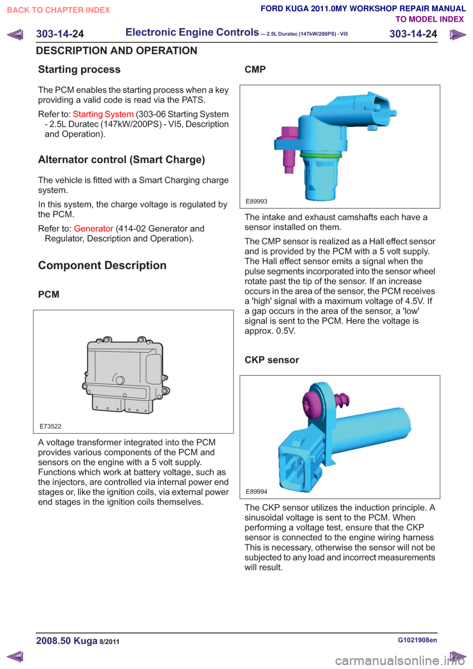
PCM
E73522
A voltage transformer integrated into the PCM
provides various components of the PCM and
sensors on the engine with a 5 volt supply.
Functions which work at battery voltage, such as
the injectors, are controlled via internal power end
stages or, like the ignition coils, via external power
end stages in the ignition coils themselves.
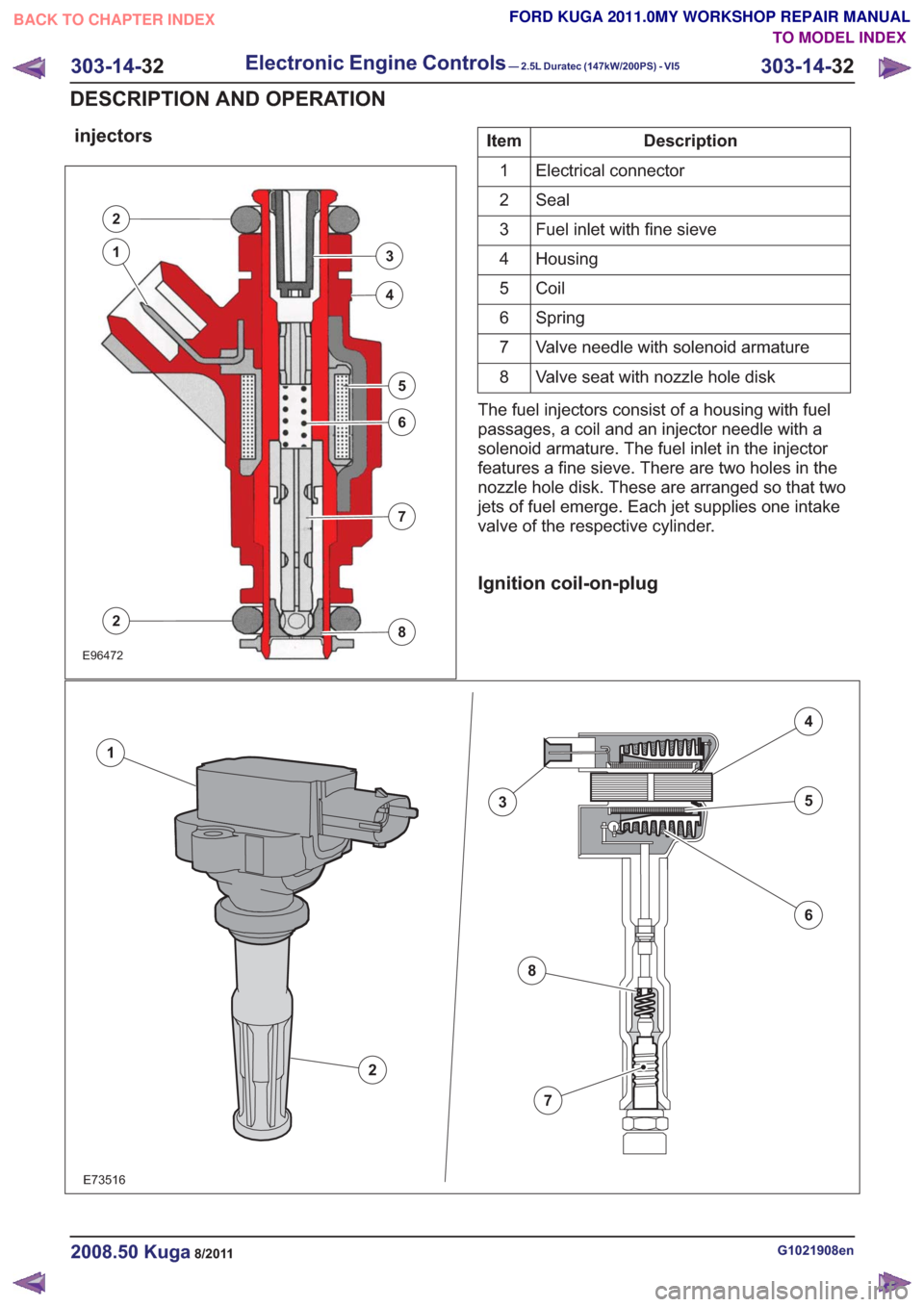
CMP
E89993
The intake and exhaust camshafts each have a
sensor installed on them.
The CMP sensor is realized as a Hall effect sensor
and is provided by the PCM with a 5 volt supply.
The Hall effect sensor emits a signal when the
pulse segments incorporated into the sensor wheel
rotate past the tip of the sensor. If an increase
occurs in the area of the sensor, the PCM receives
a 'high' signal with a maximum voltage of 4.5V. If
a gap occurs in the area of the sensor, a 'low'
signal is sent to the PCM. Here the voltage is
approx. 0.5V.
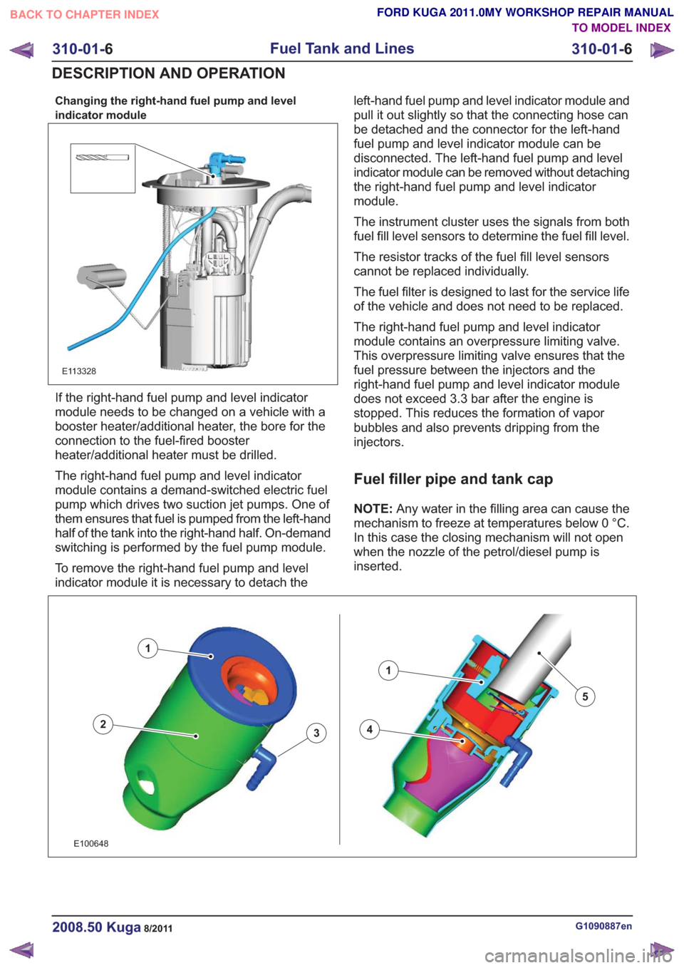
CKP sensor
E89994
The CKP sensor utilizes the induction principle. A
sinusoidal voltage is sent to the PCM. When
performing a voltage test, ensure that the CKP
sensor is connected to the engine wiring harness
This is necessary, otherwise the sensor will not be
subjected to any load and incorrect measurements
will result.
G1021908en2008.50 Kuga8/2011
303-14- 24
Electronic Engine Controls— 2.5L Duratec (147kW/200PS) - VI5303-14-
24
DESCRIPTION AND OPERATION
TO MODEL INDEX
BACK TO CHAPTER INDEX
FORD KUGA 2011.0MY WORKSHOP REPAIR MANUAL
injectors
E96472
2
3
4
5
6
7
8
1
2
Description
Item
Electrical connector
1
Seal
2
Fuel inlet with fine sieve
3
Housing
4
Coil
5
Spring
6
Valve needle with solenoid armature
7
Valve seat with nozzle hole disk
8
The fuel injectors consist of a housing with fuel
passages, a coil and an injector needle with a
solenoid armature. The fuel inlet in the injector
features a fine sieve. There are two holes in the
nozzle hole disk. These are arranged so that two
jets of fuel emerge. Each jet supplies one intake
valve of the respective cylinder.
Ignition coil-on-plug
E73516
2
1
3
4
5
6
7
8
G1021908en2008.50 Kuga8/2011
303-14- 32
Electronic Engine Controls— 2.5L Duratec (147kW/200PS) - VI5303-14-
32
DESCRIPTION AND OPERATION
TO MODEL INDEX
BACK TO CHAPTER INDEX
FORD KUGA 2011.0MY WORKSHOP REPAIR MANUAL
Changing the right-hand fuel pump and level
indicator module
E113328
If the right-hand fuel pump and level indicator
module needs to be changed on a vehicle with a
booster heater/additional heater, the bore for the
connection to the fuel-fired booster
heater/additional heater must be drilled.
The right-hand fuel pump and level indicator
module contains a demand-switched electric fuel
pump which drives two suction jet pumps. One of
them ensures that fuel is pumped from the left-hand
half of the tank into the right-hand half. On-demand
switching is performed by the fuel pump module.
To remove the right-hand fuel pump and level
indicator module it is necessary to detach theleft-hand fuel pump and level indicator module and
pull it out slightly so that the connecting hose can
be detached and the connector for the left-hand
fuel pump and level indicator module can be
disconnected. The left-hand fuel pump and level
indicator module can be removed without detaching
the right-hand fuel pump and level indicator
module.
The instrument cluster uses the signals from both
fuel fill level sensors to determine the fuel fill level.
The resistor tracks of the fuel fill level sensors
cannot be replaced individually.
The fuel filter is designed to last for the service life
of the vehicle and does not need to be replaced.
The right-hand fuel pump and level indicator
module contains an overpressure limiting valve.
This overpressure limiting valve ensures that the
fuel pressure between the injectors and the
right-hand fuel pump and level indicator module
does not exceed 3.3 bar after the engine is
stopped. This reduces the formation of vapor
bubbles and also prevents dripping from the
injectors.
Fuel filler pipe and tank cap
NOTE:
Any water in the filling area can cause the
mechanism to freeze at temperatures below 0 °C.
In this case the closing mechanism will not open
when the nozzle of the petrol/diesel pump is
inserted.
43
1
2
1
5
43
1
2
1
5
E100648
G1090887en2008.50 Kuga8/2011
310-01- 6
Fuel Tank and Lines
310-01- 6
DESCRIPTION AND OPERATION
TO MODEL INDEX
BACK TO CHAPTER INDEX
FORD KUGA 2011.0MY WORKSHOP REPAIR MANUAL