2011 FORD KUGA oil level
[x] Cancel search: oil levelPage 1536 of 2057
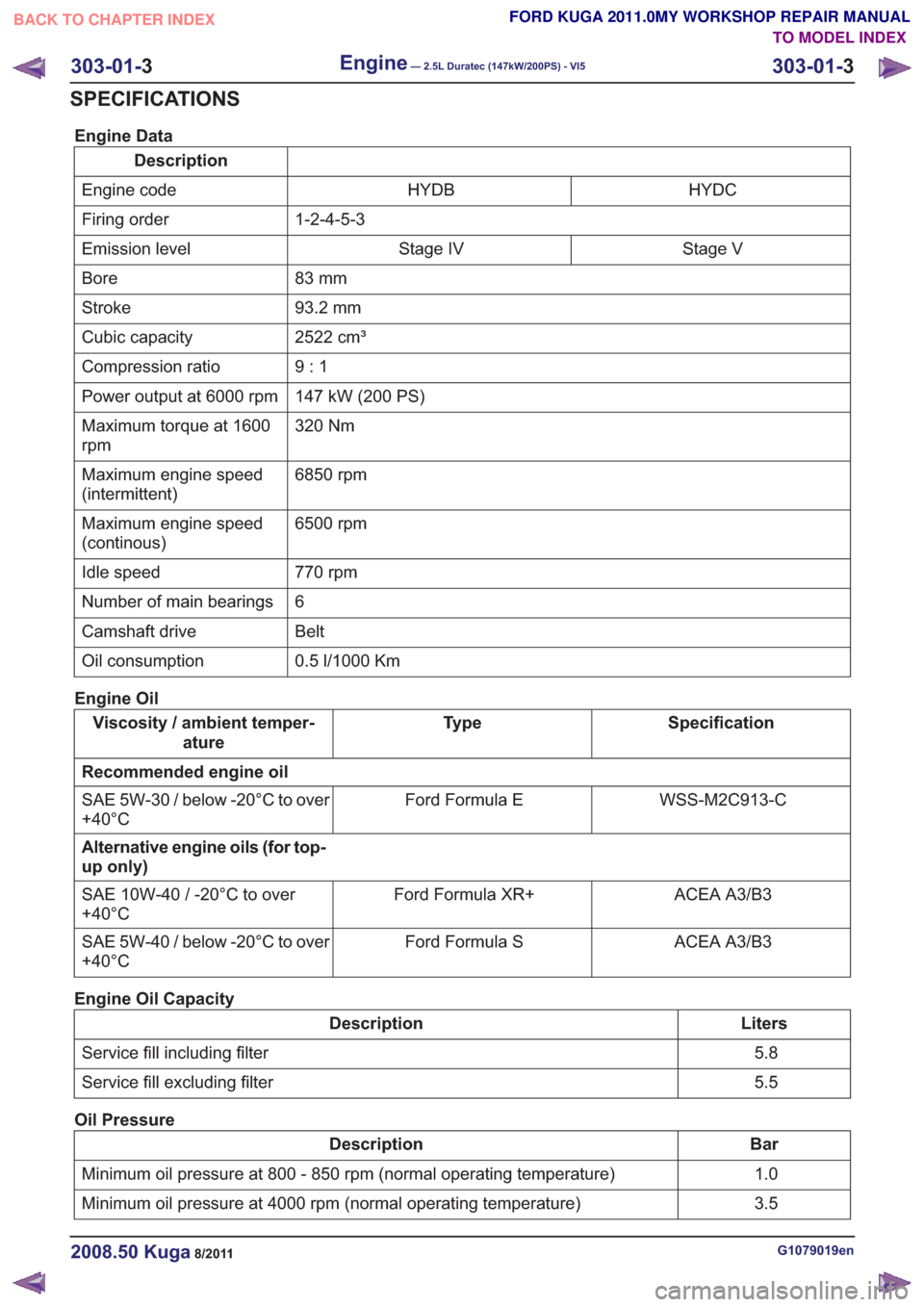
Engine Data
DescriptionHYDC
HYDB
Engine code
1-2-4-5-3
Firing order
Stage V
Stage IV
Emission level
83 mm
Bore
93.2 mm
Stroke
2522 cm³
Cubic capacity
9:1
Compression ratio
147 kW (200 PS)
Power output at 6000 rpm
320 Nm
Maximum torque at 1600
rpm
6850 rpm
Maximum engine speed
(intermittent)
6500 rpm
Maximum engine speed
(continous)
770 rpm
Idle speed
6
Number of main bearings
Belt
Camshaft drive
0.5 l/1000 Km
Oil consumption
Engine Oil
Specification
Ty p e
Viscosity / ambient temper-
ature
Recommended engine oil WSS-M2C913-C
Ford Formula E
SAE 5W-30 / below -20°C to over
+40°C
Alternative engine oils (for top-
up only)
ACEA A3/B3
Ford Formula XR+
SAE 10W-40 / -20°C to over
+40°C
ACEA A3/B3
Ford Formula S
SAE 5W-40 / below -20°C to over
+40°C
Engine Oil Capacity
Liters
Description
5.8
Service fill including filter
5.5
Service fill excluding filter
Oil Pressure
Bar
Description
1.0
Minimum oil pressure at 800 - 850 rpm (normal operating temperature)
3.5
Minimum oil pressure at 4000 rpm (normal operating temperature)
G1079019en2008.50 Kuga8/2011
303-01- 3
Engine— 2.5L Duratec (147kW/200PS) - VI5303-01-
3
SPECIFICATIONS
TO MODEL INDEX
BACK TO CHAPTER INDEX
FORD KUGA 2011.0MY WORKSHOP REPAIR MANUAL
Page 1580 of 2057
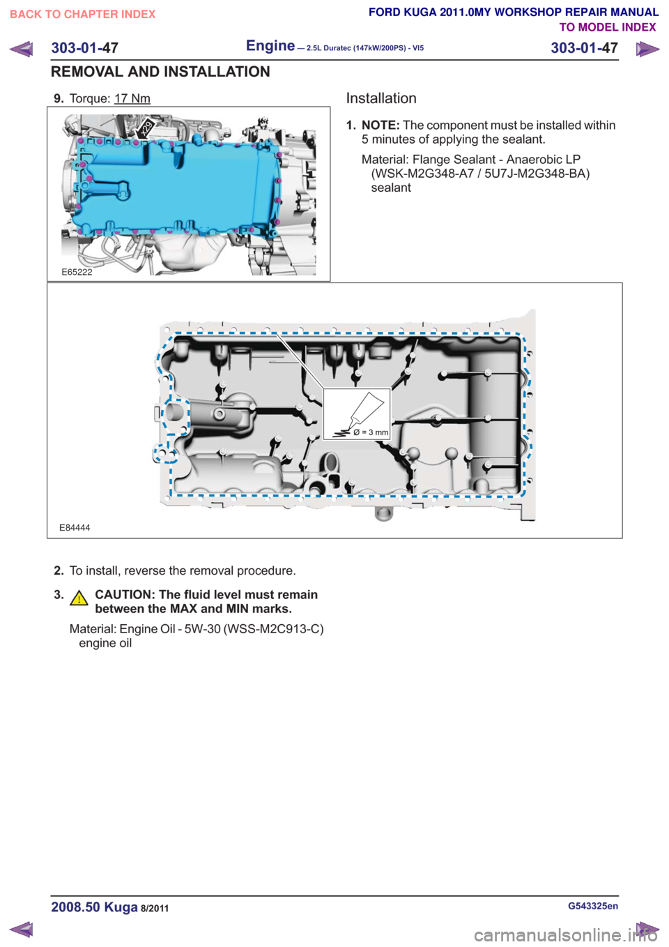
9.Torque: 17Nm
E65222
Installation
1. NOTE: The component must be installed within
5 minutes of applying the sealant.
Material: Flange Sealant - Anaerobic LP (WSK-M2G348-A7 / 5U7J-M2G348-BA)
sealant
E84444
2. To install, reverse the removal procedure.
3.
CAUTION: The fluid level must remain
between the MAX and MIN marks.
Material: Engine Oil - 5W-30 (WSS-M2C913-C) engine oil
G543325en2008.50 Kuga8/2011
303-01- 47
Engine— 2.5L Duratec (147kW/200PS) - VI5303-01-
47
REMOVAL AND INSTALLATION
TO MODEL INDEX
BACK TO CHAPTER INDEX
FORD KUGA 2011.0MY WORKSHOP REPAIR MANUAL
Page 1588 of 2057
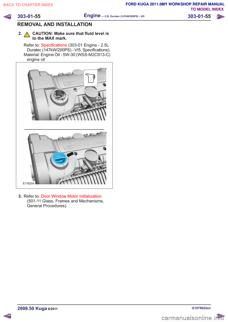
2. CAUTION: Make sure that fluid level isto the MAX mark.
Refer to: Specifications (303-01 Engine - 2.5L
Duratec (147kW/200PS) - VI5, Specifications).
Material: Engine Oil - 5W-30 (WSS-M2C913-C) engine oil
E116204
3. Refer to: Door Window Motor Initialization
(501-11 Glass, Frames and Mechanisms,
General Procedures).
G1079022en2008.50 Kuga8/2011
303-01- 55
Engine— 2.5L Duratec (147kW/200PS) - VI5303-01-
55
REMOVAL AND INSTALLATION
TO MODEL INDEX
BACK TO CHAPTER INDEX
FORD KUGA 2011.0MY WORKSHOP REPAIR MANUAL
Page 1591 of 2057
Oil Cooler(21 764 0)
General EquipmentFluid Container
Hose Clamp(s)
Materials
Specification
Name
WSS-M2C913-C
Engine Oil - 5W-30
Removal
NOTE: Removal steps in the procedure may
contain installation details.
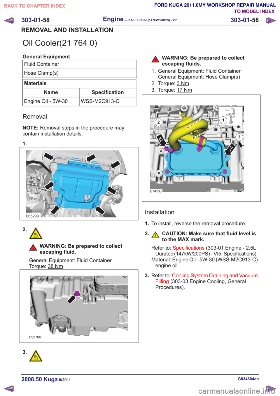
1.
E65299
2.
WARNING: Be prepared to collect
escaping fluid.
General Equipment: Fluid Container
Torque: 38
Nm
E92766
3.
WARNING: Be prepared to collect
escaping fluids.
1. General Equipment: Fluid Container General Equipment: Hose Clamp(s)
2. Torque: 3
Nm
3. Torque: 17Nm
E74103
x4
x2
2
3
1
Installation
1. To install, reverse the removal procedure.
2. CAUTION: Make sure that fluid level is to the MAX mark.
Refer to: Specifications (303-01 Engine - 2.5L
Duratec (147kW/200PS) - VI5, Specifications).
Material: Engine Oil - 5W-30 (WSS-M2C913-C) engine oil
3. Refer to: Cooling System Draining and Vacuum
Filling (303-03 Engine Cooling, General
Procedures).
G834604en2008.50 Kuga8/2011
303-01- 58
Engine— 2.5L Duratec (147kW/200PS) - VI5303-01-
58
REMOVAL AND INSTALLATION
TO MODEL INDEX
BACK TO CHAPTER INDEX
FORD KUGA 2011.0MY WORKSHOP REPAIR MANUAL
Page 1708 of 2057
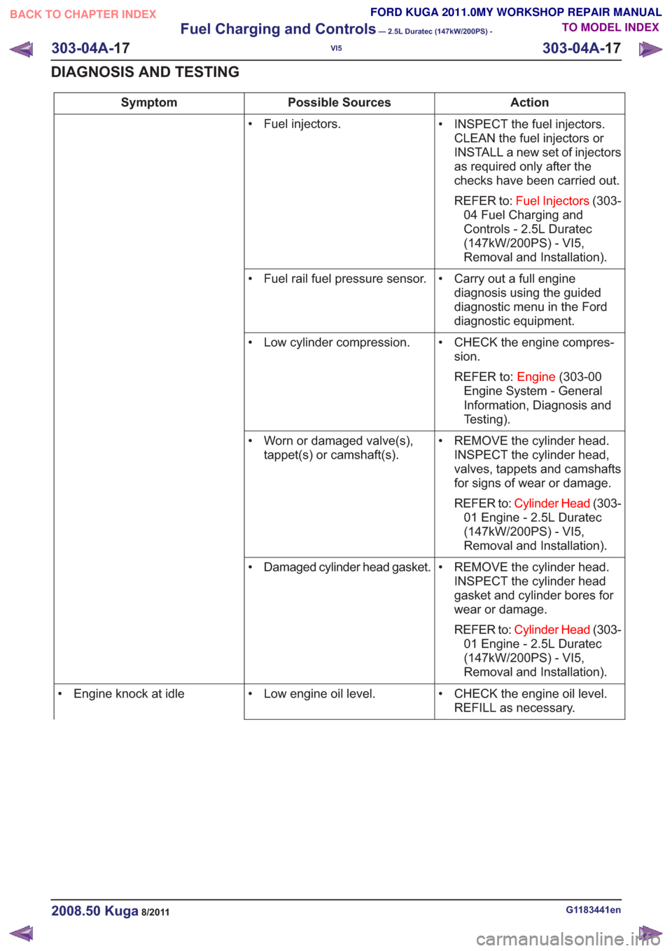
Action
Possible Sources
Symptom
• INSPECT the fuel injectors.CLEAN the fuel injectors or
INSTALL a new set of injectors
as required only after the
checks have been carried out.
REFER to: Fuel Injectors (303-
04 Fuel Charging and
Controls - 2.5L Duratec
(147kW/200PS) - VI5,
Removal and Installation).
• Fuel injectors.
• Carry out a full enginediagnosis using the guided
diagnostic menu in the Ford
diagnostic equipment.
• Fuel rail fuel pressure sensor.
• CHECK the engine compres-sion.
REFER to: Engine(303-00
Engine System - General
Information, Diagnosis and
Testing).
• Low cylinder compression.
• REMOVE the cylinder head.INSPECT the cylinder head,
valves, tappets and camshafts
for signs of wear or damage.
REFER to: Cylinder Head (303-
01 Engine - 2.5L Duratec
(147kW/200PS) - VI5,
Removal and Installation).
• Worn or damaged valve(s),
tappet(s) or camshaft(s).
• REMOVE the cylinder head.INSPECT the cylinder head
gasket and cylinder bores for
wear or damage.
REFER to: Cylinder Head (303-
01 Engine - 2.5L Duratec
(147kW/200PS) - VI5,
Removal and Installation).
• Damaged cylinder head gasket.
• CHECK the engine oil level.REFILL as necessary.
• Low engine oil level.
• Engine knock at idle
G1183441en2008.50 Kuga8/2011
303-04A- 17
Fuel Charging and Controls
— 2.5L Duratec (147kW/200PS) -
VI5
303-04A- 17
DIAGNOSIS AND TESTING
TO MODEL INDEX
BACK TO CHAPTER INDEX
FORD KUGA 2011.0MY WORKSHOP REPAIR MANUAL
Page 1775 of 2057
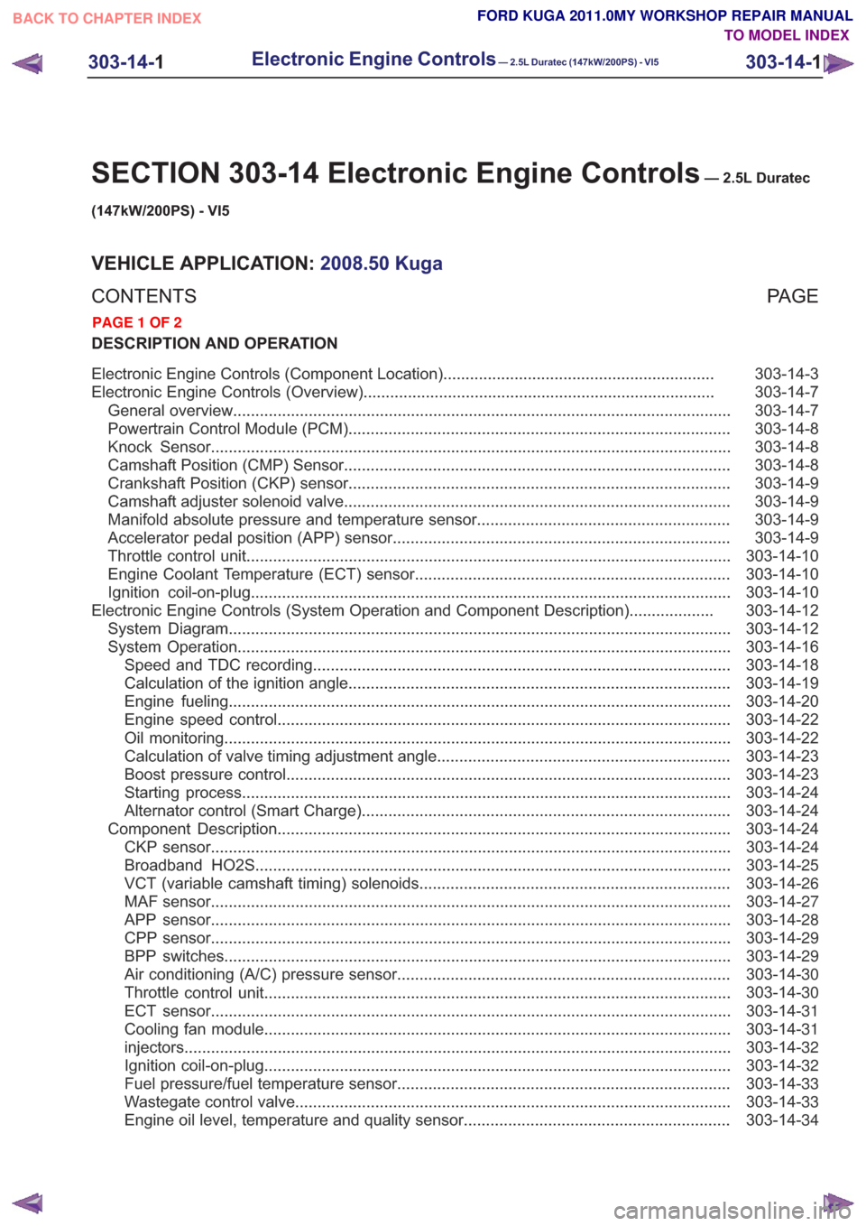
SECTION 303-14 Electronic Engine Controls— 2.5L Duratec
(147kW/200PS) - VI5
VEHICLE APPLICATION: 2008.50 Kuga
PA G E
CONTENTS
DESCRIPTION AND OPERATION
303-14-3
Electronic Engine Controls (Component Location) .............................................................
303-14-7
Electronic Engine Controls (Overview) ........................................................................\
.......
303-14-7
General overview ........................................................................\
........................................
303-14-8
Powertrain Control Module (PCM) ........................................................................\
..............
303-14-8
Knock Sensor ........................................................................\
.............................................
303-14-8
Camshaft Position (CMP) Sensor ........................................................................\
...............
303-14-9
Crankshaft Position (CKP) sensor ........................................................................\
..............
303-14-9
Camshaft adjuster solenoid valve........................................................................\
...............
303-14-9
Manifold absolute pressure and temperature sensor .........................................................
303-14-9
Accelerator pedal position (APP) sensor ........................................................................\
....
303-14-10
Throttle control unit ........................................................................\
.....................................
303-14-10
Engine Coolant Temperature (ECT) sensor.......................................................................
303-14-10
Ignition coil-on-plug ........................................................................\
....................................
303-14-12
Electronic Engine Controls (System Operation and Component Description) ...................
303-14-12
System Diagram ........................................................................\
.........................................
303-14-16
System Operation ........................................................................\
.......................................
303-14-18
Speed and TDC recording ........................................................................\
......................
303-14-19
Calculation of the ignition angle ........................................................................\
..............
303-14-20
Engine fueling ........................................................................\
.........................................
303-14-22
Engine speed control ........................................................................\
..............................
303-14-22
Oil monitoring ........................................................................\
..........................................
303-14-23
Calculation of valve timing adjustment angle..................................................................
303-14-23
Boost pressure control ........................................................................\
............................
303-14-24
Starting process ........................................................................\
......................................
303-14-24
Alternator control (Smart Charge) ........................................................................\
...........
303-14-24
Component Description ........................................................................\
..............................
303-14-24
CKP sensor ........................................................................\
.............................................
303-14-25
Broadband HO2S ........................................................................\
...................................
303-14-26
VCT (variable camshaft timing) solenoids ......................................................................
303-14-27
MAF sensor ........................................................................\
.............................................
303-14-28
APP sensor ........................................................................\
.............................................
303-14-29
CPP sensor ........................................................................\
.............................................
303-14-29
BPP switches ........................................................................\
..........................................
303-14-30
Air conditioning (A/C) pressure sensor ........................................................................\
...
303-14-30
Throttle
control unit ........................................................................\
.................................
303-14-31
ECT sensor ........................................................................\
.............................................
303-14-31
Cooling fan module ........................................................................\
.................................
303-14-32
injectors........................................................................\
...................................................
303-14-32
Ignition coil-on-plug ........................................................................\
.................................
303-14-33
Fuel pressure/fuel temperature sensor ........................................................................\
...
303-14-33
Wastegate control valve ........................................................................\
..........................
303-14-34
Engine oil level, temperature and quality sensor ............................................................
303-14-1
Electronic Engine Controls— 2.5L Duratec (147kW/200PS) - VI5303-14-
1
.
TO MODEL INDEX
BACK TO CHAPTER INDEX
PAGE 1 OF 2
FORD KUGA 2011.0MY WORKSHOP REPAIR MANUAL
Page 1788 of 2057
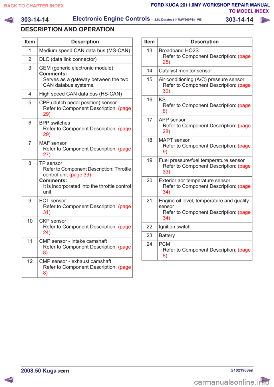
Description
Item
Medium speed CAN data bus (MS-CAN)
1
DLC (data link connector)
2
GEM (generic electronic module)
Comments:Serves as a gateway between the two
CAN databus systems.
3
High speed CAN data bus (HS-CAN)
4
CPP (clutch pedal position) sensorRefertoComponentDescription:(page
29)
5
BPP switchesRefertoComponentDescription:(page
29)
6
MAF sensorRefertoComponentDescription:(page
27)
7
TP sensorRefer to Component Description: Throttle
controlunit(page33)
Comments: It is incorporated into the throttle control
unit
8
ECT sensorRefertoComponentDescription:(page
31)
9
CKP sensorRefertoComponentDescription:(page
24)
10
CMP sensor - intake camshaftRefertoComponentDescription:(page
8)
11
CMP sensor - exhaust camshaftRefertoComponentDescription:(page
8)
12Description
Item
Broadband HO2SRefertoComponentDescription:(page
25)
13
Catalyst monitor sensor
14
Air conditioning (A/C) pressure sensorRefertoComponentDescription:(page
30)
15
KSRefertoComponentDescription:(page
8)
16
APP sensorRefertoComponentDescription:(page
28)
17
MAPT sensorRefertoComponentDescription:(page
9)
18
Fuel pressure/fuel temperature sensorRefertoComponentDescription:(page
33)
19
Exterior aor temperature sensorRefertoComponentDescription:(page
34)
20
Engine oil level, temperature and quality
sensorRefertoComponentDescription:(page
34)
21
Ignition switch
22
Battery
23
PCMRefertoComponentDescription:(page
8)
24
G1021908en2008.50 Kuga8/2011
303-14-
14
Electronic Engine Controls— 2.5L Duratec (147kW/200PS) - VI5303-14-
14
DESCRIPTION AND OPERATION
TO MODEL INDEX
BACK TO CHAPTER INDEX
FORD KUGA 2011.0MY WORKSHOP REPAIR MANUAL
Page 1791 of 2057
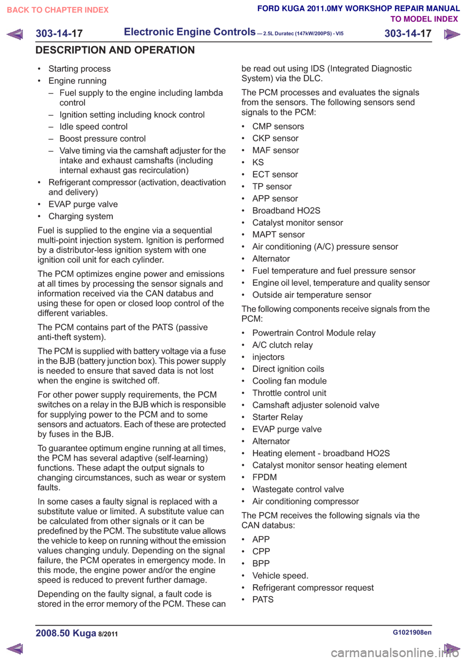
• Starting process
• Engine running– Fuel supply to the engine including lambdacontrol
– Ignition setting including knock control
– Idle speed control
– Boost pressure control
– Valve timing via the camshaft adjuster for the intake and exhaust camshafts (including
internal exhaust gas recirculation)
• Refrigerant compressor (activation, deactivation and delivery)
• EVAP purge valve
• Charging system
Fuel is supplied to the engine via a sequential
multi-point injection system. Ignition is performed
by a distributor-less ignition system with one
ignition coil unit for each cylinder.
The PCM optimizes engine power and emissions
at all times by processing the sensor signals and
information received via the CAN databus and
using these for open or closed loop control of the
different variables.
The PCM contains part of the PATS (passive
anti-theft system).
The PCM is supplied with battery voltage via a fuse
in the BJB (battery junction box). This power supply
is needed to ensure that saved data is not lost
when the engine is switched off.
For other power supply requirements, the PCM
switches on a relay in the BJB which is responsible
for supplying power to the PCM and to some
sensors and actuators. Each of these are protected
by fuses in the BJB.
To guarantee optimum engine running at all times,
the PCM has several adaptive (self-learning)
functions. These adapt the output signals to
changing circumstances, such as wear or system
faults.
In some cases a faulty signal is replaced with a
substitute value or limited. A substitute value can
be calculated from other signals or it can be
predefined by the PCM. The substitute value allows
the vehicle to keep on running without the emission
values changing unduly. Depending on the signal
failure, the PCM operates in emergency mode. In
this mode, the engine power and/or the engine
speed is reduced to prevent further damage.
Depending on the faulty signal, a fault code is
stored in the error memory of the PCM. These can be read out using IDS (Integrated Diagnostic
System) via the DLC.
The PCM processes and evaluates the signals
from the sensors. The following sensors send
signals to the PCM:
• CMP sensors
• CKP sensor
• MAF sensor
•KS
• ECT sensor
• TP sensor
• APP sensor
• Broadband HO2S
• Catalyst monitor sensor
• MAPT sensor
• Air conditioning (A/C) pressure sensor
• Alternator
• Fuel temperature and fuel pressure sensor
• Engine oil level, temperature and quality sensor
• Outside air temperature sensor
The following components receive signals from the
PCM:
• Powertrain Control Module relay
• A/C clutch relay
• injectors
• Direct ignition coils
• Cooling fan module
• Throttle control unit
• Camshaft adjuster solenoid valve
• Starter Relay
• EVAP purge valve
• Alternator
• Heating element - broadband HO2S
• Catalyst monitor sensor heating element
• FPDM
• Wastegate control valve
• Air conditioning compressor
The PCM receives the following signals via the
CAN databus:
• APP
•CPP
• BPP
• Vehicle speed.
• Refrigerant compressor request
• PAT S
G1021908en2008.50 Kuga8/2011
303-14-
17
Electronic Engine Controls— 2.5L Duratec (147kW/200PS) - VI5303-14-
17
DESCRIPTION AND OPERATION
TO MODEL INDEX
BACK TO CHAPTER INDEX
FORD KUGA 2011.0MY WORKSHOP REPAIR MANUAL