2011 FORD KUGA low oil pressure
[x] Cancel search: low oil pressurePage 190 of 2057

Instrument Cluster
Refer to
Wiring Diagrams Section 413-01, for
schematic and connector information. General Equipment
The Ford approved diagnostic tool
Inspection and Verification
1. Verify the customer concern.
2. Visually inspect for obvious signs of mechanical
or electrical damage.
Visual Inspection Chart Electrical
Mechanical
– Fuse(s)
– Wiring harness
– Electricalconnector(s)
– Instrument cluster
– Light emitting diode(s) (LED)(s)
– Engine oil filter
– Engine oil level
–
Engine coolant level
– Oil pressure switch
– Engine coolant level
– Coolant thermostat
– Engine coolant temperature (ECT)
sensor
– Fuel gauge
– Collapsed or damaged fuel tank
– Recirculation hose
– Fuel tank filler pipe/hose
– Indicated fuel level
– Fuel lines
– Fuel tank filler cap
– Fuel filter (external to the fuel tank)
– Fuel tank
– Door adjustment
3. If an obvious cause for an observed or reported concern is found, correct the cause (if possible)
before proceeding to the next step.
4. NOTE: If none of the following warning indicators are operating correctly this may
indicate a concern with the central junction
box (CJB). If only one or two of the following
warning indicators are not operating
correctly this may indicate an instrument
cluster concern. Verify the following warning indicators are
working correctly:
• Charging.
• Turn signals.
• Headlamps.
5. If the cause is not visually evident, verify the symptom and refer to the diagnostic tab within
the Ford approved diagnostic tool.
Configuration of the Instrument Cluster
The instrument cluster is a programmable module,
which must be configured by selecting the
Programmable Module Installation Routine on the
Ford approved diagnostic tool.
NOTE: When the new instrument cluster has been
configured with the odometer value, its
configuration cannot be decreased or matched. A
new configuration will result in an increase in the
displayed odometer value by a minimum of two
units.
NOTE: The odometer value must be recorded from
the original instrument cluster before removal.
If the odometer value cannot be obtained from
the original instrument cluster (display failure)
the customer should supply the approximate
value.
The following features will need to be configured
when a new instrument cluster is installed:
• Anti-lock Brake System (ABS)
• All wheel drive
• Keyless vehicle entry
• Electronic power assisted steering
• Trip computer
• Voice control
• Parking aid
• Belt minder
• Safety belt not fastened
• Right hand drive
• Overspeed warning
• Reverse warning
• Turbocharger boost pressure
• Speed control
• Auxiliary heater
• Suspension control
• Washer fluid sensor G1054964en
2008.50 Kuga 8/2011 413-01-7
Instrument Cluster
413-01-7
DIAGNOSIS AND TESTINGTO MODEL INDEX
BACK TO CHAPTER INDEX
FORD KUGA 2011.0MY WORKSHOP REPAIR MANUAL
Page 1525 of 2057
Action
Possible Sources
Symptom
• CHECK the engine compon-ents for wear or damage. Make
sure that all components are
within specification. INSTALL
new components as necessary.
Engine - 2.5L Duratec-ST (VI5)
-
REFER to: Specifications (303-
01 Engine - 2.5L Duratec
(147kW/200PS) - VI5,
Specifications).
Engine - 2.0L Duratorq-TDCi
(DW) Diesel -
• Engine components
- Pistons.
- Piston rings.
- Connecting rod big end,main bearing or thrust
bearing journals.
- Connecting rods bent or damaged.
• Noisy running or engine noise
Engine - Oil Leaks
NOTE:
Before installing new gaskets or oil seals,
make sure that the fault is clearly established.
If the oil leak cannot be identified clearly by a visual
inspection, carry out an ultraviolet (UV) test:
Ultraviolet (UV) Testing
1. Clean the engine and transmission with a suitable cleaning fluid.
2. Pour the UV-test fluid in accordance with the quantity specified by the manufacturer through
the oil filler neck into the engine and install the
oil filler cap.
WARNING: Vehicles with manual transaxle,
shift the transaxle into Neutral. Failure to
follow this instruction may result in
personal injury.
3. Start the engine and let it run for about five minutes.
4. Switch off the engine.
NOTE: If no leak can be found, road test the
vehicle under various loads and check the engine
for leaks again.
5. Check the engine for oil leaks using a suitable UV lamp.
6. Rectify any leaks found and check the engine for oil leaks.
Measure the compression pressure
NOTE: The powertrain control module (PCM)
receives an error message when the fuel pump
relay is removed or electrical components are disconnected. This error message must be deleted
from the fault memory using the Ford diagnostic
equipment after completing the compression test.
NOTE:
Valve clearance must be set correctly
before performing a compression test. Make sure
the engine is at the normal operating temperature.
NOTE: The varying design of compression
checking devices and fluctuating starter motor
speeds normally only allows for a comparison to
be made of the compression pressures in all
cylinders.
G1055128en2008.50 Kuga8/2011
303-00- 9
Engine System - General Information
303-00- 9
DIAGNOSIS AND TESTING
TO MODEL INDEX
BACK TO CHAPTER INDEX
FORD KUGA 2011.0MY WORKSHOP REPAIR MANUAL
Page 1527 of 2057
9. Install the ignition coil-on-plug.REFER to: Ignition Coil-On-Plug (303-07 Engine
Ignition - 2.5L Duratec (147kW/200PS) - VI5,
Removal and Installation).
TIE44609
10. Install the fuel pump relay and close the CJB.
TIE44608
11. Install the CJB cover.
Measure the compression pressure
(Engine - 2.0L Duratorq-TDCi (DW)
Diesel)
WARNINGS:
Do not smoke or carry lighted tobacco or
open flame of any type when working on or near any fuel related components.
Highly flammable vapors are always
present and can ignite. Failure to follow
these instructions may result in personal
injury.
Do not carry out any repairs to the fuel
injection system without checking that the
fuel pressure has dropped to zero and that
the fuel temperature has either reached
ambient temperature or is below 30°C,
whichever is the greater. Failure to follow
these instructions may result in personal
injury.
1. Using datalogger in the Ford diagnostic
equipment , check that the fuel pressure has
dropped to zero and that the fuel temperature
has either reached ambient temperature or is
below 30°C, whichever is the greater.
2. Raise and support the vehicle.
REFER to: Lifting(100-02 Jacking and Lifting,
Description and Operation).
VFE0035742
3. Remove the engine undershield.
VFE0035752
4. Remove the radiator undershield.
G1055128en2008.50 Kuga8/2011
303-00- 11
Engine System - General Information
303-00- 11
DIAGNOSIS AND TESTING
TO MODEL INDEX
BACK TO CHAPTER INDEX
FORD KUGA 2011.0MY WORKSHOP REPAIR MANUAL
Page 1530 of 2057
Put the engine cover into installation position
and clip it in place by pressing at the places
shown.• Make sure that the engine upper cover is fully engaged in the area of the fuel filter, if
necessary apply more pressure in the areas
shown.
25. Install the cowl panel grille.
REFER to: Cowl Panel Grille (501-02 Front End
Body Panels, Removal and Installation).
26. Raise and support the vehicle.
REFER to: Lifting(100-02 Jacking and Lifting,
Description and Operation).
TIE44583
27. Install the glow plug relay.
VFE0035752
28. Install the radiator undershield.
VFE0035742
29. Install the engine undershield.
30. Lower the vehicle.
31. Reset the PCM fault memory.
Measure the oil pressure (21 113 0)
The oil pressure depends on various factors
(engine speed, oil temperature, oil viscosity,
amount of oil filter contamination etc.).
Measure the oil pressure (Engine - 2.5L
Duratec-ST (VI5))
1. Raise and support the vehicle.
REFER to: Lifting(100-02 Jacking and Lifting,
Description and Operation).
E65955
2. Remove the engine undershield.
E68443
3. Disconnect the oil pressure switch electrical connector.
G1055128en2008.50 Kuga8/2011
303-00- 14
Engine System - General Information
303-00- 14
DIAGNOSIS AND TESTING
TO MODEL INDEX
BACK TO CHAPTER INDEX
FORD KUGA 2011.0MY WORKSHOP REPAIR MANUAL
Page 1531 of 2057
E68435
4. Remove the oil pressure switch.
E68436
5. Attach the oil pressure gauge with the oilpressure gauge connector to the oil pressure
switch bore, and position it to allow reading from
above.
6. Lower the vehicle.
E68436
7. NOTE: Measure the oil pressure at an oil temperature of 100°C.
NOTE: Measure the oil pressure at idle speed and
at 4000 rpm.
NOTE: Minimum oil pressure at idle speed: 1.0
bar.
NOTE: Minimum oil pressure at 4000 rpm: 3.5 bar.
NOTE: Maximum oil pressure: 4.8 bar. Measure the oil pressure.
8. Raise and support the vehicle.
REFER to: Lifting(100-02 Jacking and Lifting,
Description and Operation).
E68436
9. Detach the oil pressure gauge and connector from the oil pressure switch bore.
10. Coat the oil pressure switch with adhesive.
E68435
11. Install the oil pressure switch.
E68443
12. Connect the oil pressure switch electrical
connector to the oil pressure switch.
G1055128en2008.50 Kuga8/2011
303-00- 15
Engine System - General Information
303-00- 15
DIAGNOSIS AND TESTING
TO MODEL INDEX
BACK TO CHAPTER INDEX
FORD KUGA 2011.0MY WORKSHOP REPAIR MANUAL
Page 1532 of 2057
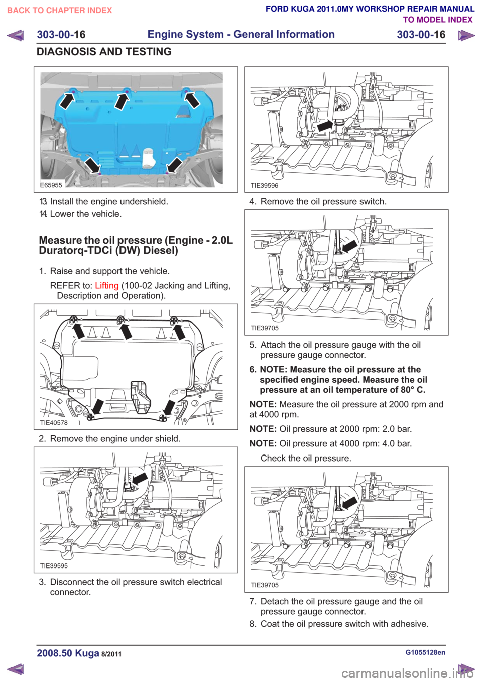
E65955
13. Install the engine undershield.
14. Lower the vehicle.
Measure the oil pressure (Engine - 2.0L
Duratorq-TDCi (DW) Diesel)
1. Raise and support the vehicle.REFER to: Lifting(100-02 Jacking and Lifting,
Description and Operation).
TIE40578
2. Remove the engine under shield.
TIE39595
3. Disconnect the oil pressure switch electrical connector.
TIE39596
4. Remove the oil pressure switch.
TIE39705
5. Attach the oil pressure gauge with the oilpressure gauge connector.
6. NOTE: Measure the oil pressure at the specified engine speed. Measure the oil
pressure at an oil temperature of 80° C.
NOTE: Measure the oil pressure at 2000 rpm and
at 4000 rpm.
NOTE: Oil pressure at 2000 rpm: 2.0 bar.
NOTE: Oil pressure at 4000 rpm: 4.0 bar.
Check the oil pressure.
TIE39705
7. Detach the oil pressure gauge and the oil pressure gauge connector.
8. Coat the oil pressure switch with adhesive.
G1055128en2008.50 Kuga8/2011
303-00-16
Engine System - General Information
303-00- 16
DIAGNOSIS AND TESTING
TO MODEL INDEX
BACK TO CHAPTER INDEX
FORD KUGA 2011.0MY WORKSHOP REPAIR MANUAL
Page 1533 of 2057
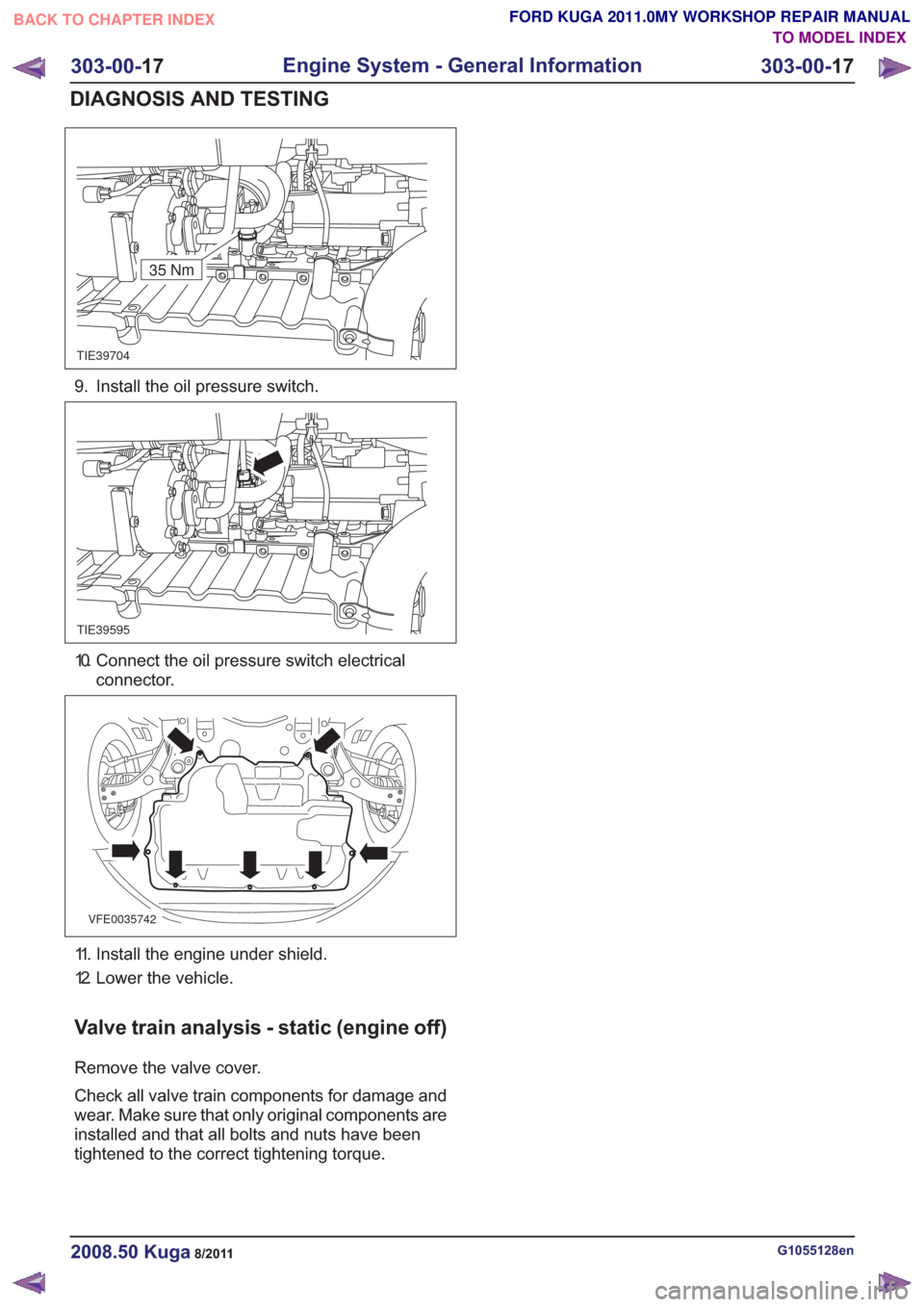
TIE39704
35 Nm
9. Install the oil pressure switch.
TIE39595
10. Connect the oil pressure switch electricalconnector.
VFE0035742
11. Install the engine under shield.
12. Lower the vehicle.
Valve train analysis - static (engine off)
Remove the valve cover.
Check all valve train components for damage and
wear. Make sure that only original components are
installed and that all bolts and nuts have been
tightened to the correct tightening torque.
G1055128en2008.50 Kuga8/2011
303-00- 17
Engine System - General Information
303-00- 17
DIAGNOSIS AND TESTING
TO MODEL INDEX
BACK TO CHAPTER INDEX
FORD KUGA 2011.0MY WORKSHOP REPAIR MANUAL
Page 1536 of 2057
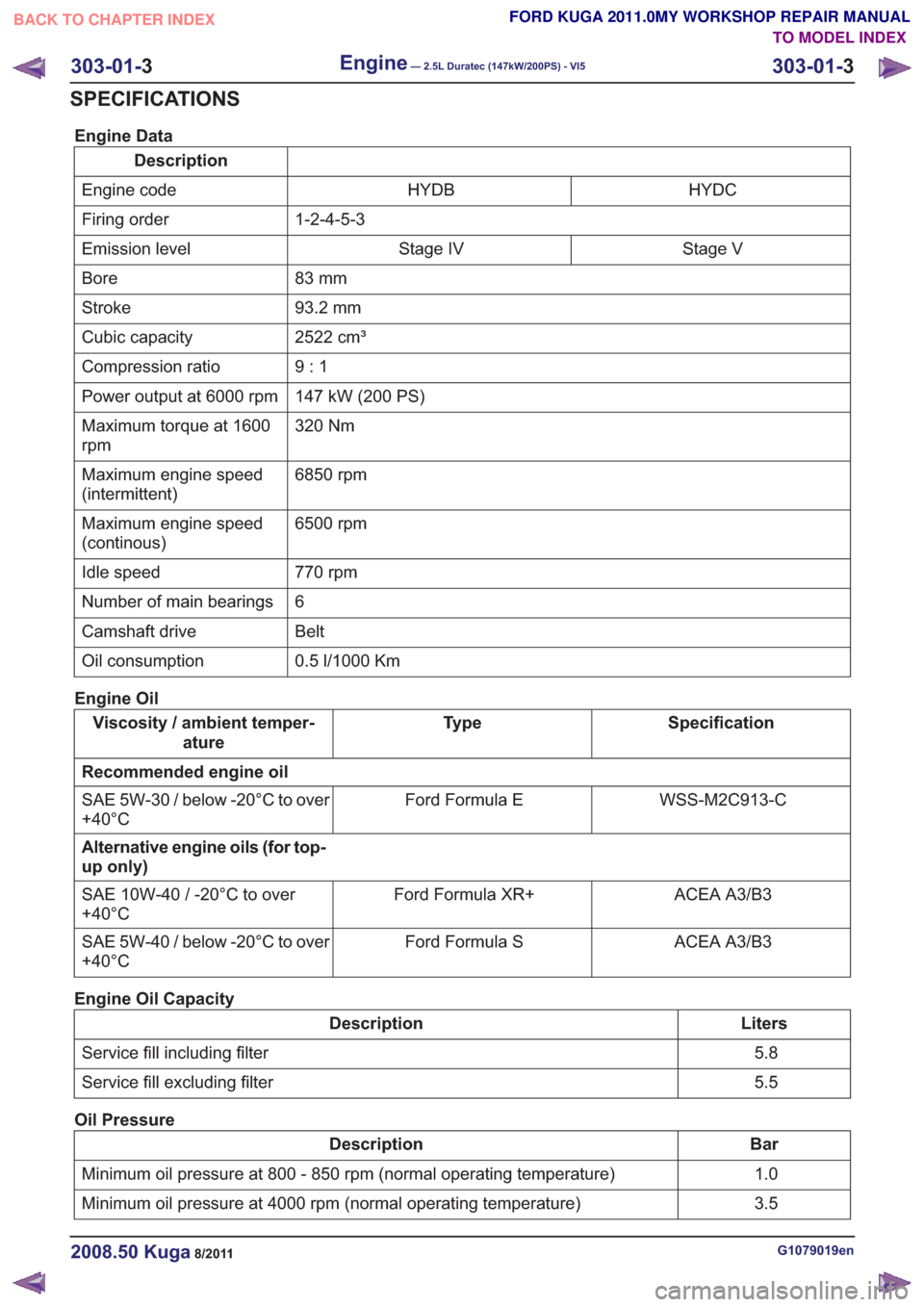
Engine Data
DescriptionHYDC
HYDB
Engine code
1-2-4-5-3
Firing order
Stage V
Stage IV
Emission level
83 mm
Bore
93.2 mm
Stroke
2522 cm³
Cubic capacity
9:1
Compression ratio
147 kW (200 PS)
Power output at 6000 rpm
320 Nm
Maximum torque at 1600
rpm
6850 rpm
Maximum engine speed
(intermittent)
6500 rpm
Maximum engine speed
(continous)
770 rpm
Idle speed
6
Number of main bearings
Belt
Camshaft drive
0.5 l/1000 Km
Oil consumption
Engine Oil
Specification
Ty p e
Viscosity / ambient temper-
ature
Recommended engine oil WSS-M2C913-C
Ford Formula E
SAE 5W-30 / below -20°C to over
+40°C
Alternative engine oils (for top-
up only)
ACEA A3/B3
Ford Formula XR+
SAE 10W-40 / -20°C to over
+40°C
ACEA A3/B3
Ford Formula S
SAE 5W-40 / below -20°C to over
+40°C
Engine Oil Capacity
Liters
Description
5.8
Service fill including filter
5.5
Service fill excluding filter
Oil Pressure
Bar
Description
1.0
Minimum oil pressure at 800 - 850 rpm (normal operating temperature)
3.5
Minimum oil pressure at 4000 rpm (normal operating temperature)
G1079019en2008.50 Kuga8/2011
303-01- 3
Engine— 2.5L Duratec (147kW/200PS) - VI5303-01-
3
SPECIFICATIONS
TO MODEL INDEX
BACK TO CHAPTER INDEX
FORD KUGA 2011.0MY WORKSHOP REPAIR MANUAL