2011 FORD KUGA low oil pressure
[x] Cancel search: low oil pressurePage 1797 of 2057
Calculation of valve timing adjustment
angle
The 2.5L Duratec (VI5) engine has two camshaft
adjustment units which work independently of each
other.
One camshaft adjustment solenoid is installed for
each intake camshaft and exhaust camshaft.
This allows the PCM to continuously adjust the
intake and exhaust-side camshaft adjustments
independently of one another. The timing is
adjusted by the PCM using curves; adjustment is
primarily done as a function of engine load and
engine speed.
In this way the engine performance is increased
and internal exhaust gas recirculation is realized.
The advantages of camshaft adjustment are as
follows:
• Higher torque and improved torquecharacteristics
• Reduced fuel consumption
• Improved emissions performance
The camshaft adjustment solenoids are actuated
by the PWM by means of a PCM signal.
Continuous adjustment of the camshafts by the
PCM is achieved by means of the camshaft
adjustment solenoids, the camshaft adjustment
units and two CMP sensors. A defined quantity of
engine is oil is supplied to or drained from the
adjustment units via the camshaft adjustment
solenoids. The existing EOP (engine oil pressure)
is taken into account in the process. In this way
the valve timings are adjusted according to the
operating condition of the engine. The camshaft
adjusters work according to the vane-cell principle.
On starting the engine, both camshafts are
mechanically locked in their starting positions. The
intake camshaft is in the maximum late position
and the exhaust camshaft in the maximum early
position.
Control is divided into four main areas:
• Low engine speed and low load
• Partial load
• Low engine speed and high load
• High engine speed and high load
At low engine speed and low load, the exhaust
valves open early and the intake valves open late.
The result is reduced fuel consumption and more
uniform idling. In the partial load range, the exhaust valves and
the intake valves open late. The late opening of
the exhaust valves results in a good utilization of
the expanding gases in the cylinder. Closing the
exhaust valves after Top Dead Center allows
internal exhaust gas recirculation through aspiration
of exhaust gases into the combustion chamber.
Moreover, the intake valves close after Bottom
Dead Centre, allowing the fresh air/fuel mixture
and exhaust gases to flow back into the intake
tract. The result is reduced fuel consumption and
low emissions.
At low engine speed and high engine load, the
exhaust valves open late and the intake valves
open early. Due to the resulting valve opening
overlap at Top Dead Centre, the pulsating gas
column within the combustion chamber is utilized
to achieve better charging of the combustion
chamber. The result is increased torque at lower
RPM.
At high engine speeds and high engine load, the
exhaust valves open early and the intake valves
close late. Because a rapid gas exchange must be
achieved at high engine speeds, the early opening
of the exhaust valves achieves better expulsion of
the exhaust gas and the late closing of the intake
valves improves cylinder charge efficiency.
Optimum power output is achieved.
Many other camshaft positions are possible in
addition to these settings.
In order to avoid a malfunction in the camshaft
adjustment units at excessively low ambient or
engine-oil temperatures, they are activated by the
PCM with a time delay via the camshaft adjustment
solenoids. The PCM receives the information
required for this from the ECT sensor and the
outside air temperature sensor.
When idling and during deceleration, the camshaft
adjustment solenoids are activated repeatedly by
the PCM in order to remove any dirt which may be
on the bore holes and ring grooves.
Boost pressure control
Optimum regulation is achieved by means of an
electronically-controlled solenoid valve, the boost
control solenoid valve.
Refer to:
Turbocharger (303-04 Fuel Charging and
Controls - Turbocharger - 2.5L Duratec
(147kW/200PS) - VI5, Description and
Operation).
G1021908en2008.50 Kuga8/2011
303-14- 23
Electronic Engine Controls— 2.5L Duratec (147kW/200PS) - VI5303-14-
23
DESCRIPTION AND OPERATION
TO MODEL INDEX
BACK TO CHAPTER INDEX
FORD KUGA 2011.0MY WORKSHOP REPAIR MANUAL
Page 1801 of 2057
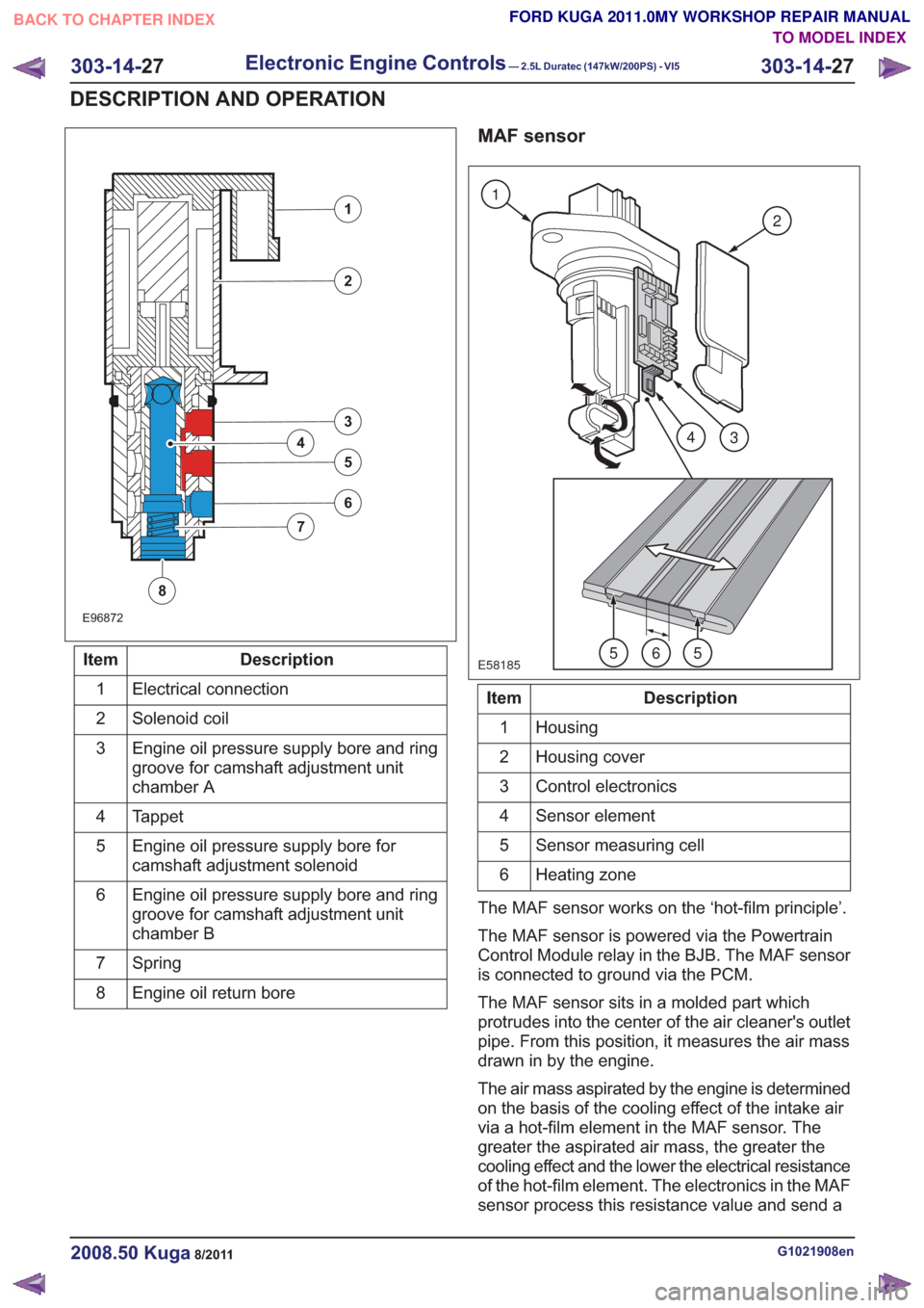
E96872
1
2
3
5
4
6
7
8
Description
Item
Electrical connection
1
Solenoid coil
2
Engine oil pressure supply bore and ring
groove for camshaft adjustment unit
chamber A
3
Tappet
4
Engine oil pressure supply bore for
camshaft adjustment solenoid
5
Engine oil pressure supply bore and ring
groove for camshaft adjustment unit
chamber B
6
Spring
7
Engine oil return bore
8
MAF sensor
E58185
1
2
43
565
Description
Item
Housing
1
Housing cover
2
Control electronics
3
Sensor element
4
Sensor measuring cell
5
Heating zone
6
The MAF sensor works on the ‘hot-film principle’.
The MAF sensor is powered via the Powertrain
Control Module relay in the BJB. The MAF sensor
is connected to ground via the PCM.
The MAF sensor sits in a molded part which
protrudes into the center of the air cleaner's outlet
pipe. From this position, it measures the air mass
drawn in by the engine.
The air mass aspirated by the engine is determined
on the basis of the cooling effect of the intake air
via a hot-film element in the MAF sensor. The
greater the aspirated air mass, the greater the
cooling effect and the lower the electrical resistance
of the hot-film element. The electronics in the MAF
sensor process this resistance value and send a
G1021908en2008.50 Kuga8/2011
303-14- 27
Electronic Engine Controls— 2.5L Duratec (147kW/200PS) - VI5303-14-
27
DESCRIPTION AND OPERATION
TO MODEL INDEX
BACK TO CHAPTER INDEX
FORD KUGA 2011.0MY WORKSHOP REPAIR MANUAL
Page 1807 of 2057
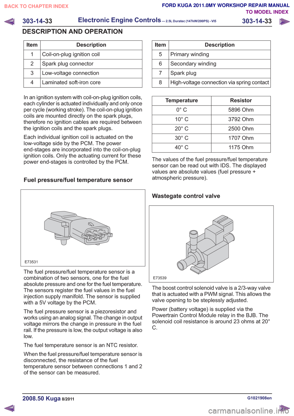
Description
Item
Coil-on-plug ignition coil
1
Spark plug connector
2
Low-voltage connection
3
Laminated soft-iron core
4Description
Item
Primary winding
5
Secondary winding
6
Spark plug
7
High-voltage connection via spring contact
8
In an ignition system with coil-on-plug ignition coils,
each cylinder is actuated individually and only once
per cycle (working stroke). The coil-on-plug ignition
coils are mounted directly on the spark plugs,
therefore no ignition cables are required between
the ignition coils and the spark plugs.
Each individual ignition coil is actuated on the
low-voltage side by the PCM. The power
end-stages are incorporated into the coil-on-plug
ignition coils. Only the actuating current for these
power end-stages is controlled by the PCM.
Fuel pressure/fuel temperature sensor
E73531
The fuel pressure/fuel temperature sensor is a
combination of two sensors, one for the fuel
absolute pressure and one for the fuel temperature.
The sensors register the fuel values in the fuel
injection supply manifold. The sensor is supplied
with a 5V voltage by the PCM.
The fuel pressure sensor is a piezoresistor and
works using an analog signal. The change in output
voltage mirrors the change in pressure in the fuel
rail. If the pressure is low, the output voltage is also
low.
The fuel temperature sensor is an NTC resistor.
When the fuel pressure/fuel temperature sensor is
disconnected, the resistance of the fuel
temperature sensor between connections 1 and 2
of the sensor can be measured.
Resistor
Temperature
5896 Ohm
0° C
3792 Ohm
10° C
2500 Ohm
20° C
1707 Ohm
30° C
1175 Ohm
40° C
The values of the fuel pressure/fuel temperature
sensor can be read out with IDS. The displayed
values are absolute values (fuel pressure +
atmospheric pressure).
Wastegate control valve
E73539
The boost control solenoid valve is a 2/3-way valve
that is actuated with a PWM signal. This allows the
valve opening to be steplessly adjusted.
Power (battery voltage) is supplied via the
Powertrain Control Module relay in the BJB. The
solenoid coil resistance is around 23 ohms at 20°
C.
G1021908en2008.50 Kuga8/2011
303-14- 33
Electronic Engine Controls— 2.5L Duratec (147kW/200PS) - VI5303-14-
33
DESCRIPTION AND OPERATION
TO MODEL INDEX
BACK TO CHAPTER INDEX
FORD KUGA 2011.0MY WORKSHOP REPAIR MANUAL
Page 1823 of 2057
307-01-29
Automatic transmission, selector lever in position "D". ...................................................
307-01-29
Sport mode, selector lever in position "S" .......................................................................
307-01-29
Changing gear in select-shift mode........................................................................\
........
307-01-30
Selector lever from 'N' to 'R' position ........................................................................\
......
307-01-30
Self-test and Diagnosis ........................................................................\
...........................
307-01-30
Temperature controlled torque converter lockup ............................................................
307-01-30
Slip locking ........................................................................\
..............................................
307-01-30
Hill climbing ........................................................................\
.............................................
307-01-31
Downhill driving ........................................................................\
.......................................
307-01-31
Hill-hold function ........................................................................\
.....................................
307-01-31
Altitude correction ........................................................................\
...................................
307-01-31
Selector lever lock ........................................................................\
..................................
307-01-31
Shifting from P into another transmission range .............................................................
307-01-31
Shifting from N into another transmission range .............................................................
307-01-31
Power flow through the transmission ........................................................................\
......
307-01-31
Clutches and brakes ........................................................................\
...............................
307-01-33
Position P (park) ........................................................................\
.....................................
307-01-34
Position N (neutral) ........................................................................\
.................................
307-01-35
Position D, 1st gear........................................................................\
................................
307-01-36
Position D, 2nd gear ........................................................................\
...............................
307-01-37
Position D, 3rd gear ........................................................................\
................................
307-01-38
Position D, 4th gear ........................................................................\
................................
307-01-39
Position D, 5th gear ........................................................................\
................................
307-01-40
Position R (reverse) ........................................................................\
................................
307-01-41
Service instructions ........................................................................\
.................................
307-01-41
Towing procedure ........................................................................\
...................................
307-01-42
Reset adaptation data ........................................................................\
.............................
307-01-42
Limp home mode ........................................................................\
....................................
307-01-42
Component Description ........................................................................\
..............................
Tasks of the electronic components ........................................................................\
........
307-01-44
Input signals ........................................................................\
............................................
307-01-45
Output signals ........................................................................\
.........................................
Control valve assembly ........................................................................\
...........................
Shift solenoids S1 - S5 ........................................................................\
...........................
PWM-
solenoid valve – TCC (SLU) ........................................................................\
........
PWM solenoid valve – shift pressure (SLS) ...................................................................
PWM solenoid valve for main line pressure (SLT) ..........................................................
307-01-52
Installation position ........................................................................\
.................................
Operation ........................................................................\
................................................
Selector lever with integrated select-shift switch module ...............................................
Oil pump ........................................................................\
..................................................
Torque converter with TCC ........................................................................\
.....................
The TSS sensor ........................................................................\
......................................
The OSS sensor ........................................................................\
.....................................
The TFT sensor ........................................................................\
......................................
The TR sensor ........................................................................\
........................................
GENERAL PROCEDURES
T ransmission Fluid Level Check ........................................................................\
.................
307-01-63
T ransmission Fluid Drain and Refill ........................................................................\
............
REMOVAL AND INSTALLATION 307-01-67
Halfshaft Seal LH ........................................................................\
........................................
307-01-68
Halfshaft Seal RH........................................................................\
.......................................
307-01-69
Main Control Valve Body ........................................................................\
............................
307-01-2
Automatic Transmission/Transaxle
— Vehicles With:
5-Speed Automatic Transaxle - AW55 AWD
307-01- 2
.
TO MODEL INDEX
BACK TO CHAPTER INDEX
307-01-42
307-01-49
307-01-52 307-01-47
307-01-45
307-01-50
307-01-51
307-01-53
307-01-55
307-01-54
307-01-56
307-01-57
307-01-58
307-01-61 307-01-60
PAGE 2 OF 3 FORD KUGA 2011.0MY WORKSHOP REPAIR MANUAL
Page 1971 of 2057
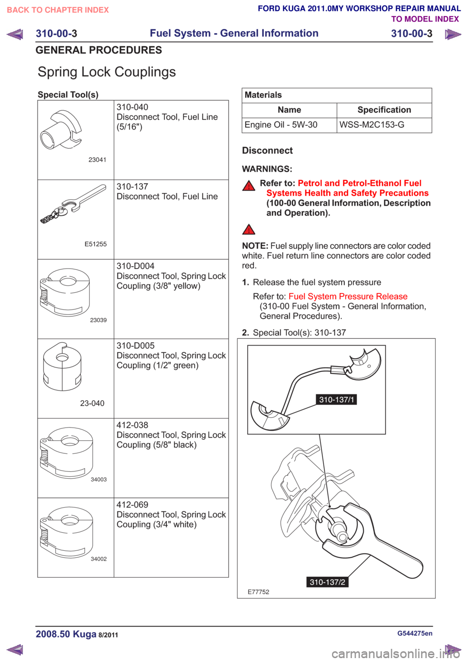
Spring Lock Couplings
Special Tool(s)310-040
Disconnect Tool, Fuel Line
(5/16")
23041
310-137
Disconnect Tool, Fuel Line
E51255
310-D004
Disconnect Tool, Spring Lock
Coupling (3/8" yellow)
23039
310-D005
Disconnect Tool, Spring Lock
Coupling (1/2" green)
23-040
412-038
Disconnect Tool, Spring Lock
Coupling (5/8" black)
34003
412-069
Disconnect Tool, Spring Lock
Coupling (3/4" white)
34002
Materials
Specification
Name
WSS-M2C153-G
Engine Oil - 5W-30
Disconnect
WARNINGS:
Refer to: Petrol and Petrol-Ethanol Fuel
Systems Health and Safety Precautions
(100-00 General Information, Description
and Operation).
NOTE: Fuel supply line connectors are color coded
white. Fuel return line connectors are color coded
red.
1. Release the fuel system pressure
Refer to: Fuel System Pressure Release
(310-00 Fuel System - General Information,
General Procedures).
2. Special Tool(s): 310-137
E77752
G544275en2008.50 Kuga8/2011
310-00- 3
Fuel System - General Information
310-00- 3
GENERAL PROCEDURES
TO MODEL INDEX
BACK TO CHAPTER INDEX
FORD KUGA 2011.0MY WORKSHOP REPAIR MANUAL
Page 2018 of 2057
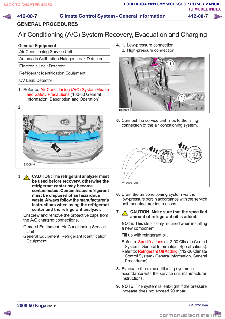
Air Conditioning (A/C) System Recovery, Evacuation and Charging
General EquipmentAir Conditioning Service Unit
Automatic Calibration Halogen Leak Detector
Electronic Leak Detector
Refrigerant Identification Equipment
UV Leak Detector
1. Refer to: Air Conditioning (A/C) System Health
and Safety Precautions (100-00 General
Information, Description and Operation).
2.
E100846
x4
3. CAUTION: The refrigerant analyzer must be used before recovery, otherwise the
refrigerant center may become
contaminated. Contaminated refrigerant
must be disposed of as hazardous
waste. Always follow the manufacturer's
instructions when using the refrigerant
center and the refrigerant analyzer.
Unscrew and remove the protective caps from
the A/C charging connections.
General Equipment: Air Conditioning Service Unit
General Equipment: Refrigerant Identification Equipment 4.
Low-pressure connection
1.
2. High-pressure connection
2
E51608
1
5. Connect the service unit lines to the filling
connection of the air conditioning system.
VFE0031288
6.Drain the air conditioning system via the
low-pressure port in accordance with the service
unit manufacturer instructions.
7. CAUTION: Make sure that the specified amount of refrigerant oil is added.
NOTE:This step is only required when installing
a new component.
Fill up with refrigerant oil.
Refer to: Specifications (412-00 Climate Control
System - General Information, Specifications).
Refer to: Refrigerant Oil Adding (412-00 Climate
Control System - General Information, General
Procedures).
8. Evacuate the air conditioning system in
accordance with the service unit manufacturer
instructions.
9. NOTE: The system is leak-tight if the pressure
increase does not exceed 20 mbar.
G1022208en2008.50 Kuga8/2011
412-00- 7
Climate Control System - General Information
412-00- 7
GENERAL PROCEDURES
TO MODEL INDEX
BACK TO CHAPTER INDEX
FORD KUGA 2011.0MY WORKSHOP REPAIR MANUAL
Page 2019 of 2057
Perform the leak test, by closing the hand valves
on the gauge set, switching off the service unit
vacuum pump and observing the low pressure
gauge.
10. N O T E : This step is only necessary if the
pressure increase exceeds 20 mbar.
Locate and rectify any leaks in the A/C
refrigerant circuit using a leak tester.
General Equipment: UV Leak Detector
General Equipment: Electronic Leak Detector
General Equipment: Automatic Calibration Halogen Leak Detector
11 . Add refrigerant oil to the air conditioning system.
Refer to: Specifications (412-00 Climate Control
System - General Information, Specifications).
Refer to: Refrigerant Oil Adding (412-00 Climate
Control System - General Information, General
Procedures).
12. Fill the air conditioning system with liquid
through the high-pressure connection.
Refer to: Specifications (412-00 Climate Control
System - General Information, Specifications).
13. Open the shut-off valve on the high-pressure
side.
1.
2. Switch the service unit to "Fill" mode and fill
the system with the specified quantity of
liquid refrigerant (R134a).
14. Fill the air conditioning system with gas through
the low-pressure connection.
Refer to: Specifications (412-00 Climate Control
System - General Information, Specifications).
15. Open the shut-off valve on the low-pressure
side.
1.
2. Switch the service unit to "Fill" mode and fill
the system with the specified quantity of
gaseous refrigerant.
3. Add the remaining amount of refrigerant with the air conditioning switched on. To do so
run the engine at about 1200-1500 rev/min.
Set the air conditioning system to full cooling
power and fresh air mode. Set the blower
motor to the highest setting. Fill with the
remainder of the specified fill capacity.
16. Disconnect the service unit. 17.
Close the shut-off valve.
1.
2. Switch off the service unit.
3. Disconnect the service unit lines from the
filling connections of the air conditioning
system.
4. Screw the protective caps onto the charging connections.
18. Install all components in reverse order.
G1022208en2008.50 Kuga8/2011
412-00- 8
Climate Control System - General Information
412-00- 8
GENERAL PROCEDURES
TO MODEL INDEX
BACK TO CHAPTER INDEX
FORD KUGA 2011.0MY WORKSHOP REPAIR MANUAL