Page 1546 of 2057

Description
Item
Exhaust camshaft
1
intake camshaft
2
Valve cover
3
CMP Sensor - intake camshaft
4Description
Item
Intake camshaft reference mark
5
Exhaust camshaft reference mark
6
CMP Sensor - exhaust camshaft
7
CAUTION: Before removal, mark the
camshafts as the intake and exhaust
camshafts can be mixed up.
A reference mark for the CMP sensor is machined
into each camshaft. When the camshafts are set
precisely to the timing marks, the machined mark
on the exhaust camshaft is located roughly at the
5 o'clock position and the machined mark on the
intake camshaft is located at 8 o'clock.
When changing the toothed belts it is not necessary
to dismantle the camshaft adjustment units. A
special tool prevents the VCT control units from
turning during the adjustment process by locking
the two VCT control units to one another.
A further special tool is needed to fix the camshafts
in the adjustment position. The special tool
engages in corresponding recesses for the
reference marks on the CMP sensors. Each camshaft is fixed in place using four bearing
caps and the bearing cap VVT. The bearing caps
must not be changed around and must always be
fitted in their original positions.
The VCT control units for the intake and exhaust
camshafts are moved into the locked base position
when the engine is stopped through the
engagement of a spring-loaded locking pin. The
movement to the locked base position is assisted
by the tensile force of the timing belt for the intake
VCT control unit. With the exhaust VCT control
unit, a spring inside the control unit additionally
assists in reaching the locked base position. The
intake VCT control unit is in the "retarded timing"
position and the exhaust VCT control unit is in the
"advanced timing" position when in the locked base
position. The lock is hydraulically released when
the engine is started depending on the oil pressure.
The mechanical valve tappets are maintenance
free.
G1092773en2008.50 Kuga8/2011
303-01-
13
Engine— 2.5L Duratec (147kW/200PS) - VI5303-01-
13
DESCRIPTION AND OPERATION
TO MODEL INDEX
BACK TO CHAPTER INDEX
FORD KUGA 2011.0MY WORKSHOP REPAIR MANUAL
Page 1547 of 2057

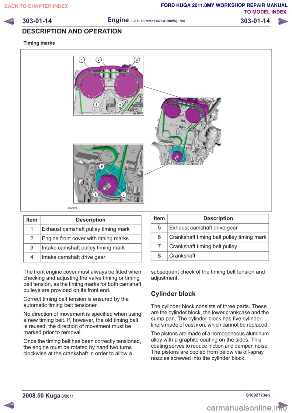
Timing marks
132
45
6
78
E62440
Description
Item
Exhaust camshaft pulley timing mark
1
Engine front cover with timing marks
2
Intake camshaft pulley timing mark
3
Intake camshaft drive gear
4Description
Item
Exhaust camshaft drive gear
5
Crankshaft timing belt pulley timing mark
6
Crankshaft timing belt pulley
7
Crankshaft
8
The front engine cover must always be fitted when
checking and adjusting the valve timing or timing
belt tension, as the timing marks for both camshaft
pulleys are provided on its front end.
Correct timing belt tension is ensured by the
automatic timing belt tensioner.
No direction of movement is specified when using
a new timing belt. If, however, the old timing belt
is reused, the direction of movement must be
marked prior to removal.
Once the timing belt has been correctly tensioned,
the engine must be rotated by hand two turns
clockwise at the crankshaft in order to allow a subsequent check of the timing belt tension and
adjustment.
Cylinder block
The cylinder block consists of three parts. These
are the cylinder block, the lower crankcase and the
sump pan. The cylinder block has five cylinder
liners made of cast iron, which cannot be replaced.
The pistons are made of a homogeneous aluminum
alloy with a graphite coating on the sides. This
coating serves to reduce friction and dampen noise.
The pistons are cooled from below via oil-spray
nozzles screwed into the cylinder block.
G1092773en2008.50 Kuga8/2011
303-01-
14
Engine— 2.5L Duratec (147kW/200PS) - VI5303-01-
14
DESCRIPTION AND OPERATION
TO MODEL INDEX
BACK TO CHAPTER INDEX
FORD KUGA 2011.0MY WORKSHOP REPAIR MANUAL
Page 1549 of 2057

Engine – System Operation and Component Description
System Operation
The variable camshaft timing occurs
electro-hydraulically and individually for both
camshafts.
The camshaft adjusters work according to the vane
cell principle and have an adjustment range of 52°
crank angle on the intake side and 47° crank angle
on the exhaust side. On starting the engine and
during idling, both camshafts are mechanically
locked in their starting positions. The exhaust
camshaft is in the early position and the intake
camshaft is in the late position. The camshaftadjuster on the exhaust side has a torsion spring
which compensates the camshaft drive torque.
This ensures that the assembly can return to the
starting position under all operating conditions and
when the engine is turned off.
Internal exhaust gas recirculation can be realized
through continuous adjustment of the timings. This
results in better fuel consumption and more
favorable combustion temperatures which produce
less pollutants. This means that pollutant level IV
can be adhered to with a 3-way catalytic converter.
The variable timings also make it possible to
optimize performance with wide open throttle.
G1032416en2008.50 Kuga8/2011
303-01-
16
Engine— 2.5L Duratec (147kW/200PS) - VI5303-01-
16
DESCRIPTION AND OPERATION
TO MODEL INDEX
BACK TO CHAPTER INDEX
FORD KUGA 2011.0MY WORKSHOP REPAIR MANUAL
Page 1550 of 2057
Variable camshaft timing
Timing retard
E62711
Description
Item
Camshaft pulley
1
Locking pin
2
Valve rotor
3
Rotor vane
4
Plunger
5Description
Item
Return spring
6
Camshaft adjuster solenoid
7
Duct connected to chamber (a)
A
Duct connected to chamber (b)
B
Oil feed duct
C
Oil return duct
Drive
G1032416en2008.50 Kuga8/2011
303-01- 17
Engine— 2.5L Duratec (147kW/200PS) - VI5303-01-
17
DESCRIPTION AND OPERATION
TO MODEL INDEX
BACK TO CHAPTER INDEX
FORD KUGA 2011.0MY WORKSHOP REPAIR MANUAL
Page 1551 of 2057

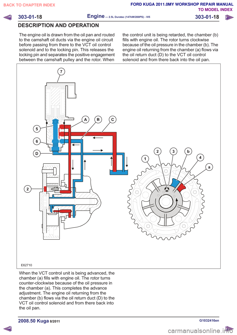
The engine oil is drawn from the oil pan and routed
to the camshaft oil ducts via the engine oil circuit
before passing from there to the VCT oil control
solenoid and to the locking pin. This releases the
locking pin and separates the positive engagement
between the camshaft pulley and the rotor. Whenthe control unit is being retarded, the chamber (b)
fills with engine oil. The rotor turns clockwise
because of the oil pressure in the chamber (b). The
engine oil returning from the chamber (a) flows via
the oil return duct (D) to the VCT oil control
solenoid and from there back into the oil pan.
E62710
When the VCT control unit is being advanced, the
chamber (a) fills with engine oil. The rotor turns
counter-clockwise because of the oil pressure in
the chamber (a). This completes the advance
adjustment. The engine oil returning from the
chamber (b) flows via the oil return duct (D) to the
VCT oil control solenoid and from there back into
the oil pan.
G1032416en2008.50 Kuga8/2011
303-01-
18
Engine— 2.5L Duratec (147kW/200PS) - VI5303-01-
18
DESCRIPTION AND OPERATION
TO MODEL INDEX
BACK TO CHAPTER INDEX
FORD KUGA 2011.0MY WORKSHOP REPAIR MANUAL
Page 1558 of 2057
Timing Belt(21 304 0)
Special Tool(s) / General Equipment303-1054
Locking Tool, Timing Belt
Tensioner
3031054
303-1179
Holding Wrench, Crankshaft
E62035
Trolley Jack
Two Leg Puller
Removal
1.Refer to: Air Conditioning (A/C) Compressor
Belt (303-05 Accessory Drive - 2.5L Duratec
(147kW/200PS) - VI5, Removal and
Installation).
2.
E68741
3. General Equipment: Trolley Jack
E66944
4.
E68472
2
1
5.
E68742
G543492en2008.50 Kuga8/2011
303-01- 25
Engine— 2.5L Duratec (147kW/200PS) - VI5303-01-
25
REMOVAL AND INSTALLATION
TO MODEL INDEX
BACK TO CHAPTER INDEX
FORD KUGA 2011.0MY WORKSHOP REPAIR MANUAL
Page 1569 of 2057
Camshaft Seal(21 288 0)
Special Tool(s)303-1054
Locking Tool, Timing Belt
Tensioner
3031054
303-1178
Timing Tool Camshaft
E62051
303-1179
Holding Wrench, Crankshaft
E62035
303-1182
Timing Tool, Crankshaft
E62027
303-318
Aligner/Installer, Crankshaft
Front Seal
21148
Removal
1.Remove the following items:
1. Refer to: Ignition Coil-On-Plug (303-07
Engine Ignition - 2.5L Duratec
(147kW/200PS) - VI5, Removal and
Installation).
2. Refer to: Starter Motor (303-06 Starting
System - 2.5L Duratec (147kW/200PS) -
VI5, Removal and Installation).
2.
E67902
3.
E68679
x5
G1166799en2008.50 Kuga8/2011
303-01- 36
Engine— 2.5L Duratec (147kW/200PS) - VI5303-01-
36
REMOVAL AND INSTALLATION
TO MODEL INDEX
BACK TO CHAPTER INDEX
FORD KUGA 2011.0MY WORKSHOP REPAIR MANUAL
Page 1589 of 2057
Crankshaft Rear Seal(21 468 4)
Special Tool(s)303-1181
Installer, Crankshaft Rear
Seal
E62048
303-254
Locking Tool, Flywheel
21135
303-293
Remover, Crankshaft Seal
21143
Removal
Vehicles with manual transmission
1.
Vehicles with automatic transmission
2.Refer to: Transmission (307-01 Automatic
Transmission/Transaxle - Vehicles With:
5-Speed Automatic Transaxle - AW55 AWD,
Removal).
All vehicles
3. Special Tool(s): 303-254
E64889
4.Special Tool(s): 303-293
E64890
303-293
G1268481en2008.50 Kuga8/2011
303-01- 56
Engine— 2.5L Duratec (147kW/200PS) - VI5303-01-
56
REMOVAL AND INSTALLATION
TO MODEL INDEX
BACK TO CHAPTER INDEX
FORD KUGA 2011.0MY WORKSHOP REPAIR MANUAL