Page 1477 of 2057
3.
E141078
4. NOTE:Make sure the fluid in the reservoir does
not fall below the MIN mark, as air could enter
the system.
Slowly turn the steering wheel from lock to lock
five times.
E131522
123
5.
E141079
12
6.
E141077
G1176952en2008.50 Kuga8/2011
211-02- 20
Power Steering
211-02- 20
REMOVAL AND INSTALLATION
TO MODEL INDEX
BACK TO CHAPTER INDEX
FORD KUGA 2011.0MY WORKSHOP REPAIR MANUAL
Page 1481 of 2057
Installation
1.To install, reverse the removal procedure.
2.
E141077
3.
E141078
4. NOTE: Make sure the fluid in the reservoir does
not fall below the MIN mark, as air could enter
the system.
Slowly turn the steering wheel from lock to lock
five times.
E131522
123
5.
E141079
12
6.
E141077
G1185535en2008.50 Kuga8/2011
211-02- 24
Power Steering
211-02- 24
REMOVAL AND INSTALLATION
TO MODEL INDEX
BACK TO CHAPTER INDEX
FORD KUGA 2011.0MY WORKSHOP REPAIR MANUAL
Page 1482 of 2057

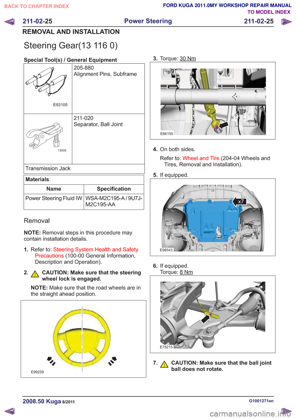
Steering Gear(13 116 0)
Special Tool(s) / General Equipment205-880
Alignment Pins, Subframe
E93105
211-020
Separator, Ball Joint
13006
Transmission Jack
Materials
Specification
Name
WSA-M2C195-A / 9U7J-
M2C195-AA
Power Steering Fluid IW
Removal
NOTE:
Removal steps in this procedure may
contain installation details.
1. Refer to: Steering System Health and Safety
Precautions (100-00 General Information,
Description and Operation).
2. CAUTION: Make sure that the steering wheel lock is engaged.
NOTE: Make sure that the road wheels are in
the straight ahead position.
E99259
3. Torque: 30Nm
E66155
4.On both sides.
Refer to: Wheel and Tire (204-04 Wheels and
Tires, Removal and Installation).
5. If equipped.
E98543
x7
6.If equipped.
Torque: 8
Nm
E75215
7. CAUTION: Make sure that the ball joint
ball does not rotate.
G1001271en2008.50 Kuga8/2011
211-02- 25
Power Steering
211-02- 25
REMOVAL AND INSTALLATION
TO MODEL INDEX
BACK TO CHAPTER INDEX
FORD KUGA 2011.0MY WORKSHOP REPAIR MANUAL
Page 1489 of 2057
E131502
7. NOTE:Make sure the fluid in the reservoir does
not fall below the MIN mark, as air could enter
the system. Slowly turn the steering wheel from lock to lock
five times.
E131522
123
8.
Material: Power Steering Fluid IW
(WSA-M2C195-A / 9U7J-M2C195-AA)
hydraulic fluid
G1001271en2008.50 Kuga8/2011
211-02- 32
Power Steering
211-02- 32
REMOVAL AND INSTALLATION
TO MODEL INDEX
BACK TO CHAPTER INDEX
FORD KUGA 2011.0MY WORKSHOP REPAIR MANUAL
Page 1491 of 2057
Vehicles with 2.5L engine
11 .
E141077
12.
E141078
13. N O T E :Make sure the fluid in the reservoir does
not fall below the MIN mark, as air could enter
the system.
Slowly turn the steering wheel from lock to lock
five times.
E131522
123
14.
E141079
12
15.
E141077
G1001271en2008.50 Kuga8/2011
211-02- 34
Power Steering
211-02- 34
REMOVAL AND INSTALLATION
TO MODEL INDEX
BACK TO CHAPTER INDEX
FORD KUGA 2011.0MY WORKSHOP REPAIR MANUAL
Page 1496 of 2057
Installation
1.To install, reverse the removal procedure.
2.
E141077
3.
E141078
4. NOTE: Make sure the fluid in the reservoir does
not fall below the MIN mark, as air could enter
the system.
Slowly turn the steering wheel from lock to lock
five times.
E131522
123
5.
E141079
12
6.
E141077
G1185536en2008.50 Kuga8/2011
211-02- 39
Power Steering
211-02- 39
REMOVAL AND INSTALLATION
TO MODEL INDEX
BACK TO CHAPTER INDEX
FORD KUGA 2011.0MY WORKSHOP REPAIR MANUAL
Page 1503 of 2057
Steering Column – Overview
General overview
E98628
1
2
3
4
5
6
7
8
9
Description
Item
Driver airbag
Refer to: Air Bag and Safety Belt
Pretensioner Supplemental Restraint
System (SRS) (501-20 Supplemental
Restraint System, Description and
Operation).
1
Steering wheel
2
Switch unit, steering column
Refer to: Steering Column Switches
(211-05 Steering Column Switches,
Description and Operation).
3Description
Item
Steering column lower shroud
4
Steering column upper shroud
5
Steering Column
6
Steering lock
7
Extension, steering shaft
8
Steering gear to bulkhead seal
9
G1030751en2008.50 Kuga8/2011
211-04- 2
Steering Column
211-04- 2
DESCRIPTION AND OPERATION
TO MODEL INDEX
BACK TO CHAPTER INDEX
FORD KUGA 2011.0MY WORKSHOP REPAIR MANUAL
Page 1504 of 2057

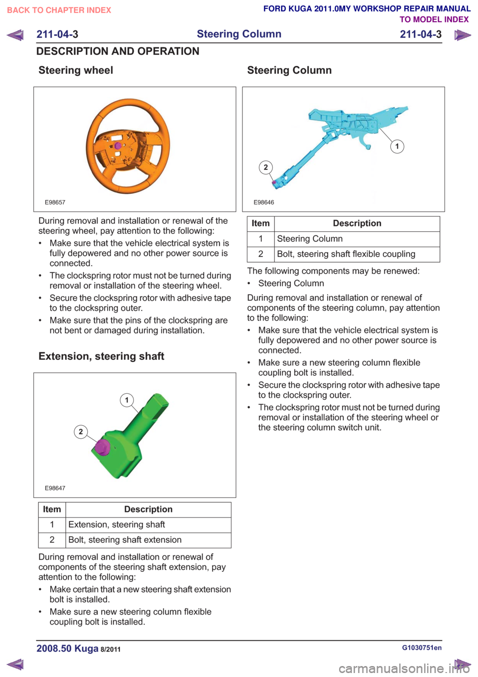
Steering wheel
E98657
During removal and installation or renewal of the
steering wheel, pay attention to the following:
• Make sure that the vehicle electrical system isfully depowered and no other power source is
connected.
• The clockspring rotor must not be turned during removal or installation of the steering wheel.
• Secure the clockspring rotor with adhesive tape to the clockspring outer.
• Make sure that the pins of the clockspring are not bent or damaged during installation.
Extension, steering shaft
E98647
1
2
Description
Item
Extension, steering shaft
1
Bolt, steering shaft extension
2
During removal and installation or renewal of
components of the steering shaft extension, pay
attention to the following:
• Make certain that a new steering shaft extension bolt is installed.
• Make sure a new steering column flexible coupling bolt is installed.
Steering Column
E98646
1
2
Description
Item
Steering Column
1
Bolt, steering shaft flexible coupling
2
The following components may be renewed:
• Steering Column
During removal and installation or renewal of
components of the steering column, pay attention
to the following:
• Make sure that the vehicle electrical system is fully depowered and no other power source is
connected.
• Make sure a new steering column flexible coupling bolt is installed.
• Secure the clockspring rotor with adhesive tape to the clockspring outer.
• The clockspring rotor must not be turned during removal or installation of the steering wheel or
the steering column switch unit.
G1030751en2008.50 Kuga8/2011
211-04- 3
Steering Column
211-04- 3
DESCRIPTION AND OPERATION
TO MODEL INDEX
BACK TO CHAPTER INDEX
FORD KUGA 2011.0MY WORKSHOP REPAIR MANUAL