2011 FORD KUGA lock
[x] Cancel search: lockPage 1720 of 2057
Turbocharger – Overview
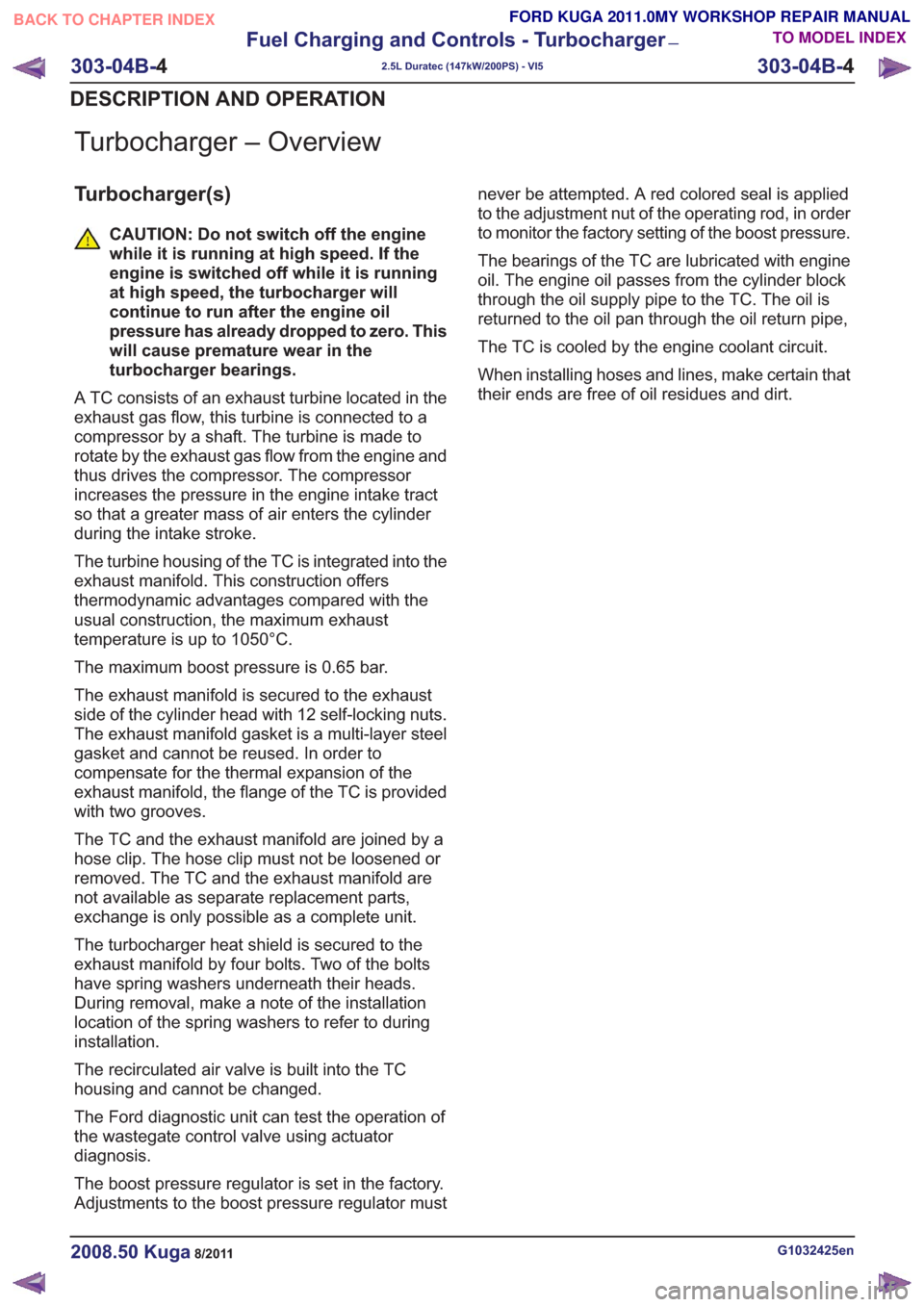
Turbocharger(s)
CAUTION: Do not switch off the engine
while it is running at high speed. If the
engine is switched off while it is running
at high speed, the turbocharger will
continue to run after the engine oil
pressure has already dropped to zero. This
will cause premature wear in the
turbocharger bearings.
A TC consists of an exhaust turbine located in the
exhaust gas flow, this turbine is connected to a
compressor by a shaft. The turbine is made to
rotate by the exhaust gas flow from the engine and
thus drives the compressor. The compressor
increases the pressure in the engine intake tract
so that a greater mass of air enters the cylinder
during the intake stroke.
The turbine housing of the TC is integrated into the
exhaust manifold. This construction offers
thermodynamic advantages compared with the
usual construction, the maximum exhaust
temperature is up to 1050°C.
The maximum boost pressure is 0.65 bar.
The exhaust manifold is secured to the exhaust
side of the cylinder head with 12 self-locking nuts.
The exhaust manifold gasket is a multi-layer steel
gasket and cannot be reused. In order to
compensate for the thermal expansion of the
exhaust manifold, the flange of the TC is provided
with two grooves.
The TC and the exhaust manifold are joined by a
hose clip. The hose clip must not be loosened or
removed. The TC and the exhaust manifold are
not available as separate replacement parts,
exchange is only possible as a complete unit.
The turbocharger heat shield is secured to the
exhaust manifold by four bolts. Two of the bolts
have spring washers underneath their heads.
During removal, make a note of the installation
location of the spring washers to refer to during
installation.
The recirculated air valve is built into the TC
housing and cannot be changed.
The Ford diagnostic unit can test the operation of
the wastegate control valve using actuator
diagnosis.
The boost pressure regulator is set in the factory.
Adjustments to the boost pressure regulator must never be attempted. A red colored seal is applied
to the adjustment nut of the operating rod, in order
to monitor the factory setting of the boost pressure.
The bearings of the TC are lubricated with engine
oil. The engine oil passes from the cylinder block
through the oil supply pipe to the TC. The oil is
returned to the oil pan through the oil return pipe,
The TC is cooled by the engine coolant circuit.
When installing hoses and lines, make certain that
their ends are free of oil residues and dirt.
G1032425en2008.50 Kuga8/2011
303-04B-
4
Fuel Charging and Controls - Turbocharger
—
2.5L Duratec (147kW/200PS) - VI5
303-04B- 4
DESCRIPTION AND OPERATION
TO MODEL INDEX
BACK TO CHAPTER INDEX
FORD KUGA 2011.0MY WORKSHOP REPAIR MANUAL
Page 1726 of 2057
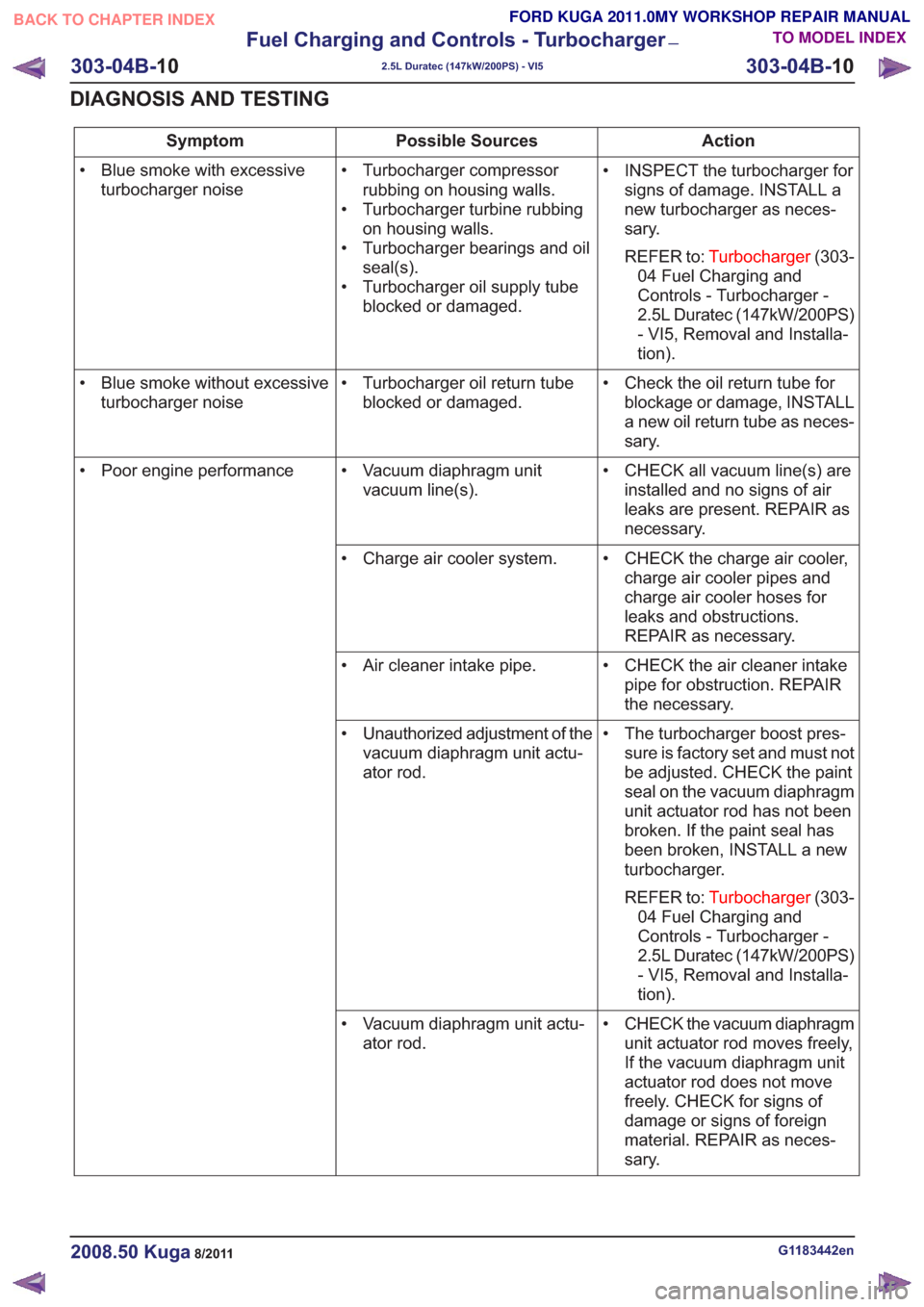
Action
Possible Sources
Symptom
• INSPECT the turbocharger forsigns of damage. INSTALL a
new turbocharger as neces-
sary.
REFER to: Turbocharger (303-
04 Fuel Charging and
Controls - Turbocharger -
2.5L Duratec (147kW/200PS)
- VI5, Removal and Installa-
tion).
• Turbocharger compressor
rubbing on housing walls.
• Turbocharger turbine rubbing on housing walls.
• Turbocharger bearings and oil seal(s).
• Turbocharger oil supply tube blocked or damaged.
• Blue smoke with excessive
turbocharger noise
• Check the oil return tube forblockage or damage, INSTALL
a new oil return tube as neces-
sary.
• Turbocharger oil return tube
blocked or damaged.
• Blue smoke without excessive
turbocharger noise
• CHECK all vacuum line(s) areinstalled and no signs of air
leaks are present. REPAIR as
necessary.
• Vacuum diaphragm unit
vacuum line(s).
• Poor engine performance
• CHECK the charge air cooler,charge air cooler pipes and
charge air cooler hoses for
leaks and obstructions.
REPAIR as necessary.
• Charge air cooler system.
• CHECK the air cleaner intakepipe for obstruction. REPAIR
the necessary.
• Air cleaner intake pipe.
• The turbocharger boost pres-sure is factory set and must not
be adjusted. CHECK the paint
seal on the vacuum diaphragm
unit actuator rod has not been
broken. If the paint seal has
been broken, INSTALL a new
turbocharger.
REFER to: Turbocharger (303-
04 Fuel Charging and
Controls - Turbocharger -
2.5L Duratec (147kW/200PS)
- VI5, Removal and Installa-
tion).
• Unauthorized adjustment of the
vacuum diaphragm unit actu-
ator rod.
• CHECK the vacuum diaphragmunit actuator rod moves freely,
If the vacuum diaphragm unit
actuator rod does not move
freely. CHECK for signs of
damage or signs of foreign
material. REPAIR as neces-
sary.
• Vacuum diaphragm unit actu-
ator rod.
G1183442en2008.50 Kuga8/2011
303-04B- 10
Fuel Charging and Controls - Turbocharger
—
2.5L Duratec (147kW/200PS) - VI5
303-04B- 10
DIAGNOSIS AND TESTING
TO MODEL INDEX
BACK TO CHAPTER INDEX
FORD KUGA 2011.0MY WORKSHOP REPAIR MANUAL
Page 1748 of 2057
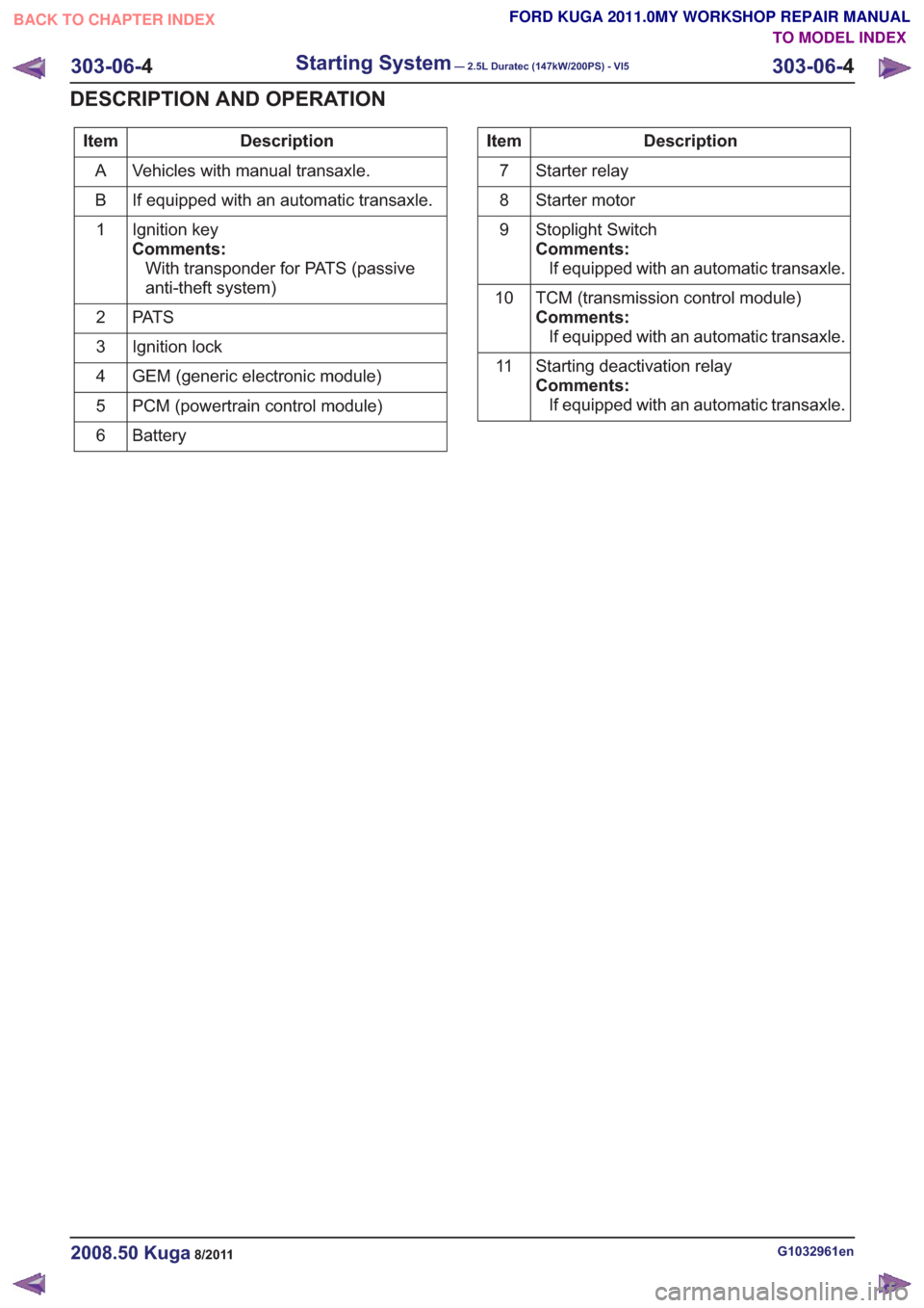
Description
Item
Vehicles with manual transaxle.
A
If equipped with an automatic transaxle.
B
Ignition key
Comments:With transponder for PATS (passive
anti-theft system)
1
PAT S
2
Ignition lock
3
GEM (generic electronic module)
4
PCM (powertrain control module)
5
Battery
6Description
Item
Starter relay
7
Starter motor
8
Stoplight Switch
Comments:If equipped with an automatic transaxle.
9
TCM (transmission control module)
Comments:If equipped with an automatic transaxle.
10
Starting deactivation relay
Comments:If equipped with an automatic transaxle.
11
G1032961en2008.50 Kuga8/2011
303-06-
4
Starting System— 2.5L Duratec (147kW/200PS) - VI5303-06-
4
DESCRIPTION AND OPERATION
TO MODEL INDEX
BACK TO CHAPTER INDEX
FORD KUGA 2011.0MY WORKSHOP REPAIR MANUAL
Page 1750 of 2057
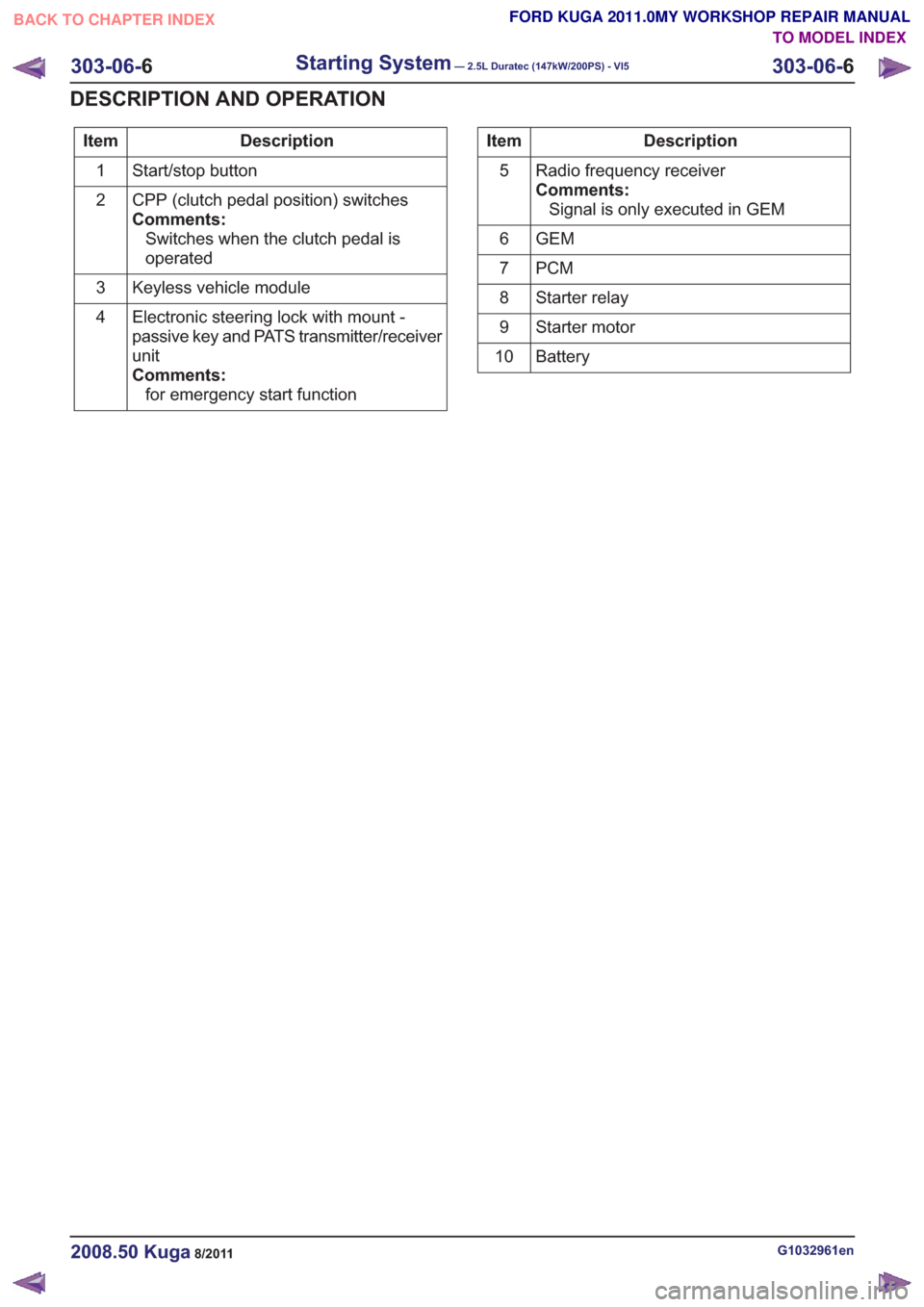
Description
Item
Start/stop button
1
CPP (clutch pedal position) switches
Comments:Switches when the clutch pedal is
operated
2
Keyless vehicle module
3
Electronic steering lock with mount -
passive key and PATS transmitter/receiver
unit
Comments:for emergency start function
4Description
Item
Radio frequency receiver
Comments:Signal is only executed in GEM
5
GEM
6
PCM
7
Starter relay
8
Starter motor
9
Battery
10
G1032961en2008.50 Kuga8/2011
303-06- 6
Starting System— 2.5L Duratec (147kW/200PS) - VI5303-06-
6
DESCRIPTION AND OPERATION
TO MODEL INDEX
BACK TO CHAPTER INDEX
FORD KUGA 2011.0MY WORKSHOP REPAIR MANUAL
Page 1752 of 2057
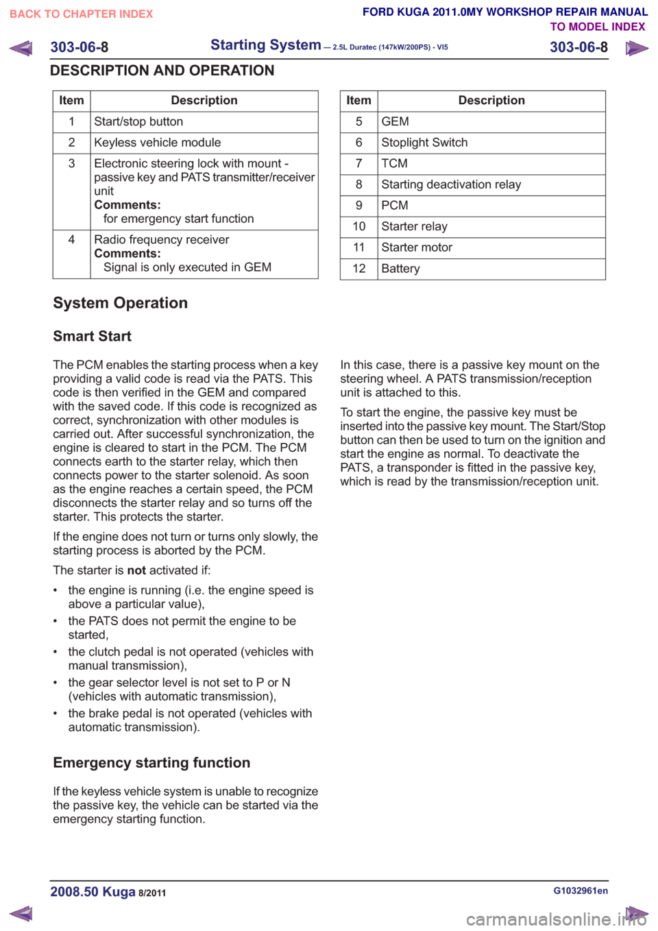
Description
Item
Start/stop button
1
Keyless vehicle module
2
Electronic steering lock with mount -
passive key and PATS transmitter/receiver
unit
Comments:for emergency start function
3
Radio frequency receiver
Comments:Signal is only executed in GEM
4Description
Item
GEM
5
Stoplight Switch
6
TCM7
Starting deactivation relay
8
PCM
9
Starter relay
10
Starter motor
11
Battery
12
System Operation
Smart Start
The PCM enables the starting process when a key
providing a valid code is read via the PATS. This
code is then verified in the GEM and compared
with the saved code. If this code is recognized as
correct, synchronization with other modules is
carried out. After successful synchronization, the
engine is cleared to start in the PCM. The PCM
connects earth to the starter relay, which then
connects power to the starter solenoid. As soon
as the engine reaches a certain speed, the PCM
disconnects the starter relay and so turns off the
starter. This protects the starter.
If the engine does not turn or turns only slowly, the
starting process is aborted by the PCM.
The starter is notactivated if:
• the engine is running (i.e. the engine speed is above a particular value),
• the PATS does not permit the engine to be started,
• the clutch pedal is not operated (vehicles with manual transmission),
• the gear selector level is not set to P or N (vehicles with automatic transmission),
• the brake pedal is not operated (vehicles with automatic transmission).
Emergency starting function
If the keyless vehicle system is unable to recognize
the passive key, the vehicle can be started via the
emergency starting function. In this case, there is a passive key mount on the
steering wheel. A PATS transmission/reception
unit is attached to this.
To start the engine, the passive key must be
inserted into the passive key mount. The Start/Stop
button can then be used to turn on the ignition and
start the engine as normal. To deactivate the
PATS, a transponder is fitted in the passive key,
which is read by the transmission/reception unit.
G1032961en2008.50 Kuga8/2011
303-06-
8
Starting System— 2.5L Duratec (147kW/200PS) - VI5303-06-
8
DESCRIPTION AND OPERATION
TO MODEL INDEX
BACK TO CHAPTER INDEX
FORD KUGA 2011.0MY WORKSHOP REPAIR MANUAL
Page 1763 of 2057
Engine Emission Control
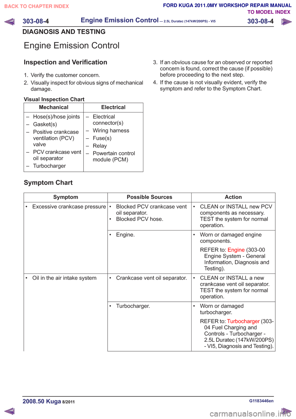
Inspection and Verification
1. Verify the customer concern.
2. Visually inspect for obvious signs of mechanicaldamage.
Visual Inspection Chart
Electrical
Mechanical
– Electricalconnector(s)
– Wiring harness
– Fuse(s)
– Relay
– Powertain control module (PCM)
– Hose(s)/hose joints
– Gasket(s)
– Positive crankcase
ventilation (PCV)
valve
– PCV crankcase vent oil separator
– Turbocharger 3. If an obvious cause for an observed or reported
concern is found, correct the cause (if possible)
before proceeding to the next step.
4. If the cause is not visually evident, verify the symptom and refer to the Symptom Chart.
Symptom Chart
Action
Possible Sources
Symptom
• CLEAN or INSTALL new PCVcomponents as necessary.
TEST the system for normal
operation.
• Blocked PCV crankcase vent
oil separator.
• Blocked PCV hose.
• Excessive crankcase pressure
• Worn or damaged enginecomponents.
REFER to: Engine(303-00
Engine System - General
Information, Diagnosis and
Testing).
• Engine.
• CLEAN or INSTALL a newcrankcase vent oil separator.
TEST the system for normal
operation.
• Crankcase vent oil separator.
• Oil in the air intake system
• Worn or damagedturbocharger.
REFER to: Turbocharger (303-
04 Fuel Charging and
Controls - Turbocharger -
2.5L Duratec (147kW/200PS)
- VI5, Diagnosis and Testing).
• Turbocharger.
G1183446en2008.50 Kuga8/2011
303-08-
4
Engine Emission Control— 2.5L Duratec (147kW/200PS) - VI5303-08-
4
DIAGNOSIS AND TESTING
TO MODEL INDEX
BACK TO CHAPTER INDEX
FORD KUGA 2011.0MY WORKSHOP REPAIR MANUAL
Page 1768 of 2057
Intake Air Distribution and Filtering
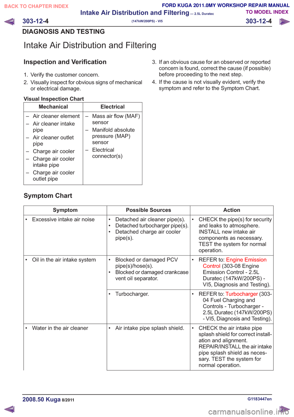
Inspection and Verification
1. Verify the customer concern.
2. Visually inspect for obvious signs of mechanicalor electrical damage.
Visual Inspection Chart
Electrical
Mechanical
– Mass air flow (MAF)sensor
– Manifold absolute pressure (MAP)
sensor
– Electrical connector(s)
– Air cleaner element
– Air cleaner intake
pipe
– Air cleaner outlet pipe
– Charge air cooler
– Charge air cooler intake pipe
– Charge air cooler outlet pipe 3. If an obvious cause for an observed or reported
concern is found, correct the cause (if possible)
before proceeding to the next step.
4. If the cause is not visually evident, verify the symptom and refer to the Symptom Chart.
Symptom Chart
Action
Possible Sources
Symptom
• CHECK the pipe(s) for securityand leaks to atmosphere.
INSTALL new intake air
components as necessary.
TEST the system for normal
operation.
• Detached air cleaner pipe(s).
• Detached turbocharger pipe(s).
• Detached charge air cooler
pipe(s).
• Excessive intake air noise
• REFER to:Engine Emission
Control (303-08 Engine
Emission Control - 2.5L
Duratec (147kW/200PS) -
VI5, Diagnosis and Testing).
• Blocked or damaged PCV
pipe(s)/hose(s).
• Blocked or damaged crankcase vent oil separator.
• Oil in the air intake system
• REFER to:Turbocharger(303-
04 Fuel Charging and
Controls - Turbocharger -
2.5L Duratec (147kW/200PS)
- VI5, Diagnosis and Testing).
• Turbocharger.
• CHECK the air intake pipesplash shield for correct install-
ation and alignment.
REPAIR/INSTALL the air intake
pipe splash shield as neces-
sary. TEST the system for
normal operation.
• Air intake pipe splash shield.
• Water in the air cleaner
G1183447en2008.50 Kuga8/2011
303-12- 4
Intake Air Distribution and Filtering
— 2.5L Duratec
(147kW/200PS) - VI5
303-12- 4
DIAGNOSIS AND TESTING
TO MODEL INDEX
BACK TO CHAPTER INDEX
FORD KUGA 2011.0MY WORKSHOP REPAIR MANUAL
Page 1769 of 2057
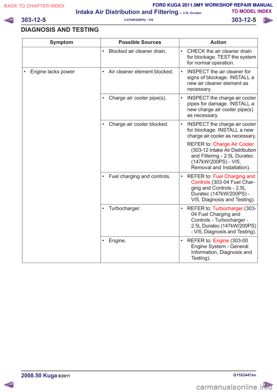
Action
Possible Sources
Symptom
• CHECK the air cleaner drainfor blockage. TEST the system
for normal operation.
• Blocked air cleaner drain.
• INSPECT the air cleaner forsigns of blockage. INSTALL a
new air cleaner element as
necessary.
• Air cleaner element blocked.
• Engine lacks power
• INSPECT the charge air coolerpipes for damage. INSTALL a
new charge air cooler pipe(s)
as necessary.
• Charge air cooler pipe(s).
• INSPECT the charge air coolerfor blockage. INSTALL a new
charge air cooler as necessary.
REFER to: Charge Air Cooler
(303-12 Intake Air Distribution
and Filtering - 2.5L Duratec
(147kW/200PS) - VI5,
Removal and Installation).
• Charge air cooler blocked.
• REFER to:Fuel Charging and
Controls (303-04 Fuel Char-
ging and Controls - 2.5L
Duratec (147kW/200PS) -
VI5, Diagnosis and Testing).
• Fuel charging and controls.
• REFER to:Turbocharger(303-
04 Fuel Charging and
Controls - Turbocharger -
2.5L Duratec (147kW/200PS)
- VI5, Diagnosis and Testing).
• Turbocharger.
• REFER to:Engine(303-00
Engine System - General
Information, Diagnosis and
Testing).
• Engine.
G1183447en2008.50 Kuga8/2011
303-12-
5
Intake Air Distribution and Filtering
— 2.5L Duratec
(147kW/200PS) - VI5
303-12- 5
DIAGNOSIS AND TESTING
TO MODEL INDEX
BACK TO CHAPTER INDEX
FORD KUGA 2011.0MY WORKSHOP REPAIR MANUAL