2011 FORD KUGA lock
[x] Cancel search: lockPage 1781 of 2057
Electronic Engine Controls – Overview
General overview
Engine Management System
• Bosch ME 9.0 engine management system
• Knock control with two knock sensors
• Electronic Throttle Control Unit.
• Electronic accelerator pedal
• Variable camshaft timing for intake and exhaustcamshafts • Fuel injection supply manifold with combined
fuel pressure and temperature sensor
• Sequential multi-port fuel injection
• Camshaft position (CMP) sensors for intake and exhaust camshafts.
• satisfies the European exhaust emissions standard IV
• EOBD (European On-board Diagnostic) for the monitoring of emissions-related components.
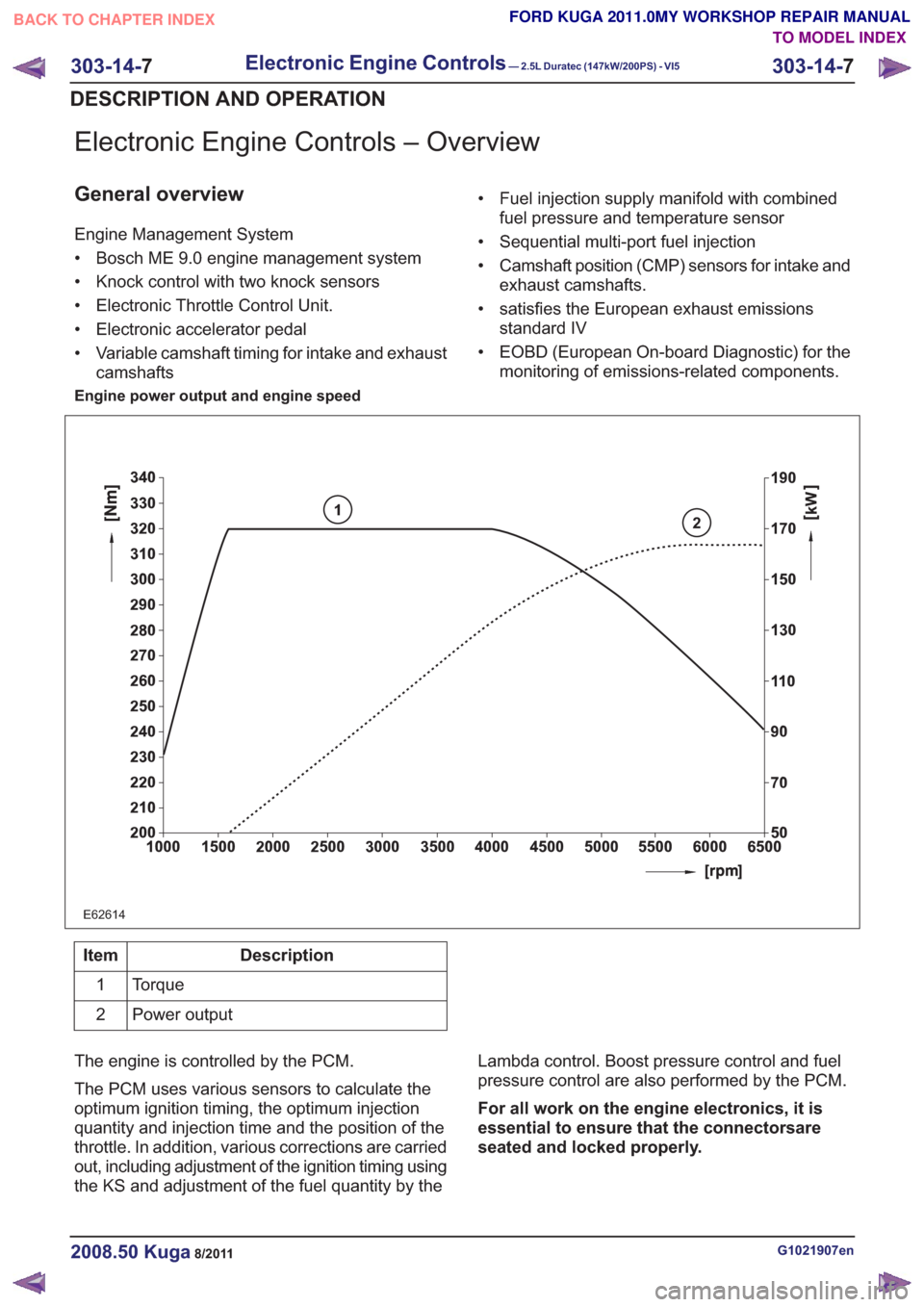
Engine power output and engine speed
2
E62614
1
Description
Item
Torque
1
Power output
2
The engine is controlled by the PCM.
The PCM uses various sensors to calculate the
optimum ignition timing, the optimum injection
quantity and injection time and the position of the
throttle. In addition, various corrections are carried
out, including adjustment of the ignition timing using
the KS and adjustment of the fuel quantity by the Lambda control. Boost pressure control and fuel
pressure control are also performed by the PCM.
For all work on the engine electronics, it is
essential to ensure that the connectorsare
seated and locked properly.
G1021907en2008.50 Kuga8/2011
303-14-
7
Electronic Engine Controls— 2.5L Duratec (147kW/200PS) - VI5303-14-
7
DESCRIPTION AND OPERATION
TO MODEL INDEX
BACK TO CHAPTER INDEX
FORD KUGA 2011.0MY WORKSHOP REPAIR MANUAL
Page 1782 of 2057
Powertrain Control Module (PCM)
E65160
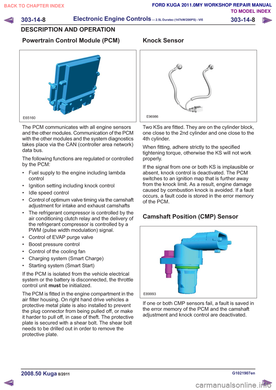
The PCM communicates with all engine sensors
and the other modules. Communication of the PCM
with the other modules and the system diagnostics
takes place via the CAN (controller area network)
data bus.
The following functions are regulated or controlled
by the PCM:
• Fuel supply to the engine including lambdacontrol
• Ignition setting including knock control
• Idle speed control
• Control of optimum valve timing via the camshaft adjustment for intake and exhaust camshafts
• The refrigerant compressor is controlled by the air conditioning clutch relay and the delivery of
the refrigerant compressor is controlled by a
PWM (pulse width modulation) signal.
• Control of EVAP purge valve
• Boost pressure control
• Control of the cooling fan
• Charging system (Smart Charge)
• Starting system (Smart Start)
If the PCM is isolated from the vehicle electrical
system or the battery is disconnected, the throttle
control unit mustbe initialized.
The PCM is fitted in the engine compartment in the
air filter housing. On right hand drive vehicles a
protective metal plate is also installed to prevent
the plug connector from being pulled off, or make
it harder to pull off, in case of theft. The protective
plate is secured with a shear bolt. The shear bolt
needs to be drilled out in order to remove the
protective plate.
Knock Sensor
E96986
Two KSs are fitted. They are on the cylinder block,
one close to the 2nd cylinder and one close to the
4th cylinder.
When fitting, adhere strictly to the specified
tightening torque, otherwise the KS will not work
properly.
If the signal from one or both KS is implausible or
absent, knock control is deactivated. The PCM
switches to an ignition map that is further away
from the knock limit. As a result, engine damage
caused by combustion knock is avoided. If a fault
occurs, a fault code is stored in the error memory
of the PCM.
Camshaft Position (CMP) Sensor
E89993
If one or both CMP sensors fail, a fault is saved in
the error memory of the PCM and the camshaft
adjustment and knock control are deactivated.
G1021907en2008.50 Kuga8/2011
303-14- 8
Electronic Engine Controls— 2.5L Duratec (147kW/200PS) - VI5303-14-
8
DESCRIPTION AND OPERATION
TO MODEL INDEX
BACK TO CHAPTER INDEX
FORD KUGA 2011.0MY WORKSHOP REPAIR MANUAL
Page 1797 of 2057
Calculation of valve timing adjustment
angle
The 2.5L Duratec (VI5) engine has two camshaft
adjustment units which work independently of each
other.
One camshaft adjustment solenoid is installed for
each intake camshaft and exhaust camshaft.
This allows the PCM to continuously adjust the
intake and exhaust-side camshaft adjustments
independently of one another. The timing is
adjusted by the PCM using curves; adjustment is
primarily done as a function of engine load and
engine speed.
In this way the engine performance is increased
and internal exhaust gas recirculation is realized.
The advantages of camshaft adjustment are as
follows:
• Higher torque and improved torquecharacteristics
• Reduced fuel consumption
• Improved emissions performance
The camshaft adjustment solenoids are actuated
by the PWM by means of a PCM signal.
Continuous adjustment of the camshafts by the
PCM is achieved by means of the camshaft
adjustment solenoids, the camshaft adjustment
units and two CMP sensors. A defined quantity of
engine is oil is supplied to or drained from the
adjustment units via the camshaft adjustment
solenoids. The existing EOP (engine oil pressure)
is taken into account in the process. In this way
the valve timings are adjusted according to the
operating condition of the engine. The camshaft
adjusters work according to the vane-cell principle.
On starting the engine, both camshafts are
mechanically locked in their starting positions. The
intake camshaft is in the maximum late position
and the exhaust camshaft in the maximum early
position.
Control is divided into four main areas:
• Low engine speed and low load
• Partial load
• Low engine speed and high load
• High engine speed and high load
At low engine speed and low load, the exhaust
valves open early and the intake valves open late.
The result is reduced fuel consumption and more
uniform idling. In the partial load range, the exhaust valves and
the intake valves open late. The late opening of
the exhaust valves results in a good utilization of
the expanding gases in the cylinder. Closing the
exhaust valves after Top Dead Center allows
internal exhaust gas recirculation through aspiration
of exhaust gases into the combustion chamber.
Moreover, the intake valves close after Bottom
Dead Centre, allowing the fresh air/fuel mixture
and exhaust gases to flow back into the intake
tract. The result is reduced fuel consumption and
low emissions.
At low engine speed and high engine load, the
exhaust valves open late and the intake valves
open early. Due to the resulting valve opening
overlap at Top Dead Centre, the pulsating gas
column within the combustion chamber is utilized
to achieve better charging of the combustion
chamber. The result is increased torque at lower
RPM.
At high engine speeds and high engine load, the
exhaust valves open early and the intake valves
close late. Because a rapid gas exchange must be
achieved at high engine speeds, the early opening
of the exhaust valves achieves better expulsion of
the exhaust gas and the late closing of the intake
valves improves cylinder charge efficiency.
Optimum power output is achieved.
Many other camshaft positions are possible in
addition to these settings.
In order to avoid a malfunction in the camshaft
adjustment units at excessively low ambient or
engine-oil temperatures, they are activated by the
PCM with a time delay via the camshaft adjustment
solenoids. The PCM receives the information
required for this from the ECT sensor and the
outside air temperature sensor.
When idling and during deceleration, the camshaft
adjustment solenoids are activated repeatedly by
the PCM in order to remove any dirt which may be
on the bore holes and ring grooves.
Boost pressure control
Optimum regulation is achieved by means of an
electronically-controlled solenoid valve, the boost
control solenoid valve.
Refer to:
Turbocharger (303-04 Fuel Charging and
Controls - Turbocharger - 2.5L Duratec
(147kW/200PS) - VI5, Description and
Operation).
G1021908en2008.50 Kuga8/2011
303-14- 23
Electronic Engine Controls— 2.5L Duratec (147kW/200PS) - VI5303-14-
23
DESCRIPTION AND OPERATION
TO MODEL INDEX
BACK TO CHAPTER INDEX
FORD KUGA 2011.0MY WORKSHOP REPAIR MANUAL
Page 1799 of 2057
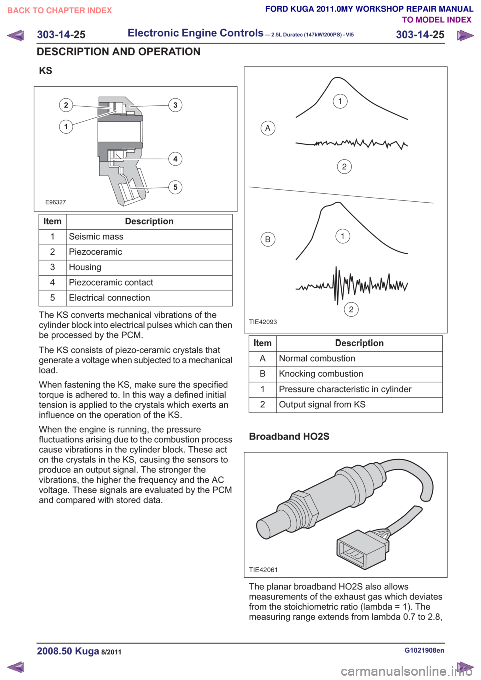
KS
E96327
23
5
4
1
Description
Item
Seismic mass
1
Piezoceramic
2
Housing
3
Piezoceramic contact
4
Electrical connection
5
The KS converts mechanical vibrations of the
cylinder block into electrical pulses which can then
be processed by the PCM.
The KS consists of piezo-ceramic crystals that
generate a voltage when subjected to a mechanical
load.
When fastening the KS, make sure the specified
torque is adhered to. In this way a defined initial
tension is applied to the crystals which exerts an
influence on the operation of the KS.
When the engine is running, the pressure
fluctuations arising due to the combustion process
cause vibrations in the cylinder block. These act
on the crystals in the KS, causing the sensors to
produce an output signal. The stronger the
vibrations, the higher the frequency and the AC
voltage. These signals are evaluated by the PCM
and compared with stored data.
TIE42093
1
2
A
B1
2
Description
Item
Normal combustion
A
Knocking combustion
B
Pressure characteristic in cylinder
1
Output signal from KS
2
Broadband HO2S
TIE42061
The planar broadband HO2S also allows
measurements of the exhaust gas which deviates
from the stoichiometric ratio (lambda = 1). The
measuring range extends from lambda 0.7 to 2.8,
G1021908en2008.50 Kuga8/2011
303-14- 25
Electronic Engine Controls— 2.5L Duratec (147kW/200PS) - VI5303-14-
25
DESCRIPTION AND OPERATION
TO MODEL INDEX
BACK TO CHAPTER INDEX
FORD KUGA 2011.0MY WORKSHOP REPAIR MANUAL
Page 1823 of 2057
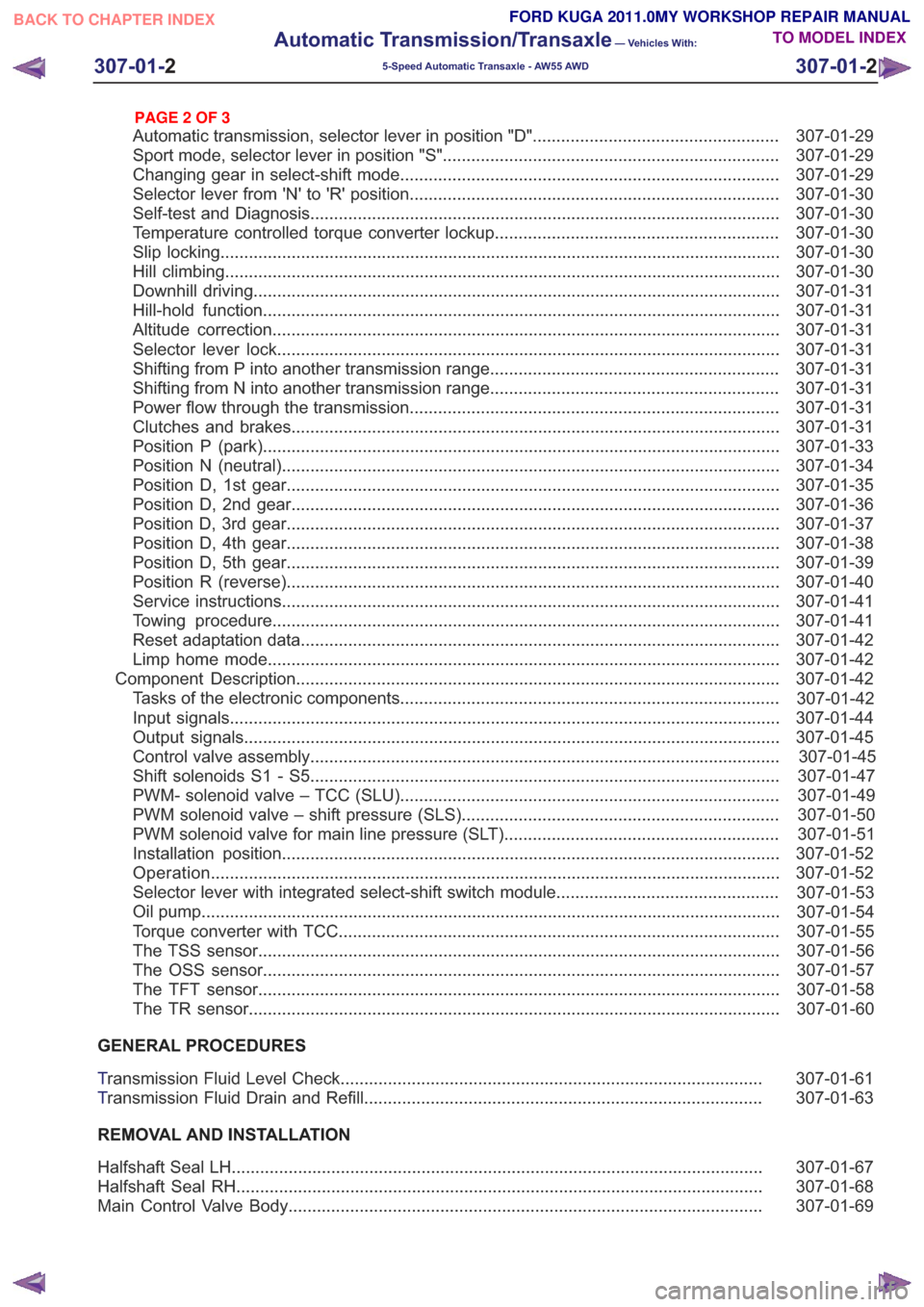
307-01-29
Automatic transmission, selector lever in position "D". ...................................................
307-01-29
Sport mode, selector lever in position "S" .......................................................................
307-01-29
Changing gear in select-shift mode........................................................................\
........
307-01-30
Selector lever from 'N' to 'R' position ........................................................................\
......
307-01-30
Self-test and Diagnosis ........................................................................\
...........................
307-01-30
Temperature controlled torque converter lockup ............................................................
307-01-30
Slip locking ........................................................................\
..............................................
307-01-30
Hill climbing ........................................................................\
.............................................
307-01-31
Downhill driving ........................................................................\
.......................................
307-01-31
Hill-hold function ........................................................................\
.....................................
307-01-31
Altitude correction ........................................................................\
...................................
307-01-31
Selector lever lock ........................................................................\
..................................
307-01-31
Shifting from P into another transmission range .............................................................
307-01-31
Shifting from N into another transmission range .............................................................
307-01-31
Power flow through the transmission ........................................................................\
......
307-01-31
Clutches and brakes ........................................................................\
...............................
307-01-33
Position P (park) ........................................................................\
.....................................
307-01-34
Position N (neutral) ........................................................................\
.................................
307-01-35
Position D, 1st gear........................................................................\
................................
307-01-36
Position D, 2nd gear ........................................................................\
...............................
307-01-37
Position D, 3rd gear ........................................................................\
................................
307-01-38
Position D, 4th gear ........................................................................\
................................
307-01-39
Position D, 5th gear ........................................................................\
................................
307-01-40
Position R (reverse) ........................................................................\
................................
307-01-41
Service instructions ........................................................................\
.................................
307-01-41
Towing procedure ........................................................................\
...................................
307-01-42
Reset adaptation data ........................................................................\
.............................
307-01-42
Limp home mode ........................................................................\
....................................
307-01-42
Component Description ........................................................................\
..............................
Tasks of the electronic components ........................................................................\
........
307-01-44
Input signals ........................................................................\
............................................
307-01-45
Output signals ........................................................................\
.........................................
Control valve assembly ........................................................................\
...........................
Shift solenoids S1 - S5 ........................................................................\
...........................
PWM-
solenoid valve – TCC (SLU) ........................................................................\
........
PWM solenoid valve – shift pressure (SLS) ...................................................................
PWM solenoid valve for main line pressure (SLT) ..........................................................
307-01-52
Installation position ........................................................................\
.................................
Operation ........................................................................\
................................................
Selector lever with integrated select-shift switch module ...............................................
Oil pump ........................................................................\
..................................................
Torque converter with TCC ........................................................................\
.....................
The TSS sensor ........................................................................\
......................................
The OSS sensor ........................................................................\
.....................................
The TFT sensor ........................................................................\
......................................
The TR sensor ........................................................................\
........................................
GENERAL PROCEDURES
T ransmission Fluid Level Check ........................................................................\
.................
307-01-63
T ransmission Fluid Drain and Refill ........................................................................\
............
REMOVAL AND INSTALLATION 307-01-67
Halfshaft Seal LH ........................................................................\
........................................
307-01-68
Halfshaft Seal RH........................................................................\
.......................................
307-01-69
Main Control Valve Body ........................................................................\
............................
307-01-2
Automatic Transmission/Transaxle
— Vehicles With:
5-Speed Automatic Transaxle - AW55 AWD
307-01- 2
.
TO MODEL INDEX
BACK TO CHAPTER INDEX
307-01-42
307-01-49
307-01-52 307-01-47
307-01-45
307-01-50
307-01-51
307-01-53
307-01-55
307-01-54
307-01-56
307-01-57
307-01-58
307-01-61 307-01-60
PAGE 2 OF 3 FORD KUGA 2011.0MY WORKSHOP REPAIR MANUAL
Page 1830 of 2057
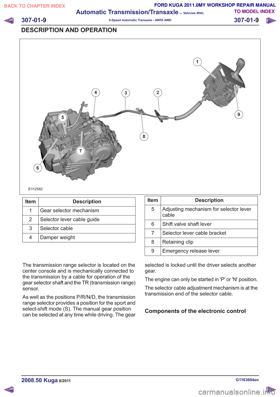
1
234
5
6
8
9
7
E112582
Description
Item
Gear selector mechanism
1
Selector lever cable guide
2
Selector cable
3
Damper weight
4Description
Item
Adjusting mechanism for selector lever
cable
5
Shift valve shaft lever
6
Selector lever cable bracket
7
Retaining clip
8
Emergency release lever
9
The transmission range selector is located on the
center console and is mechanically connected to
the transmission by a cable for operation of the
gear selector shaft and the TR (transmission range)
sensor.
As well as the positions P/R/N/D, the transmission
range selector provides a position for the sport and
select-shift mode (S). The manual gear position
can be selected at any time while driving. The gear selected is locked until the driver selects another
gear.
The engine can only be started in 'P' or 'N' position.
The selector cable adjustment mechanism is at the
transmission end of the selector cable.
Components of the electronic control
G1163604en2008.50 Kuga8/2011
307-01-
9
Automatic Transmission/Transaxle
— Vehicles With:
5-Speed Automatic Transaxle - AW55 AWD
307-01- 9
DESCRIPTION AND OPERATION
TO MODEL INDEX
BACK TO CHAPTER INDEX
FORD KUGA 2011.0MY WORKSHOP REPAIR MANUAL
Page 1831 of 2057
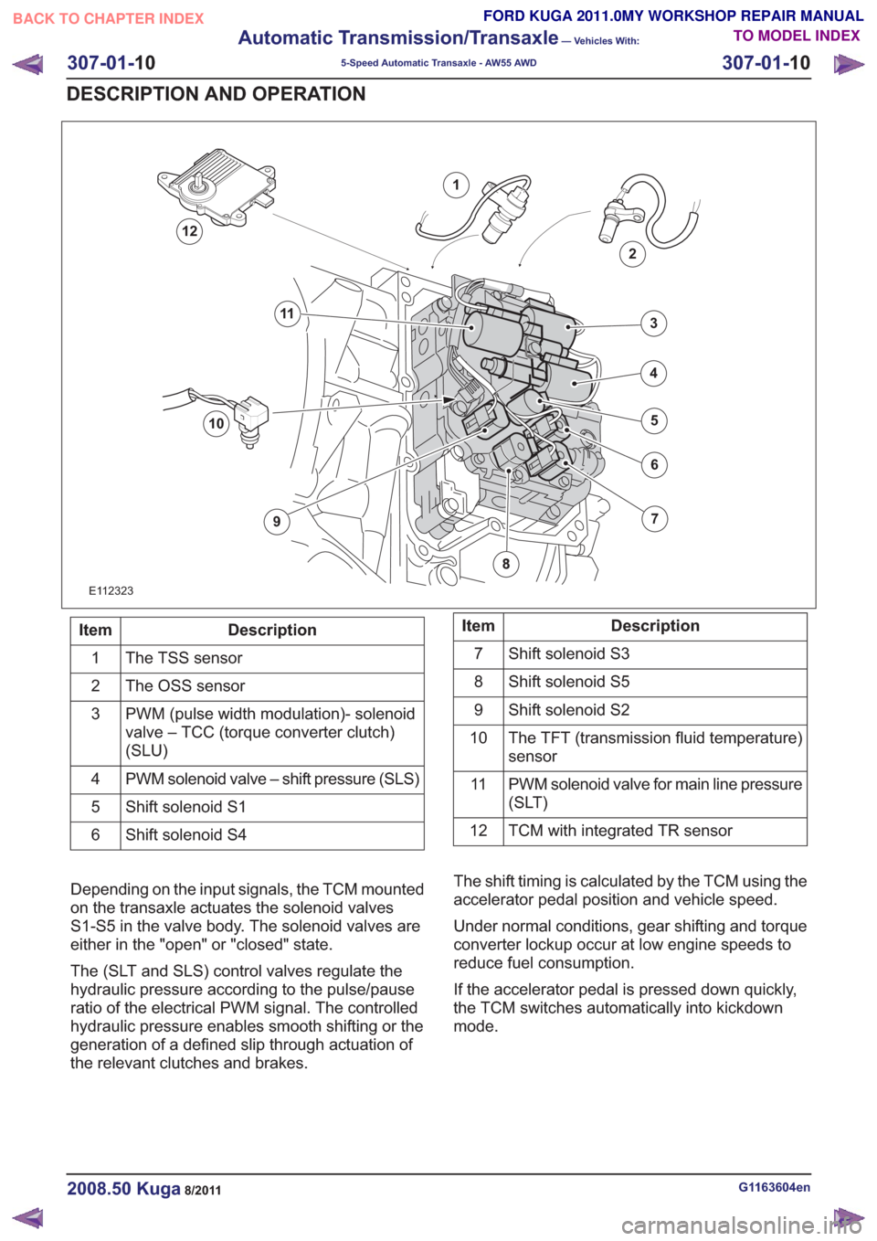
E112323
1
2
7
6
4
5
3
10
9
11
12
Description
Item
The TSS sensor
1
The OSS sensor
2
PWM (pulse width modulation)- solenoid
valve – TCC (torque converter clutch)
(SLU)
3
PWM solenoid valve – shift pressure (SLS)
4
Shift solenoid S1
5
Shift solenoid S4
6Description
Item
Shift solenoid S3
7
Shift solenoid S5
8
Shift solenoid S2
9
The TFT (transmission fluid temperature)
sensor
10
PWM solenoid valve for main line pressure
(SLT)
11
TCM with integrated TR sensor
12
Depending on the input signals, the TCM mounted
on the transaxle actuates the solenoid valves
S1-S5 in the valve body. The solenoid valves are
either in the "open" or "closed" state.
The (SLT and SLS) control valves regulate the
hydraulic pressure according to the pulse/pause
ratio of the electrical PWM signal. The controlled
hydraulic pressure enables smooth shifting or the
generation of a defined slip through actuation of
the relevant clutches and brakes. The shift timing is calculated by the TCM using the
accelerator pedal position and vehicle speed.
Under normal conditions, gear shifting and torque
converter lockup occur at low engine speeds to
reduce fuel consumption.
If the accelerator pedal is pressed down quickly,
the TCM switches automatically into kickdown
mode.
G1163604en2008.50 Kuga8/2011
307-01-
10
Automatic Transmission/Transaxle
— Vehicles With:
5-Speed Automatic Transaxle - AW55 AWD
307-01- 10
DESCRIPTION AND OPERATION
TO MODEL INDEX
BACK TO CHAPTER INDEX
FORD KUGA 2011.0MY WORKSHOP REPAIR MANUAL
Page 1832 of 2057
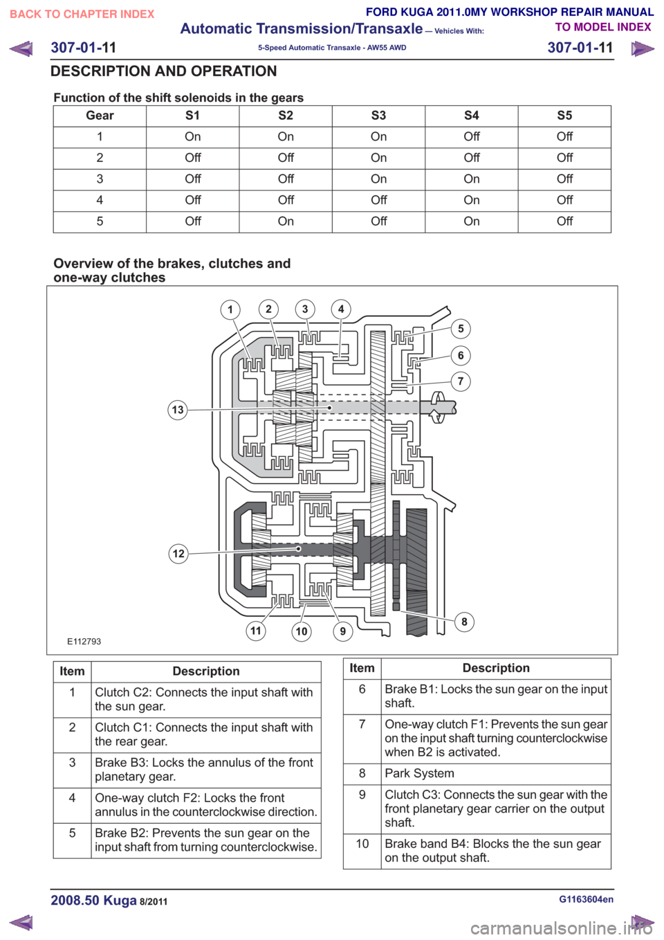
Function of the shift solenoids in the gears
S5
S4
S3
S2
S1
Gear
Off
Off
On
On
On
1
Off
Off
On
Off
Off
2
Off
On
On
Off
Off
3
Off
On
Off
Off
Off
4
Off
On
Off
On
Off
5
Overview of the brakes, clutches and
one-way clutches
E112793
1234
5
12
13
Description
Item
Clutch C2: Connects the input shaft with
the sun gear.
1
Clutch C1: Connects the input shaft with
the rear gear.
2
Brake B3: Locks the annulus of the front
planetary gear.
3
One-way clutch F2: Locks the front
annulus in the counterclockwise direction.
4
Brake B2: Prevents the sun gear on the
input shaft from turning counterclockwise.
5Description
Item
Brake B1: Locks the sun gear on the input
shaft.
6
One-way clutch F1: Prevents the sun gear
on the input shaft turning counterclockwise
when B2 is activated.
7
Park System
8
Clutch C3: Connects the sun gear with the
front planetary gear carrier on the output
shaft.
9
Brake band B4: Blocks the the sun gear
on the output shaft.
10
G1163604en2008.50 Kuga8/2011
307-01-
11
Automatic Transmission/Transaxle
— Vehicles With:
5-Speed Automatic Transaxle - AW55 AWD
307-01- 11
DESCRIPTION AND OPERATION
TO MODEL INDEX
BACK TO CHAPTER INDEX
FORD KUGA 2011.0MY WORKSHOP REPAIR MANUAL