Page 1492 of 2057
All vehicles
16.Refer to: Front Toe Adjustment (204-00
Suspension System - General Information,
General Procedures).
G1001271en2008.50 Kuga8/2011
211-02- 35
Power Steering
211-02- 35
REMOVAL AND INSTALLATION
TO MODEL INDEX
BACK TO CHAPTER INDEX
FORD KUGA 2011.0MY WORKSHOP REPAIR MANUAL
Page 1498 of 2057
Tie Rod End(13 273 0)
Special Tool(s)211-020
Separator, Ball Joint
13006
Removal
NOTE:Removal steps in this procedure may
contain installation details.
1. Refer to: Wheel and Tire (204-04 Wheels and
Tires, Removal and Installation).
2. CAUTION: Make sure that the ball joint ball does not rotate.
1. Torque: 69Nm
2. Torque: 48Nm
E69553
2
1
3.Special Tool(s): 211-020
E69554
211-020
4. NOTE: Make sure that the tie rod end is
installed with the same number of turns as when
removed.
E69728
Installation
1. To install, reverse the removal procedure.
2. Refer to: Front Toe Adjustment (204-00
Suspension System - General Information,
General Procedures).
G1001768en2008.50 Kuga8/2011
211-03- 2
Steering Linkage
211-03- 2
REMOVAL AND INSTALLATION
TO MODEL INDEX
BACK TO CHAPTER INDEX
FORD KUGA 2011.0MY WORKSHOP REPAIR MANUAL
Page 1501 of 2057
Steering Gear Boot(13 134 0)
Special Tool(s)204-169
Clamping Tool, Boot
Retaining Clamp
14044
Removal
NOTE:Removal steps in this procedure may
contain installation details.
1. Refer to: Tie Rod End (211-03 Steering Linkage,
Removal and Installation).
2.
E99467
Installation
1. To install, reverse the removal procedure.
2. Special Tool(s): 204-169
E69906
204-169
3.Refer to: Front Toe Adjustment (204-00
Suspension System - General Information,
General Procedures).
G1001769en2008.50 Kuga8/2011
211-03- 5
Steering Linkage
211-03- 5
REMOVAL AND INSTALLATION
TO MODEL INDEX
BACK TO CHAPTER INDEX
FORD KUGA 2011.0MY WORKSHOP REPAIR MANUAL
Page 1506 of 2057
Steering Column(13 542 0)
Removal
WARNINGS:
The supplemental restraint system (SRS)
is active for a certain length of time after
the power supply has been disconnected.
Wait for a minimum of 3 minutes before
disconnecting or removing any SRS
components.
Make sure that the vehicle electrical
system is fully depowered and no other
power source is connected.
NOTE: Removal steps in this procedure may
contain installation details.
1. NOTE: Make sure that the road wheels are in
the straight ahead position.
E99259
2. CAUTION: Make sure that the steering wheel lock is engaged.
Refer to: Battery Disconnect and Connect
(414-01 Battery, Mounting and Cables,
General Procedures).
3. If equipped.
E100834
4.
E95563
5.
E99639
1
2
6.
E99720
G1058718en2008.50 Kuga8/2011
211-04- 5
Steering Column
211-04- 5
REMOVAL AND INSTALLATION
TO MODEL INDEX
BACK TO CHAPTER INDEX
FORD KUGA 2011.0MY WORKSHOP REPAIR MANUAL
Page 1524 of 2057

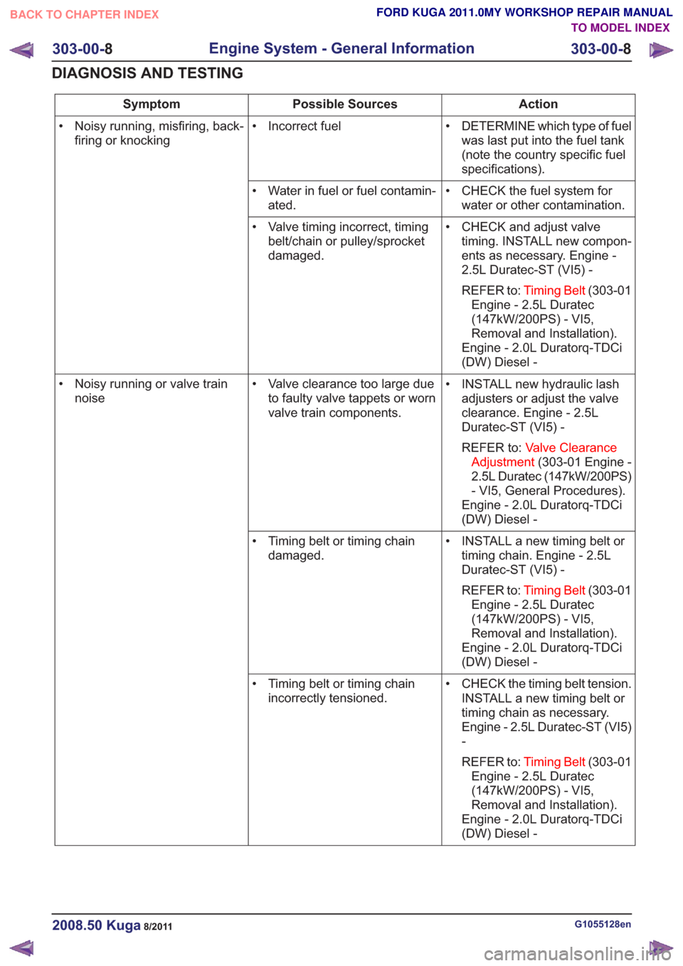
Action
Possible Sources
Symptom
• DETERMINE which type of fuelwas last put into the fuel tank
(note the country specific fuel
specifications).
• Incorrect fuel
• Noisy running, misfiring, back-
firing or knocking
• CHECK the fuel system forwater or other contamination.
• Water in fuel or fuel contamin-
ated.
• CHECK and adjust valvetiming. INSTALL new compon-
ents as necessary. Engine -
2.5L Duratec-ST (VI5) -
REFER to: Timing Belt (303-01
Engine - 2.5L Duratec
(147kW/200PS) - VI5,
Removal and Installation).
Engine - 2.0L Duratorq-TDCi
(DW) Diesel -
• Valve timing incorrect, timing
belt/chain or pulley/sprocket
damaged.
• INSTALL new hydraulic lashadjusters or adjust the valve
clearance. Engine - 2.5L
Duratec-ST (VI5) -
REFER to: Valve Clearance
Adjustment (303-01 Engine -
2.5L Duratec (147kW/200PS)
- VI5, General Procedures).
Engine - 2.0L Duratorq-TDCi
(DW) Diesel -
• Valve clearance too large due
to faulty valve tappets or worn
valve train components.
• Noisy running or valve train
noise
• INSTALL a new timing belt ortiming chain. Engine - 2.5L
Duratec-ST (VI5) -
REFER to: Timing Belt (303-01
Engine - 2.5L Duratec
(147kW/200PS) - VI5,
Removal and Installation).
Engine - 2.0L Duratorq-TDCi
(DW) Diesel -
• Timing belt or timing chain
damaged.
• CHECK the timing belt tension.INSTALL a new timing belt or
timing chain as necessary.
Engine - 2.5L Duratec-ST (VI5)
-
REFER to: Timing Belt (303-01
Engine - 2.5L Duratec
(147kW/200PS) - VI5,
Removal and Installation).
Engine - 2.0L Duratorq-TDCi
(DW) Diesel -
• Timing belt or timing chain
incorrectly tensioned.
G1055128en2008.50 Kuga8/2011
303-00- 8
Engine System - General Information
303-00- 8
DIAGNOSIS AND TESTING
TO MODEL INDEX
BACK TO CHAPTER INDEX
FORD KUGA 2011.0MY WORKSHOP REPAIR MANUAL
Page 1526 of 2057

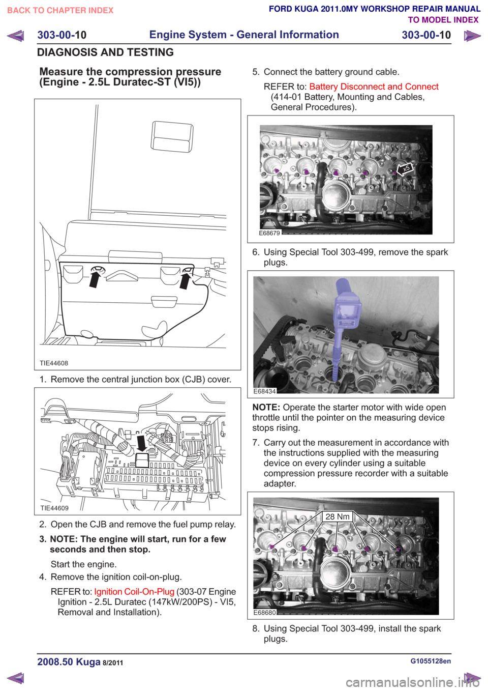
Measure the compression pressure
(Engine - 2.5L Duratec-ST (VI5))
TIE44608
1. Remove the central junction box (CJB) cover.
TIE44609
2. Open the CJB and remove the fuel pump relay.
3. NOTE: The engine will start, run for a fewseconds and then stop.
Start the engine.
4. Remove the ignition coil-on-plug.
REFER to: Ignition Coil-On-Plug (303-07 Engine
Ignition - 2.5L Duratec (147kW/200PS) - VI5,
Removal and Installation). 5. Connect the battery ground cable.
REFER to: Battery Disconnect and Connect
(414-01 Battery, Mounting and Cables,
General Procedures).
E68679
x5
6. Using Special Tool 303-499, remove the spark plugs.
E68434
NOTE: Operate the starter motor with wide open
throttle until the pointer on the measuring device
stops rising.
7. Carry out the measurement in accordance with the instructions supplied with the measuring
device on every cylinder using a suitable
compression pressure recorder with a suitable
adapter.
E68680
28 Nm
8. Using Special Tool 303-499, install the sparkplugs.
G1055128en2008.50 Kuga8/2011
303-00- 10
Engine System - General Information
303-00- 10
DIAGNOSIS AND TESTING
TO MODEL INDEX
BACK TO CHAPTER INDEX
FORD KUGA 2011.0MY WORKSHOP REPAIR MANUAL
Page 1534 of 2057

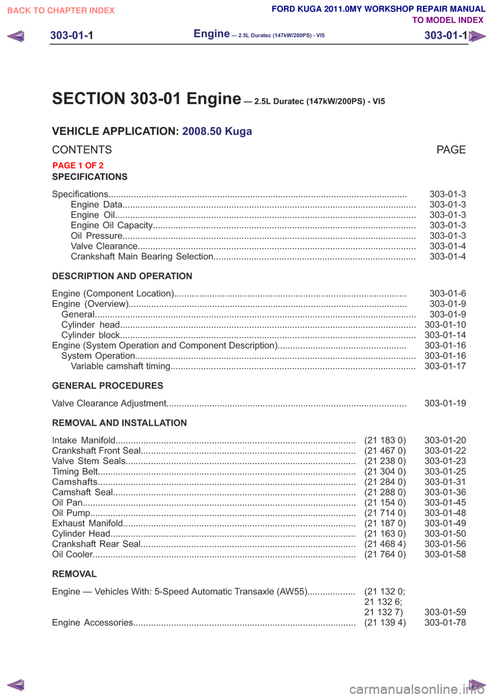
SECTION 303-01 Engine— 2.5L Duratec (147kW/200PS) - VI5
VEHICLE APPLICATION:2008.50 Kuga
PA G E
CONTENTS
SPECIFICATIONS
303-01-3
Specifications ........................................................................\
..............................................
303-01-3
Engine Data ........................................................................\
............................................
303-01-3
Engine Oil ........................................................................\
...............................................
303-01-3
Engine Oil Capacity ........................................................................\
................................
303-01-3
Oil Pressure ........................................................................\
............................................
303-01-4
Valve Clearance ........................................................................\
......................................
303-01-4
Crankshaft Main Bearing Selection ........................................................................\
........
DESCRIPTION AND OPERATION 303-01-6
Engine (Component Location) ........................................................................\
....................
303-01-9
Engine (Overview) ........................................................................\
......................................
303-01-9
General ........................................................................\
.......................................................
303-01-10
Cylinder head ........................................................................\
.............................................
303-01-14
Cylinder block ........................................................................\
.............................................
303-01-16
Engine (System Operation and Component Description) ...................................................
303-01-16
System Operation ........................................................................\
.......................................
303-01-17
Variable camshaft timing ........................................................................\
.........................
GENERAL PROCEDURES 303-01-19
Valve Clearance Adjustment ........................................................................\
.......................
REMOVAL AND INSTALLATION 303-01-20
(21 183 0)
Intake Manifold ........................................................................\
.......................
303-01-22
(21 467 0)
Crankshaft Front Seal ........................................................................\
.............
303-01-23
(21 238 0)
Valve Stem Seals ........................................................................\
...................
303-01-25
(21 304 0)
Timing Belt ........................................................................\
..............................
303-01-31
(21 284 0)
Camshafts ........................................................................\
..............................
303-01-36
(21 288 0)
Camshaft Seal ........................................................................\
........................
303-01-45
(21 154 0)
Oil Pan ........................................................................\
....................................
303-01-48
(21 714 0)
Oil Pump ........................................................................\
.................................
303-01-49
(21 187 0)
Exhaust Manifold ........................................................................\
....................
303-01-50
(21 163 0)
Cylinder Head ........................................................................\
.........................
303-01-56
(21 468 4)
Crankshaft Rear Seal ........................................................................\
.............
303-01-58
(21 764 0)
Oil Cooler ........................................................................\
................................
REMOVAL
303-01-59
(21
132 0;
21 132 6;
21 132 7)
Engine — Vehicles With: 5-Speed Automatic Transaxle (AW55)
...................
303-01-78
(21 139 4)
Engine Accessories ........................................................................\
................
303-01-1
Engine— 2.5L Duratec (147kW/200PS) - VI5303-01-
1
.
TO MODEL INDEX
BACK TO CHAPTER INDEX
PAGE 1 OF 2 FORD KUGA 2011.0MY WORKSHOP REPAIR MANUAL
Page 1552 of 2057
Valve Clearance Adjustment
Special Tool(s)303-1183
Holder, Camshaft
E62756
1.Remove the camshafts.
Refer to: Camshafts (303-01 Engine - 2.5L
Duratec (147kW/200PS) - VI5, Removal and
Installation).
2. CAUTION: Make sure that the valve tappets are installed in their original
locations.
E68493
x20
x5
3.Install only one pair of tappets and the camshaft
for the first measurement.
Special Tool(s): 303-1183
Torque: 17
Nm
E68822
303-1183
4.Measure the valve clearance and if neccessary,
adjust by installing new tappets.
Special Tool(s): 303-1183
Torque: 12
Nm
E66325
303-1183
5.Repeat the measuring procedures for all
cylinders on the intake and on the exhaust side.
G543487en2008.50 Kuga8/2011
303-01- 19
Engine— 2.5L Duratec (147kW/200PS) - VI5303-01-
19
GENERAL PROCEDURES
TO MODEL INDEX
BACK TO CHAPTER INDEX
FORD KUGA 2011.0MY WORKSHOP REPAIR MANUAL