Page 1273 of 2057
All vehicles
14.
E102545
Installation
All vehicles
1.Material: Transmission Oil AWD
(8U7J-8708687-AA) transmission fluid
E102554
Vehicles with 2.0L diesel engine
2. Torque: 25Nm
x4
x2
x4
x2
E102544
G1076971en2008.50 Kuga8/2011
205-02- 28
Rear Drive Axle/Differential
205-02- 28
REMOVAL AND INSTALLATION
TO MODEL INDEX
BACK TO CHAPTER INDEX
FORD KUGA 2011.0MY WORKSHOP REPAIR MANUAL
Page 1274 of 2057
3. CAUTION: Make sure that theinstallation marks are aligned.
2. Torque: 35
E101688
4.Torque: 25Nm
x2
E102531
Vehicles with 2.5L engine
5.Torque: 25
E114254
6. CAUTION: Make sure that the
installation marks are aligned.
1. Torque: 35
2. Torque: 35
3. Torque: 35
E114296
G1076971en2008.50 Kuga8/2011
205-02- 29
Rear Drive Axle/Differential
205-02- 29
REMOVAL AND INSTALLATION
FORD KUGA 2011.0MY WORKSHOP REPAIR MANUAL
TO MODEL INDEX
BACK TO CHAPTER INDEX
1. Torque: 35Nm
Nm
3. Torque: 35Nm
Nm
Nm
Nm
Nm
3
x2
1
2
2
x3
1
E114197
7.
3
1
2
2x3
1
x4
Page 1297 of 2057

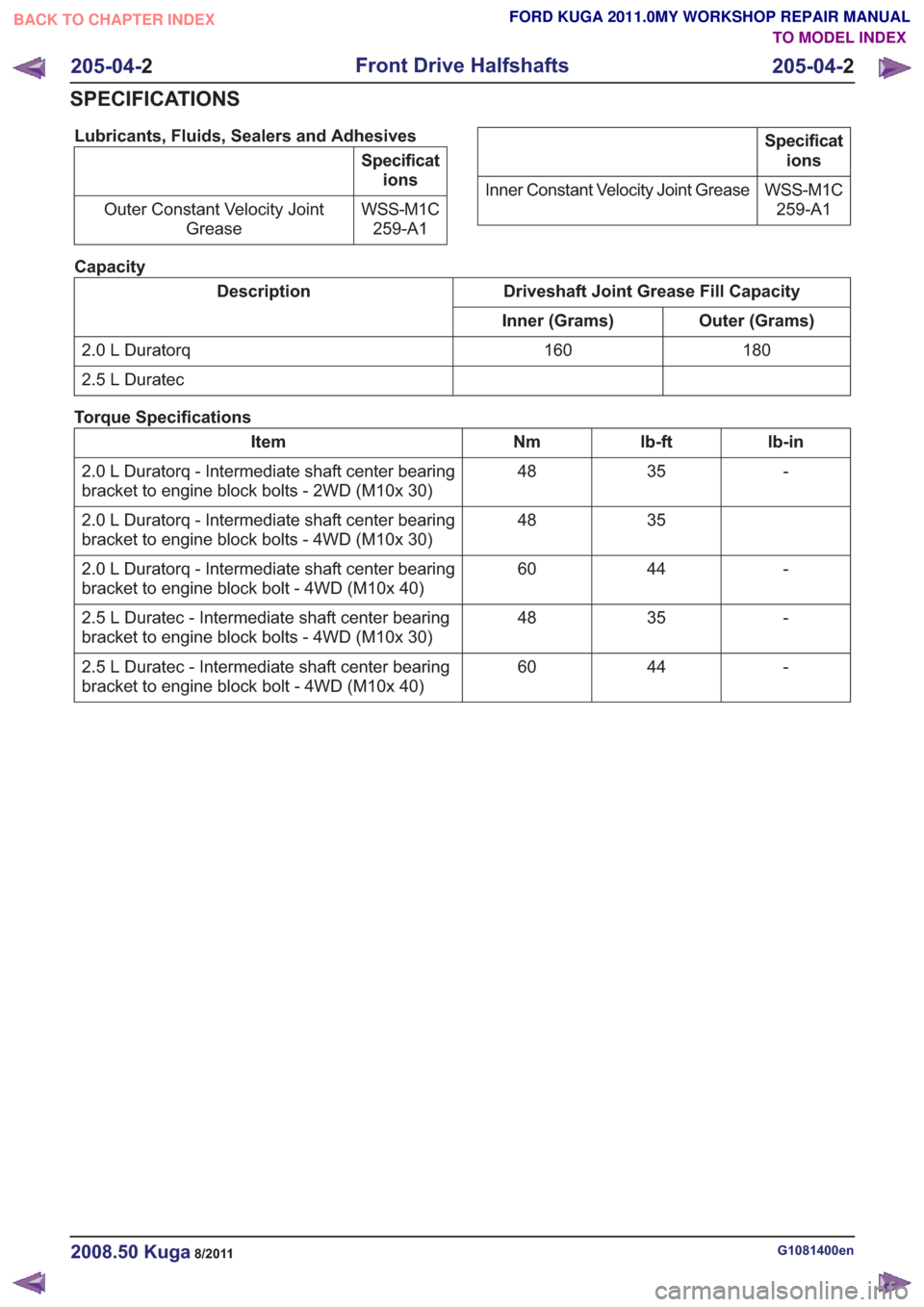
Lubricants, Fluids, Sealers and Adhesives
Specifications
WSS-M1C 259-A1
Outer Constant Velocity Joint
Grease
Specifications
WSS-M1C 259-A1
Inner Constant Velocity Joint Grease
Capacity
Driveshaft Joint Grease Fill Capacity
Description
Outer (Grams)
Inner (Grams)
180
160
2.0 L Duratorq
2.5 L Duratec
Torque Specifications
lb-in
lb-ft
Nm
Item
-
35
48
2.0 L Duratorq - Intermediate shaft center bearing
bracket to engine block bolts - 2WD (M10x 30)
35
48
2.0 L Duratorq - Intermediate shaft center bearing
bracket to engine block bolts - 4WD (M10x 30)
-
44
60
2.0 L Duratorq - Intermediate shaft center bearing
bracket to engine block bolt - 4WD (M10x 40)
-
35
48
2.5 L Duratec - Intermediate shaft center bearing
bracket to engine block bolts - 4WD (M10x 30)
-
44
60
2.5 L Duratec - Intermediate shaft center bearing
bracket to engine block bolt - 4WD (M10x 40)
G1081400en2008.50 Kuga8/2011
205-04- 2
Front Drive Halfshafts
205-04- 2
SPECIFICATIONS
TO MODEL INDEX
BACK TO CHAPTER INDEX
FORD KUGA 2011.0MY WORKSHOP REPAIR MANUAL
Page 1299 of 2057

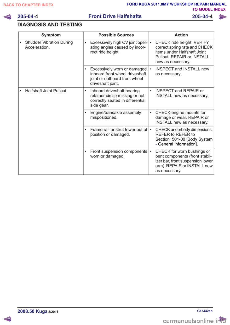
Action
Possible Sources
Symptom
• CHECK ride height, VERIFYcorrect spring rate and CHECK
items under Halfshaft Joint
Pullout. REPAIR or INSTALL
new as necessary.
• Excessively high CV joint oper-
ating angles caused by incor-
rect ride height.
• Shudder Vibration During
Acceleration.
• INSPECT and INSTALL newas necessary.
• Excessively worn or damaged
inboard front wheel driveshaft
joint or outboard front wheel
driveshaft joint.
• INSPECT and REPAIR orINSTALL new as necessary.
• Inboard driveshaft bearing
retainer circlip missing or not
correctly seated in differential
side gear.
• Halfshaft Joint Pullout
• CHECK engine mounts fordamage or wear. REPAIR or
INSTALL new as necessary.
• Engine/transaxle assembly
mispositioned.
• CHECK underbody dimensions.REFER to REFER to
Section 501-00 [Body System
-General Information] .
• Frame rail or strut tower out of
position or damaged.
• CHECK for worn bushings orbent components (front stabil-
izer bar, front suspension lower
arm). REPAIR or INSTALL new
as necessary.
• Front suspension components
worn or damaged.
G17442en2008.50 Kuga8/2011
205-04- 4
Front Drive Halfshafts
205-04- 4
DIAGNOSIS AND TESTING
TO MODEL INDEX
BACK TO CHAPTER INDEX
FORD KUGA 2011.0MY WORKSHOP REPAIR MANUAL
Page 1315 of 2057
Vehicles with 2.5L engine
18.
x2x2
E132332
All vehicles
19. WARNING: Be prepared to collectescaping fluid.
CAUTIONS:
The inner constant velocity (CV) joint
must not be bent more than 18°.
The outer constant velocity (CV) joint
must not be bent more than 45°.
Special Tool(s): 204-159, 204-605
90
204-159
3
4
1
204-605
2
90
204-159
3
4
1
204-605
2
E132335
20. N O T E : This step is only necessary when
installing a new component.
Special Tool(s): 205-071-01
General Equipment: Puller
G1076962en2008.50 Kuga8/2011
205-04- 20
Front Drive Halfshafts
205-04- 20
REMOVAL AND INSTALLATION
TO MODEL INDEX
BACK TO CHAPTER INDEX
FORD KUGA 2011.0MY WORKSHOP REPAIR MANUAL
Page 1319 of 2057
Vehicles with 2.5L engine
5. NOTE:Make sure that a new component is
installed.
Torque: 10
Nm
1.
2. NOTE: Make sure that a new component is
installed.
Torque: 10
Nm
3. Torque: 25Nm
4. Torque: 25Nm
2
4
13
2
4
13
E132331
All vehicles
6. Special Tool(s): 204-605
E102114
204-605
7.Remove the Special Tool(s): 204-609
E102115
204-609
8.
E132381
9.Torque: 83Nm
E102113
10. WARNING: Make sure that a new nut is
installed.
CAUTION: Make sure that the ball joint
ball does not rotate.
Torque: 80
Nm
E99197
11. NOTE: This step is only necessary when
installing a new component.
G1076962en2008.50 Kuga8/2011
205-04- 24
Front Drive Halfshafts
205-04- 24
REMOVAL AND INSTALLATION
TO MODEL INDEX
BACK TO CHAPTER INDEX
FORD KUGA 2011.0MY WORKSHOP REPAIR MANUAL
Page 1344 of 2057

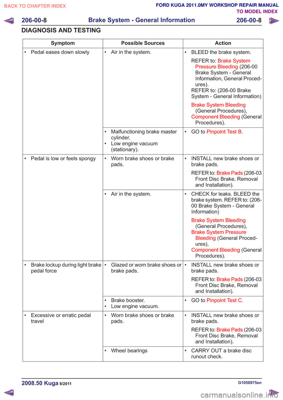
Action
Possible Sources
Symptom
• BLEED the brake system.REFER to: Brake System
Pressure Bleeding (206-00
Brake System - General
Information, General Proced-
ures).
REFER to: (206-00 Brake
System - General Information)
Brake System Bleeding (General Procedures),
Component Bleeding (General
Procedures).
• Air in the system.
• Pedal eases down slowly
• GO toPinpoint Test B.
• Malfunctioning brake master
cylinder.
• Low engine vacuum (stationary).
• INSTALL new brake shoes orbrake pads.
REFER to: Brake Pads (206-03
Front Disc Brake, Removal
and Installation).
• Worn brake shoes or brake
pads.
• Pedal is low or feels spongy
• CHECK for leaks. BLEED thebrake system. REFER to: (206-
00 Brake System - General
Information)
Brake System Bleeding (General Procedures),
Brake System Pressure Bleeding (General Proced-
ures),
Component Bleeding (General
Procedures).
• Air in the system.
• INSTALL new brake shoes orbrake pads.
REFER to: Brake Pads (206-03
Front Disc Brake, Removal
and Installation).
• Glazed or worn brake shoes or
brake pads.
• Brake lockup during light brake
pedal force
• GO toPinpoint Test C.
• Brake booster.
• Low engine vacuum.
• INSTALL new brake shoes orbrake pads.
REFER to: Brake Pads (206-03
Front Disc Brake, Removal
and Installation).
• Worn brake shoes or brake
pads.
• Excessive or erratic pedal
travel
• CARRY OUT a brake discrunout check.
• Wheel bearings
G1058975en2008.50 Kuga8/2011
206-00-
8
Brake System - General Information
206-00- 8
DIAGNOSIS AND TESTING
TO MODEL INDEX
BACK TO CHAPTER INDEX
FORD KUGA 2011.0MY WORKSHOP REPAIR MANUAL
Page 1348 of 2057

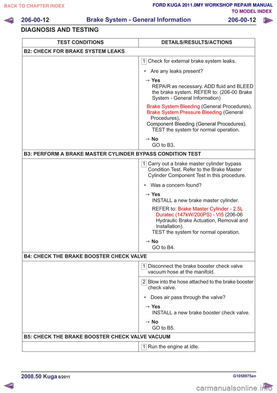
DETAILS/RESULTS/ACTIONS
TEST CONDITIONS
B2: CHECK FOR BRAKE SYSTEM LEAKS
1 Check for external brake system leaks.
• Are any leaks present?
zYe s REPAIR as necessary. ADD fluid and BLEED
the brake system. REFER to: (206-00 Brake
System - General Information)
Brake System Bleeding (General Procedures),
Brake System Pressure Bleeding (General
Procedures),
Component Bleeding (General Procedures).
TEST the system for normal operation.
zNo
GO to B3.
B3: PERFORM A BRAKE MASTER CYLINDER BYPASS CONDITION TEST
1 Carry out a brake master cylinder bypass
Condition Test. Refer to the Brake Master
Cylinder Component Test in this procedure.
• Was a concern found?
zYe s INSTALL a new brake master cylinder.
REFER to: Brake Master Cylinder - 2.5L
Duratec (147kW/200PS) - VI5 (206-06
Hydraulic Brake Actuation, Removal and
Installation).
TEST the system for normal operation.
zNo
GO to B4.
B4: CHECK THE BRAKE BOOSTER CHECK VALVE
1 Disconnect the brake booster check valve
vacuum hose at the manifold.
2Blow into the hose attached to the brake booster
check valve.
• Does air pass through the valve?
zYe s INSTALL a new brake booster check valve.
zNoGO to B5.
B5: CHECK THE BRAKE BOOSTER CHECK VALVE VACUUM
1 Run the engine at idle.
G1058975en2008.50 Kuga8/2011
206-00-
12
Brake System - General Information
206-00- 12
DIAGNOSIS AND TESTING
TO MODEL INDEX
BACK TO CHAPTER INDEX
FORD KUGA 2011.0MY WORKSHOP REPAIR MANUAL