2011 FORD KUGA fuel type
[x] Cancel search: fuel typePage 63 of 2057

Road/Roller Testing
Road or roller testing may be carried out for various
reasons and a procedure detailing pre-test checks,
engine starting and stopping, pre-driving checks,
on-test checks and final checks to be completed
on completion of the test is given below.
Unless complete vehicle performance is being
checked, the full road test procedure need not be
carried out. Instead, those items particularly
relevant to the system(s) being checked can be
extracted.
Pre-Test Checks
WARNING: If the brake system hydraulic
fluid level is low, pedal travel is excessive
or a hydraulic leak is found, do not attempt
to road test the vehicle until the reason for
the low fluid level, excessive pedal travel
or hydraulic leak is found and rectified.
It is suggested that pre-test checks and functional
tests of those systems and circuits which affect the
safe and legal operations of the vehicle, such as
brakes, lights and steering, should always be
carried out before the road or roller test.
With the ignition switched off, check:
– the engine oil level.
– the engine coolant level.
– the tires, for correct pressure, compatible types and tread patterns, and wear within limits.
– that there is sufficient fuel in the tank to complete the test.
– all around the engine, transmission and under the vehicle for oil, coolant, hydraulic and fuel
leaks. Make a note of any apparent leaks and
wipe off the surrounding areas to make it easier
to identify the extent of the leak on completion
of the test.
Starting the Engine
NOTE: On initial drive away from cold and within
the first 1.5 km (1 mile), do not depress the
accelerator pedal beyond half travel until the
vehicle has attained a minimum speed of 25 km/h
(15 miles/h). Never operate at high engine speed
or with the accelerator pedal at full travel whilst the
engine is cold.
With the ignition switched off, check: – that the parking brake is applied.
– that the gear lever is in the neutral position.
– that all instrument gauges (except fuel gauge)
read zero.
With the ignition switched on, check:
– that the ignition controlled warning lamps are illuminated.
– that the engine temperature gauge registers a reading compatible with the engine temperature.
– that the fuel gauge registers a reading appropriate to the fuel level in the tank.
– the operation of the parking brake warning lamp and fluid level warning indicator.
Road or Roller Testing
CAUTION: If road testing, check the brake
operation while still traveling at low speed
before continuing with the test. If the
brakes pull to one side, or appear to be
otherwise faulty, do not continue with the
road test until the fault has been found and
rectified.
During the road or roller test, check:
– that the clutch pedal operation is not stiff or heavy.
– that the initial gear engagement is smooth and there is no evidence of clutch drag.
– that the parking brake control operates smoothly and releases quickly and completely.
– that the clutch takes up the drive smoothly, without slip or judder.
– that gear changing is smooth with no abnormal noises or vibrations from the transmission.
– the engine power output is satisfactory, full power is achieved, acceleration is smooth and
pedal operation is not stiff or heavy, and engine
speed returns to idle correctly.
– there is no excessive or abnormally colored smoke from the engine under normal driving,
heavy load or overrun conditions.
– that steering operation, including power steering (if equipped), is smooth, accurate, not
excessively heavy or with excessive free play
or vibration.
– that the steering does not pull to one side and self centers smoothly after cornering.
G17375en2008.50 Kuga8/2011
100-00- 58
General Information
100-00- 58
DESCRIPTION AND OPERATION
TO MODEL INDEX
BACK TO CHAPTER INDEX
FORD KUGA 2011.0MY WORKSHOP REPAIR MANUAL
Page 191 of 2057
• Navigation
• Fuel cap release
• Engine type
• Display language
In addition the new instrument cluster will require
the original odometer value to be entered.
After the installation and configuration of a new
instrument cluster. The passive anti-theft system
(PATS) will require programming by selecting the
Security Access routine on the Ford approved
diagnostic tool.
G1054964en
2008.50 Kuga 8/2011 413-01-8
Instrument Cluster
413-01-8
DIAGNOSIS AND TESTINGTO MODEL INDEX
BACK TO CHAPTER INDEX
FORD KUGA 2011.0MY WORKSHOP REPAIR MANUAL
Page 1518 of 2057
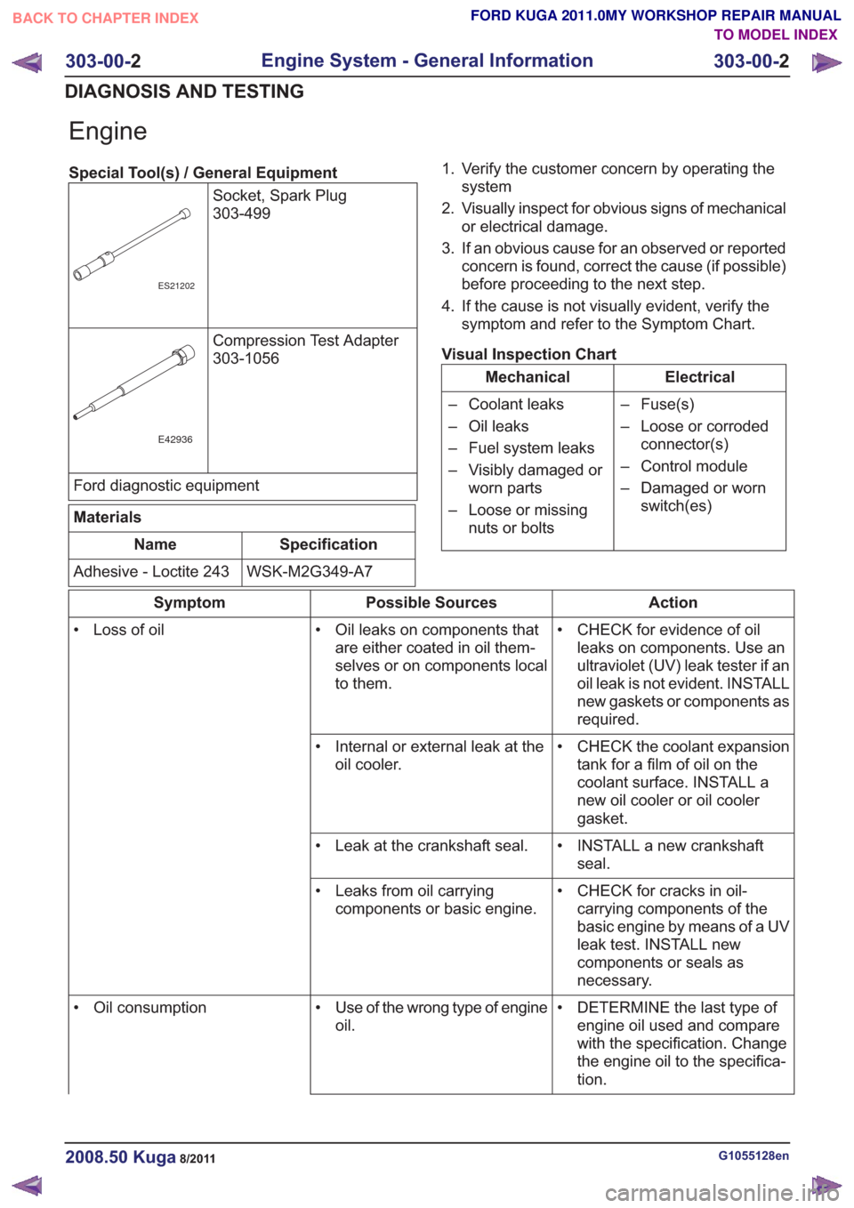
Engine
Special Tool(s) / General EquipmentSocket, Spark Plug
303-499
ES21202
Compression Test Adapter
303-1056
E42936
Ford diagnostic equipment
Materials
Specification
Name
WSK-M2G349-A7
Adhesive - Loctite 243 1. Verify the customer concern by operating the
system
2. Visually inspect for obvious signs of mechanical or electrical damage.
3. If an obvious cause for an observed or reported concern is found, correct the cause (if possible)
before proceeding to the next step.
4. If the cause is not visually evident, verify the symptom and refer to the Symptom Chart.
Visual Inspection Chart
Electrical
Mechanical
– Fuse(s)
– Loose or corrodedconnector(s)
– Control module
– Damaged or worn switch(es)
– Coolant leaks
– Oil leaks
– Fuel system leaks
– Visibly damaged or
worn parts
– Loose or missing nuts or bolts
Action
Possible Sources
Symptom
• CHECK for evidence of oilleaks on components. Use an
ultraviolet (UV) leak tester if an
oil leak is not evident. INSTALL
new gaskets or components as
required.
• Oil leaks on components that
are either coated in oil them-
selves or on components local
to them.
• Loss of oil
• CHECK the coolant expansiontank for a film of oil on the
coolant surface. INSTALL a
new oil cooler or oil cooler
gasket.
• Internal or external leak at the
oil cooler.
• INSTALL a new crankshaftseal.
• Leak at the crankshaft seal.
• CHECK for cracks in oil-carrying components of the
basic engine by means of a UV
leak test. INSTALL new
components or seals as
necessary.
• Leaks from oil carrying
components or basic engine.
• DETERMINE the last type ofengine oil used and compare
with the specification. Change
the engine oil to the specifica-
tion.
• Use of the wrong type of engine
oil.
• Oil consumption
G1055128en2008.50 Kuga8/2011
303-00-
2
Engine System - General Information
303-00- 2
DIAGNOSIS AND TESTING
TO MODEL INDEX
BACK TO CHAPTER INDEX
FORD KUGA 2011.0MY WORKSHOP REPAIR MANUAL
Page 1524 of 2057
Action
Possible Sources
Symptom
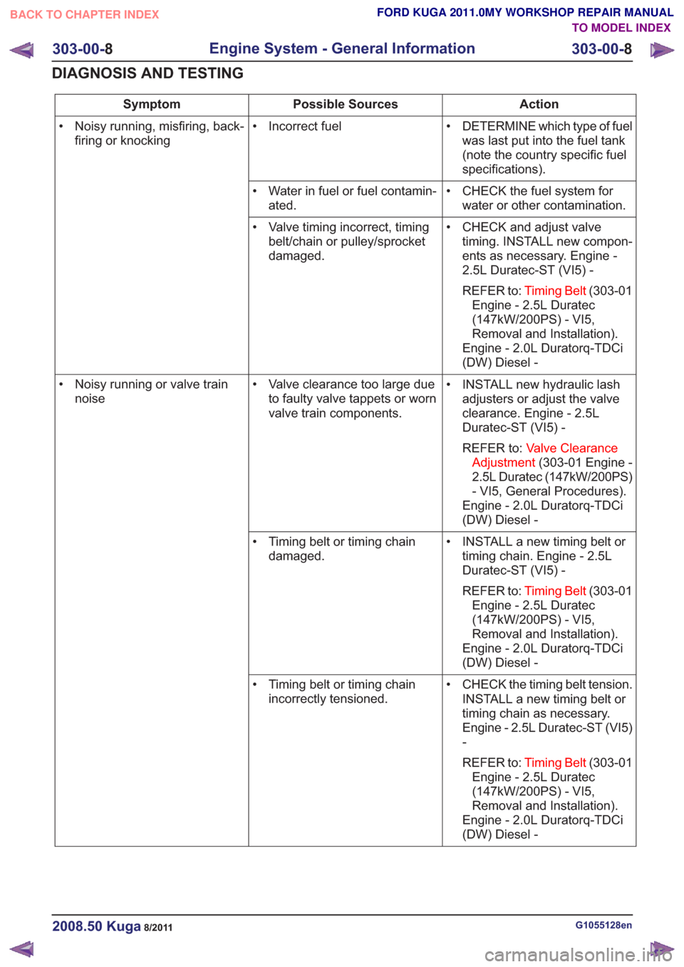
• DETERMINE which type of fuelwas last put into the fuel tank
(note the country specific fuel
specifications).
• Incorrect fuel
• Noisy running, misfiring, back-
firing or knocking
• CHECK the fuel system forwater or other contamination.
• Water in fuel or fuel contamin-
ated.
• CHECK and adjust valvetiming. INSTALL new compon-
ents as necessary. Engine -
2.5L Duratec-ST (VI5) -
REFER to: Timing Belt (303-01
Engine - 2.5L Duratec
(147kW/200PS) - VI5,
Removal and Installation).
Engine - 2.0L Duratorq-TDCi
(DW) Diesel -
• Valve timing incorrect, timing
belt/chain or pulley/sprocket
damaged.
• INSTALL new hydraulic lashadjusters or adjust the valve
clearance. Engine - 2.5L
Duratec-ST (VI5) -
REFER to: Valve Clearance
Adjustment (303-01 Engine -
2.5L Duratec (147kW/200PS)
- VI5, General Procedures).
Engine - 2.0L Duratorq-TDCi
(DW) Diesel -
• Valve clearance too large due
to faulty valve tappets or worn
valve train components.
• Noisy running or valve train
noise
• INSTALL a new timing belt ortiming chain. Engine - 2.5L
Duratec-ST (VI5) -
REFER to: Timing Belt (303-01
Engine - 2.5L Duratec
(147kW/200PS) - VI5,
Removal and Installation).
Engine - 2.0L Duratorq-TDCi
(DW) Diesel -
• Timing belt or timing chain
damaged.
• CHECK the timing belt tension.INSTALL a new timing belt or
timing chain as necessary.
Engine - 2.5L Duratec-ST (VI5)
-
REFER to: Timing Belt (303-01
Engine - 2.5L Duratec
(147kW/200PS) - VI5,
Removal and Installation).
Engine - 2.0L Duratorq-TDCi
(DW) Diesel -
• Timing belt or timing chain
incorrectly tensioned.
G1055128en2008.50 Kuga8/2011
303-00- 8
Engine System - General Information
303-00- 8
DIAGNOSIS AND TESTING
TO MODEL INDEX
BACK TO CHAPTER INDEX
FORD KUGA 2011.0MY WORKSHOP REPAIR MANUAL
Page 1527 of 2057
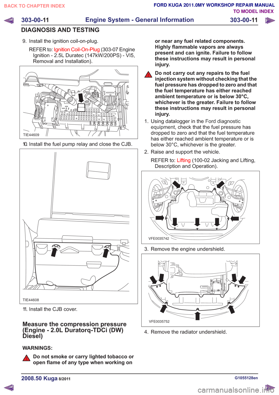
9. Install the ignition coil-on-plug.REFER to: Ignition Coil-On-Plug (303-07 Engine
Ignition - 2.5L Duratec (147kW/200PS) - VI5,
Removal and Installation).
TIE44609
10. Install the fuel pump relay and close the CJB.
TIE44608
11. Install the CJB cover.
Measure the compression pressure
(Engine - 2.0L Duratorq-TDCi (DW)
Diesel)
WARNINGS:
Do not smoke or carry lighted tobacco or
open flame of any type when working on or near any fuel related components.
Highly flammable vapors are always
present and can ignite. Failure to follow
these instructions may result in personal
injury.
Do not carry out any repairs to the fuel
injection system without checking that the
fuel pressure has dropped to zero and that
the fuel temperature has either reached
ambient temperature or is below 30°C,
whichever is the greater. Failure to follow
these instructions may result in personal
injury.
1. Using datalogger in the Ford diagnostic
equipment , check that the fuel pressure has
dropped to zero and that the fuel temperature
has either reached ambient temperature or is
below 30°C, whichever is the greater.
2. Raise and support the vehicle.
REFER to: Lifting(100-02 Jacking and Lifting,
Description and Operation).
VFE0035742
3. Remove the engine undershield.
VFE0035752
4. Remove the radiator undershield.
G1055128en2008.50 Kuga8/2011
303-00- 11
Engine System - General Information
303-00- 11
DIAGNOSIS AND TESTING
TO MODEL INDEX
BACK TO CHAPTER INDEX
FORD KUGA 2011.0MY WORKSHOP REPAIR MANUAL
Page 1847 of 2057

E112322
The TCM adapts the gear changing to ensure that
the correct gear is selected for the style of driving,
the engine load, driver requirements, vehicle speed
etc. This leads to lower fuel consumption together
with improved comfort through smoother gear
changes and lower noise levels.
The TCM receives information on the driver's
desired transmission range and type of driving
mode. In contrast to a transmission which is only
controlled hydraulically, the control module can
calculate the best times to shift gear and activate
torque converter lockup by using the signals from
the sensors in the transmission and the engine
management system.
The control module enables small changes in the
operating conditions to be made and adapts thevarious transmission functions to ensure that the
correct gear is always selected in relation to the
type of driving mode.
The TCM has adaptive capabilities. This ensures
smooth gear changes throughout the whole service
life of the transmission.
To exactly determine the activation points of the
gear shifts and torque converter lockup on the
basis of the type of driving mode chosen, the TCM
receives the following information:
• Transmission range chosen (TR sensor).
• Type of driving mode chosen
(normal/sport/select-shift).
• Transmission input shaft speed (TSS sensor).
• Transmission output shaft speed (OSS sensor).
• Transmission fluid temperature (TFT sensor).
• The engine speed and the torque as well as the throttle plate opening - from the PCM via the
CAN data bus.
• Actuation of the accelerator pedal - from the PCM via the CAN data bus.
• Coolant temperature - from the PCM via the CAN data bus.
• Vehicle speed - from the ABS via the CAN data bus.
• Actuation of the brake pedal - from the ABS via the CAN data bus.
Pin assignment for TCM connector 'A' (connection to vehicle)
11
E125669
Description
Item
Battery (+)
1
not assigned
2Description
Item
not assigned
3
not assigned
4
G1163605en2008.50 Kuga8/2011
307-01- 26
Automatic Transmission/Transaxle
— Vehicles With:
5-Speed Automatic Transaxle - AW55 AWD
307-01- 26
DESCRIPTION AND OPERATION
TO MODEL INDEX
BACK TO CHAPTER INDEX
FORD KUGA 2011.0MY WORKSHOP REPAIR MANUAL
Page 1849 of 2057
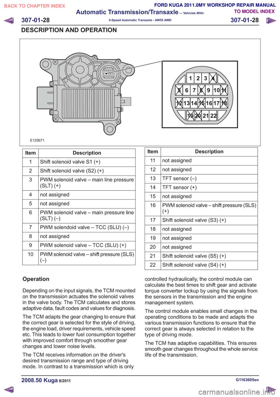
21
22 20 19
15 14 13
161718 12
876
9
10
11 5
3
42121
22 20 19
15 14 13
161718 12
876
9
10
11 5
3
421
E125671
Description
Item
Shift solenoid valve S1 (+)
1
Shift solenoid valve (S2) (+)
2
PWM solenoid valve – main line pressure
(SLT) (+)
3
not assigned
4
not assigned
5
PWM solenoid valve – main pressure line
(SLT) (–)
6
PWM solendoid valve – TCC (SLU) (–)
7
not assigned
8
PWM solenoid valve – TCC (SLU) (+)
9
PWM solenoid valve – shift pressure (SLS)
(–)
10Description
Item
not assigned
11
not assigned
12
TFT sensor (–)
13
TFT sensor (+)
14
not assigned
15
PWM solenoid valve – shift pressure (SLS)
(+)
16
Shift solenoid valve (S3) (+)
17
not assigned
18
not assigned
19
not assigned
20
Shift solenoid valve (S5) (+)
21
Shift solenoid valve (S4) (+)
22
Operation
Depending on the input signals, the TCM mounted
on the transmission actuates the solenoid valves
in the valve body. The TCM calculates and stores
adaptive data, fault codes and values for diagnosis.
The TCM adapts the gear changing to ensure that
the correct gear is selected for the style of driving,
the engine load, driver requirements, vehicle speed
etc. This leads to lower fuel consumption together
with improved comfort through smoother gear
changes and lower noise levels.
The TCM receives information on the driver's
desired transmission range and type of driving
mode. In contrast to a transmission which is only controlled hydraulically, the control module can
calculate the best times to shift gear and activate
torque converter lockup by using the signals from
the sensors in the transmission and the engine
management system.
The control module enables small changes in the
operating conditions to be made and adapts the
various transmission functions to ensure that the
correct gear is always selected in relation to the
type of driving mode.
The TCM has adaptive capabilities. This ensures
smooth gear changes throughout the whole service
life of the transmission.
G1163605en2008.50 Kuga8/2011
307-01-
28
Automatic Transmission/Transaxle
— Vehicles With:
5-Speed Automatic Transaxle - AW55 AWD
307-01- 28
DESCRIPTION AND OPERATION
TO MODEL INDEX
BACK TO CHAPTER INDEX
FORD KUGA 2011.0MY WORKSHOP REPAIR MANUAL
Page 1876 of 2057
Description
Item
Drive
3
Intake side
4
Delivery side
5
The fluid pump operates on the principle of a
G-rotor fluid pump.
The fluid pump draws transmission fluid from the
fluid pan, builds up fluid pressure and then supplies
it to the valve body.
The fluid pump is driven by the crankshaft via the
torque converter housing.
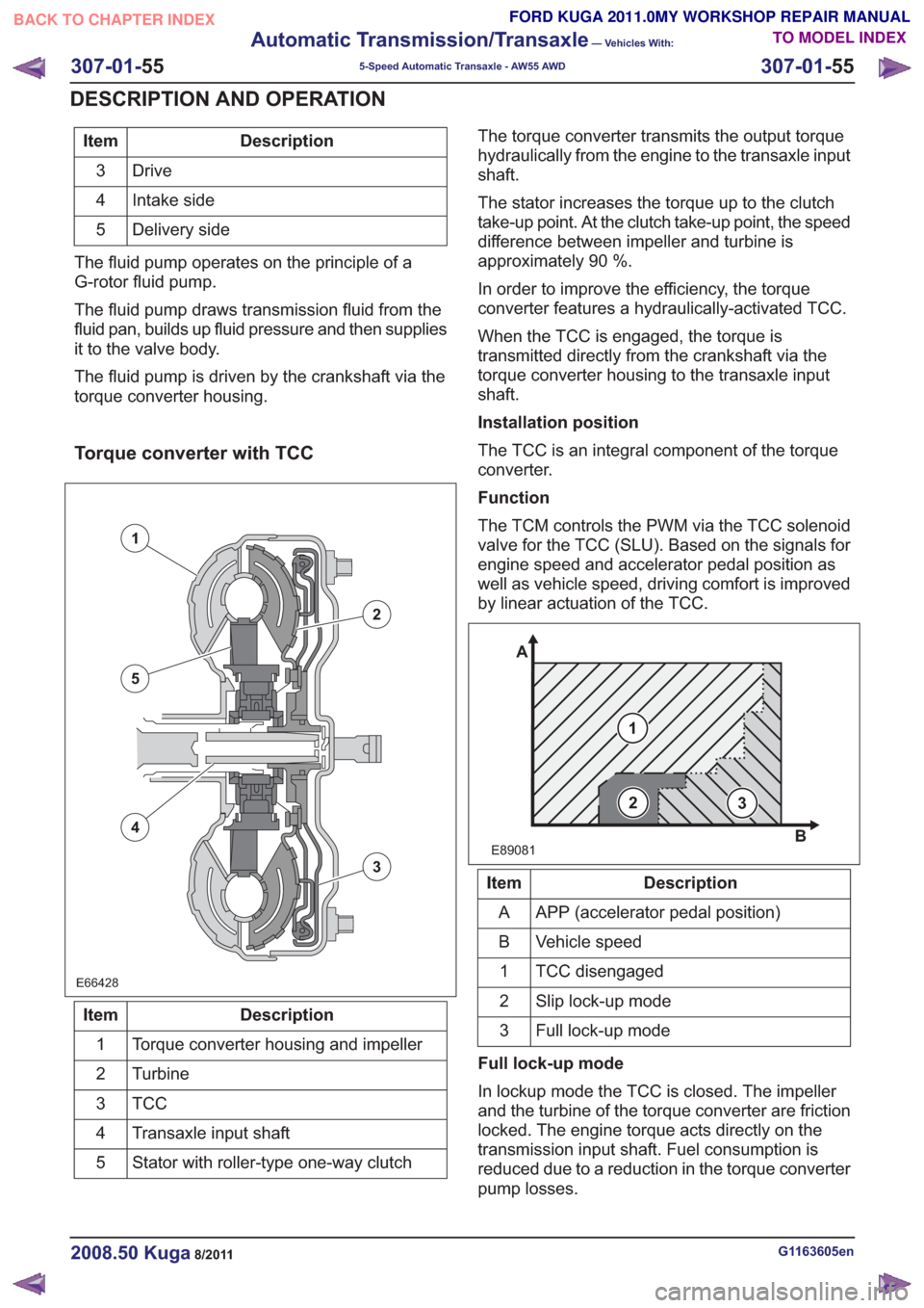
Torque converter with TCC
E66428E66428
1
2
3
5
4
Description
Item
Torque converter housing and impeller
1
Turbine
2
TCC3
Transaxle input shaft
4
Stator with roller-type one-way clutch
5 The torque converter transmits the output torque
hydraulically from the engine to the transaxle input
shaft.
The stator increases the torque up to the clutch
take-up point. At the clutch take-up point, the speed
difference between impeller and turbine is
approximately 90 %.
In order to improve the efficiency, the torque
converter features a hydraulically-activated TCC.
When the TCC is engaged, the torque is
transmitted directly from the crankshaft via the
torque converter housing to the transaxle input
shaft.
Installation position
The TCC is an integral component of the torque
converter.
Function
The TCM controls the PWM via the TCC solenoid
valve for the TCC (SLU). Based on the signals for
engine speed and accelerator pedal position as
well as vehicle speed, driving comfort is improved
by linear actuation of the TCC.
E89081
1
A
B
23
Description
Item
APP (accelerator pedal position)
A
Vehicle speed
B
TCC disengaged
1
Slip lock-up mode
2
Full lock-up mode
3
Full lock-up mode
In lockup mode the TCC is closed. The impeller
and the turbine of the torque converter are friction
locked. The engine torque acts directly on the
transmission input shaft. Fuel consumption is
reduced due to a reduction in the torque converter
pump losses.
G1163605en2008.50 Kuga8/2011
307-01- 55
Automatic Transmission/Transaxle
— Vehicles With:
5-Speed Automatic Transaxle - AW55 AWD
307-01- 55
DESCRIPTION AND OPERATION
TO MODEL INDEX
BACK TO CHAPTER INDEX
FORD KUGA 2011.0MY WORKSHOP REPAIR MANUAL