Page 377 of 573

POWER STEERING
The standard power steering system will give you good
vehicle response and increased ease of maneuverability
in tight spaces. The system will provide mechanical
steering capability if power assist is lost.
If for some reason the power assist is interrupted, it will
still be possible to steer your vehicle. Under these condi-
tions, you will observe a substantial increase in steering
effort, especially at very low vehicle speeds and during
parking maneuvers.
NOTE:
•Increased noise levels at the end of the steering wheel
travel are considered normal and do not indicate that
there is a problem with the power steering system.
•Upon initial start-up in cold weather, the power steer-
ing pump may make noise for a short amount of time.
This is due to the cold, thick fluid in the steering
system. This noise should be considered normal, and it
does not in any way damage the steering system.
WARNING!
Continued operation with reduced power steering
assist could pose a safety risk to yourself and others.
Service should be obtained as soon as possible.
CAUTION!
Prolonged operation of the steering system at the end
of the steering wheel travel will increase the steering
fluid temperature and it should be avoided when
possible. Damage to the power steering pump may
occur.
374 STARTING AND OPERATING
Page 378 of 573

Power Steering Fluid Check
Checking the power steering fluid level at a defined
service interval is not required. The fluid should only be
checked if a leak is suspected, abnormal noises are
apparent, and/or the system is not functioning as antici-
pated. Coordinate inspection efforts through an autho-
rized dealer.
CAUTION!
Do not use chemical flushes in your power steering
system as the chemicals can damage your power
steering components. Such damage is not covered by
the New Vehicle Limited Warranty.
WARNING!
Fluid level should be checked on a level surface and
with the engine off to prevent injury from moving
parts and to ensure accurate fluid level reading. Do
not overfill. Use only manufacturer’s recommended
power steering fluid.
If necessary, add fluid to restore to the proper indicated
level. With a clean cloth, wipe any spilled fluid from all
surfaces. Refer to “Fluids, Lubricants, and Genuine
Parts” in “Maintaining Your Vehicle” for further
information.
PARKING BRAKE
Before leaving the vehicle, make sure that the parking
brake is fully applied and place the shift lever in the
PARK position.
5
STARTING AND OPERATING 375
Page 380 of 573

difficult to move the shift lever out of PARK. The parking
brake should always be applied whenever the driver is
not in the vehicle.
WARNING!
•Never leave children alone in a vehicle. Leaving
unattended children in a vehicle is dangerous for a
number of reasons. A child or others could be
seriously or fatally injured.
•Do not leave the key fob in the ignition switch. A
child could operate power windows, other con-
trols, or move the vehicle.
•Be sure the parking brake is fully disengaged
before driving; failure to do so can lead to brake
failure and a collision.(Continued)
WARNING! (Continued)
•Always fully apply the parking brake when leav-
ing your vehicle, or it may roll and cause damage
or injury. Also be certain to leave the transmission
in PARK. Failure to do so may allow the vehicle to
roll and cause damage or injury.
CAUTION!
If the Brake System Warning Light remains on with
the parking brake released, a brake system malfunc-
tion is indicated. Have the brake system serviced by
an authorized dealer immediately.
ANTI-LOCK BRAKE SYSTEM (ABS)
The Anti-Lock Brake System (ABS) provides increased
vehicle stability and brake performance under most
braking conditions. The system operates with a separate
5
STARTING AND OPERATING 377
Page 382 of 573

WARNING! (Continued)
•The Anti-Lock Brake System cannot prevent colli-
sions, including those resulting from excessive
speed in turns, following another vehicle too
closely, or hydroplaning.
•The capabilities of an ABS-equipped vehicle must
never be exploited in a reckless or dangerous
manner, which could jeopardize the user ’s safety
or the safety of others.
All vehicle wheels and tires must be the same size and
type, and tires must be properly inflated to produce
accurate signals for the computer.
Anti-Lock Brake Warning Light
The “Anti-Lock Brake Warning Light” moni-
tors the anti-lock brake system. The light will come on when the ignition switch is turned to the ON
position and may stay on for as long as four seconds.
If the “Anti-Lock Brake Warning Light” remains on or
comes on while driving, it indicates that the anti-lock
portion of the brake system is not functioning and that
service is required. However, the conventional brake
system will continue to operate normally if the “Brake
Warning Light” is not on.
If the “Anti-Lock Brake Warning Light” is on, the brake
system should be serviced as soon as possible to restore
the benefits of anti-lock brakes. If the “Anti-Lock Brake
Warning Light” does not come on when the ignition
switch is turned to the ON position, have the bulb
repaired as soon as possible.
If both the “Brake Warning Light” and the “Anti-Lock
Brake Warning Light” remain on, the ABS and Electronic
5
STARTING AND OPERATING 379
Page 383 of 573

Brake Force Distribution (EBD) systems are not function-
ing. Immediate repair to the ABS system is required.
Consult with your authorized dealer service center as
soon as possible.
ELECTRONIC BRAKE CONTROL SYSTEM
Your vehicle is equipped with an advanced electronic
brake control system that includes the Traction Control
System (TCS), Brake Assist System (BAS) and Electronic
Stability Control (ESC). These systems complement the
Anti-Lock Brake System (ABS) by optimizing the vehicle
braking capability during emergency braking maneu-
vers.
Traction Control System (TCS)
The Traction Control System (TCS) monitors the amount
of wheel spin of each of the driven wheels. If wheel spin
is detected, brake pressure is applied to the slipping
wheel(s) and engine power is reduced, to provide en-
hanced acceleration and stability. A feature of the TCSfunctions similarly to a limited-slip differential, and
controls the wheel spin across a driven axle. If one wheel
on a driven axle is spinning faster than the other, the
system will apply the brake of the spinning wheel. This
will allow more engine torque to be applied to the wheel
that is not spinning. This feature remains active even if
the ESC is in the “Partial Off” mode.
The “ESC Activation/Malfunction Indicator Light” (in
the instrument cluster) will start to flash as soon as the
tires lose traction and the wheels begin to spin. This
indicates that the TCS is active. If the indicator light
flashes during acceleration, ease up on the accelerator
and apply as little throttle as possible. Be sure to adapt
your speed and driving to the prevailing road conditions,
and do not switch off the ESC or TCS.
380 STARTING AND OPERATING
Page 388 of 573
NOTE:
•The “ESC Activation/Malfunction Indicator Light”
and the “ESC OFF Indicator Light” come on momen-
tarily each time the ignition switch is turned ON.
•Each time the ignition is turned ON, the ESC system
will be ON even if it was turned off previously.
•The ESC system will make buzzing or clicking sounds
when it is active. This is normal; the sounds will stop
when ESC becomes inactive following the maneuver
that caused the ESC activation.The “ESC OFF Indicator Light” indicates the
Electronic Stability Control (ESC) is off.
TIRE SAFETY INFORMATION
Tire Markings
1 — U.S. DOT Safety
Standards Code (TIN) 4 — Maximum Load
2 — Size Designation 5 — Maximum Pressure
3 — Service Description 6 — Treadwear, Traction and Temperature Grades
5
STARTING AND OPERATING 385
Page 391 of 573

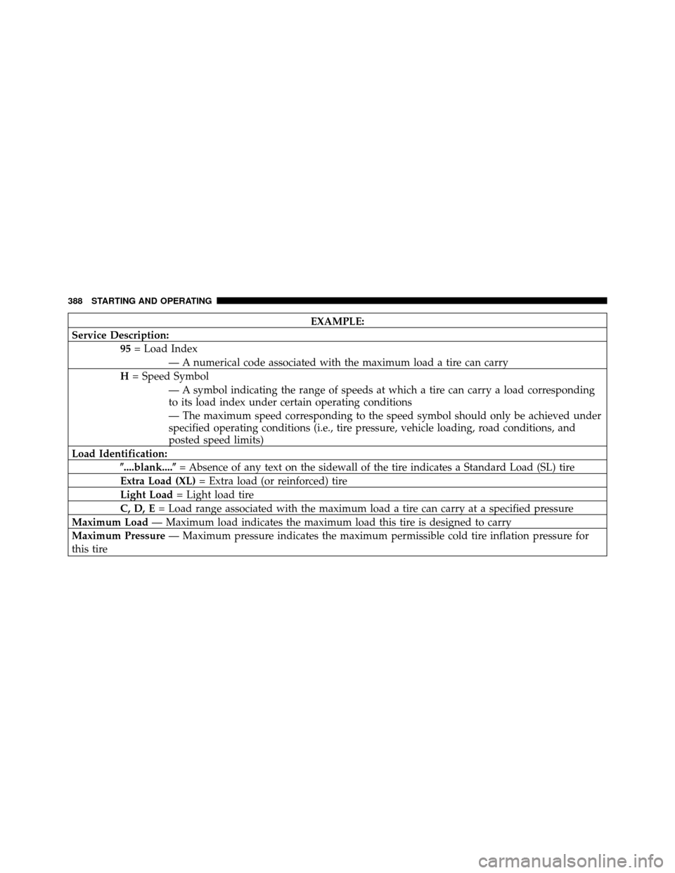
EXAMPLE:
Service Description: 95= Load Index
— A numerical code associated with the maximum load a tire can carry
H = Speed Symbol
— A symbol indicating the range of speeds at which a tire can carry a load corresponding
to its load index under certain operating conditions
— The maximum speed corresponding to the speed symbol should only be achieved under
specified operating conditions (i.e., tire pressure, vehicle loading, road conditions, and
posted speed limits)
Load Identification: �....blank....� = Absence of any text on the sidewall of the tire indicates a Standard Load (SL) tire
Extra Load (XL) = Extra load (or reinforced) tire
Light Load = Light load tire
C, D, E = Load range associated with the maximum load a tire can carry at a specified pressure
Maximum Load — Maximum load indicates the maximum load this tire is designed to carry
Maximum Pressure — Maximum pressure indicates the maximum permissible cold tire inflation pressure for
this tire
388 STARTING AND OPERATING
Page 405 of 573
Tread Wear Indicators
Tread wear indicators are in the original-equipment tires
to help you in determining when your tires should be
replaced.These indicators are molded into the bottom of the tread
grooves. They will appear as bands when the tread depth
becomes 1/16 in (2 mm). When the tread is worn to the
tread wear indicators, the tire should be replaced.
Life Of Tire
The service life of a tire is dependent upon varying
factors, including, but not limited to:
•Driving style
•Tire pressure
•Distance driven
WARNING!
The tires and the spare tire should be replaced after
six years, regardless of the remaining tread. Failure to
follow this warning can result in sudden tire failure.
You could lose control and have a collision resulting
in serious injury or death.
1 — Worn Tire
2 — New Tire
402 STARTING AND OPERATING