Page 92 of 573
Air Bag Warning Light
You will want to have the air bags ready to
inflate for your protection in a collision. The
Air Bag Warning Light monitors the internal
circuits and interconnecting wiring associated
with air bag system electrical components. While the air
bag system is designed to be maintenance free. If any of
the following occurs, have an authorized dealer service
the air bag system immediately.
•The Air Bag Warning Light does not come on during
the four to eight seconds when the ignition switch is
first turned to the ON/RUN position.
•The Air Bag Warning Light remains on after the four to
eight-second interval.
•The Air Bag Warning Light comes on intermittently or
remains on while driving. NOTE:
If the speedometer, tachometer, or any engine
related gauges are not working, the Occupant Restraint
Controller (ORC) may also be disabled. The air bags may
not be ready to inflate for your protection. Promptly
check the fuse block for blown fuses. Refer to the label
located on the inside of the fuse block cover for the
proper air bag fuses. See your authorized dealer if the
fuse is good.
Event Data Recorder (EDR)
This vehicle is equipped with an event data recorder
(EDR). The main purpose of an EDR is to record, in
certain crash or near crash-like situations, such as an air
bag deployment or hitting a road obstacle, data that will
assist in understanding how a vehicle’s systems per-
formed. The EDR is designed to record data related to
vehicle dynamics and safety systems for a short period of
time, typically 30 seconds or less. The EDR in this vehicle
is designed to record such data as:
•How various systems in your vehicle were operating;
2
THINGS TO KNOW BEFORE STARTING YOUR VEHICLE 89
Page 218 of 573
The outlet in the rear quarter panel near the liftgate and
the upper outlet in the instrument panel are both con-
trolled by the ignition switch. Each of these outlets can
support 160 Watts (13 Amps). Do not exceed 160 Watts
(13 Amps) for each of these outlets.
The power outlets include tethered caps, labeled with a
key or battery symbol indicating the power source. The
power outlet, located on the lower instrument panel, is
powered directly from the battery. Items plugged into
this power outlet may discharge the battery and/or
prevent the engine from starting.
Power Outlet Fuses
1 — M7 Fuse 20 A Yellow Power Outlet Center Seat (Opt) or
with Console Rear
2 — M6 Fuse 20 A Yellow Cigar Lighter Instrument Panel or
with Console Front
3 — M36 Fuse 20 A Yellow Power Outlet Instrument Panel or
with Console Center
3
UNDERSTANDING THE FEATURES OF YOUR VEHICLE 215
Page 259 of 573
LoW tirE
When the appropriate condition exists, the odometer
display will toggle between LoW and tirE for three cycles.
gASCAP
If the vehicle diagnostic system determines that the fuel
filler cap is loose, improperly installed, or damaged, a
“gASCAP” message will display in the odometer display
area. Tighten the fuel filler cap properly and press the
TRIP ODOMETER button to turn off the message. If the
problem continues, the message will appear the next time
the vehicle is started.
noFUSE
If the vehicle diagnostic system determines that the
Ignition Off Draw (IOD) fuse is improperly installed, or
damaged, a “noFUSE” message will display in the odom-
eter display area. For further information on fuses and
fuse locations refer to “Fuses” in “Maintaining Your
Vehicle”.CHAngE OIL
Your vehicle is equipped with an engine oil change
indicator system. The
CHAngE OILmessage will flash in
the instrument cluster odometer for approximately
12 seconds, after a single chime has sounded, to indicate
the next scheduled oil change interval. The engine oil
change indicator system is duty cycle-based, which
means the engine oil change interval may fluctuate
dependent upon your personal driving style.
Unless reset, this message will continue to display each
time you turn the ignition switch to the ON/RUN
position. To turn off the message temporarily, press and
release the Trip / Odometer Display reset button on the
instrument cluster. To reset the oil change indicator
system (after performing the scheduled maintenance),
perform the following steps.
1. Turn the ignition switch to the ON/RUN position (do
not start the engine).
256 UNDERSTANDING YOUR INSTRUMENT PANEL
Page 477 of 573
▫Automatic Transmission ............... 499
▫ Appearance Care And Protection From
Corrosion .......................... 501
▫ Cleaning The Instrument Panel Cupholders . . 506
� Fuses .............................. 507
▫ Totally Integrated Power Module ......... 507
� Vehicle Storage ....................... 514
� Replacement Bulbs .................... 514
� Bulb Replacement ..................... 515
▫ High Intensity Discharge Headlamps
(HID) — If Equipped ................. 515
▫ Quad Headlamps .................... 516 ▫
Front Park/Turn Signal Lamp ........... 516
▫ Front Side Marker Lamp ............... 516
▫ Fog Lamp ......................... 517
▫ Rear Tail, Stop, Turn Signal, Side Marker
And Backup Lamp ................... 517
▫ Center High-Mounted Stop Lamp
(CHMSL) .......................... 518
▫ License Lamp ....................... 519
� Fluid Capacities ...................... 519
� Fluids, Lubricants And Genuine Parts ....... 520
▫ Engine ............................ 520
▫ Chassis ........................... 521
474 MAINTAINING YOUR VEHICLE
Page 478 of 573
ENGINE COMPARTMENT — 3.6L
1 — Air Filter6 — Engine Coolant Reservoir
2 — Power Steering Fluid Reservoir 7 — Engine Oil Dipstick
3 — Brake Fluid Reservoir 8 — Engine Oil Fill
4 — Battery 9 — Coolant Pressure Cap
5 — Totally Integrated Power Module (Fuses) 10 — Washer Fluid Reservoir
7
MAINTAINING YOUR VEHICLE 475
Page 510 of 573
Installation
Place the liner into the cupholder drawer and press the
liner into place so that the retention tabs seat into the
corresponding openings in the drawer.
FUSES
Totally Integrated Power Module
The Totally Integrated Power Module is located in the
engine compartment near the battery. Refer to the appli-
cable “Engine Compartment” illustration in this section.
This center contains cartridge fuses and mini-fuses. A
label that identifies each component may be printed or
embossed on the inside of the cover.
Totally Integrated Power Module
7
MAINTAINING YOUR VEHICLE 507
Page 516 of 573
CavityCartridge
Fuse Mini-
Fuse Description
M34 — 10 Amp RedPark Assist, Heater
Climate Control Sys-
tem Module, Head-
lamp Wash, Compass,
IR Sensor, Rear Cam-
era, Lamp Door FT
Drv/Pass, Lamp
Flashlight, AHLM,
Relay Diesel Cabin
Heater, Rad Fan Die-
sel
M35 — 10 Amp RedHeated Mirrors
M36 — 20 Amp YellowPower Outlet #3Cavity
Cartridge
Fuse Mini-
Fuse Description
M37 — 10 Amp RedAntilock Brakes, Sta-
bility Control System,
Stop Lamp Switch,
Fuel Pump Rly Hi
Control
M38 — 25 Amp NaturalDoor Lock/Unlock
Motors, Liftgate
Lock/Unlock Motors
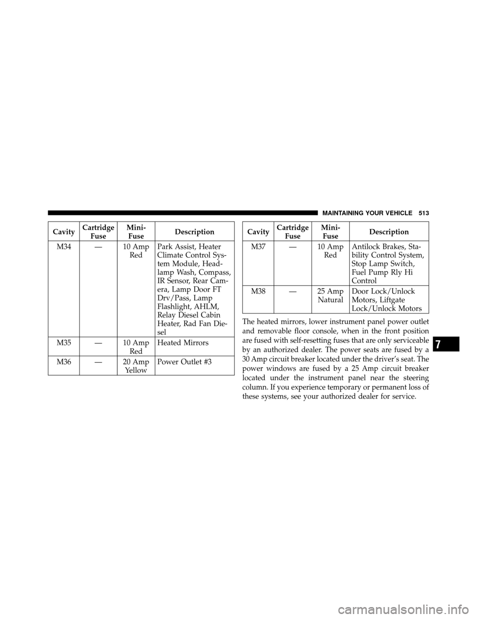
The heated mirrors, lower instrument panel power outlet
and removable floor console, when in the front position
are fused with self-resetting fuses that are only serviceable
by an authorized dealer. The power seats are fused by a
30 Amp circuit breaker located under the driver’s seat. The
power windows are fused by a 25 Amp circuit breaker
located under the instrument panel near the steering
column. If you experience temporary or permanent loss of
these systems, see your authorized dealer for service.
7
MAINTAINING YOUR VEHICLE 513
Page 560 of 573
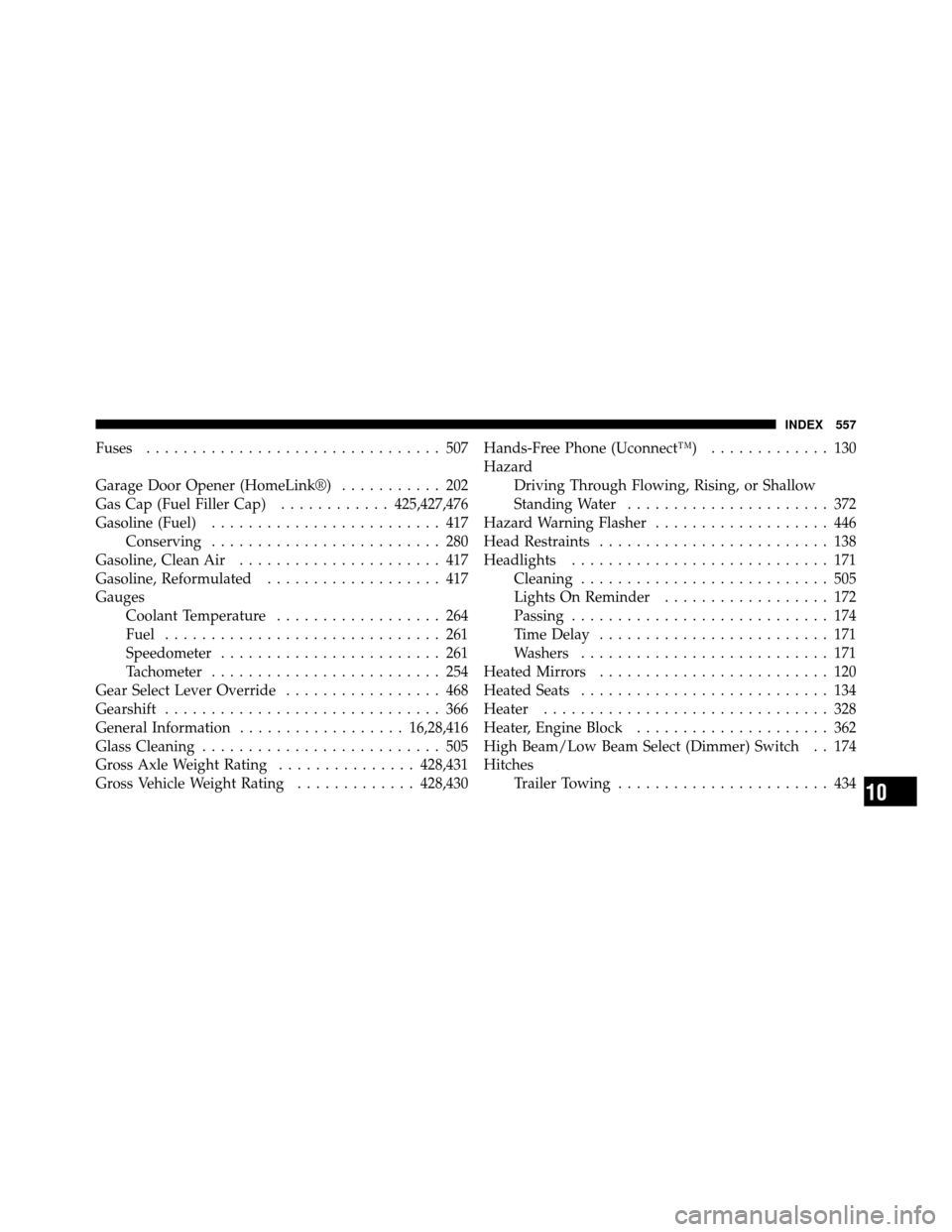
Fuses................................ 507
Garage Door Opener (HomeLink®) ........... 202
Gas Cap (Fuel Filler Cap) ............425,427,476
Gasoline (Fuel) ......................... 417
Conserving ......................... 280
Gasoline, Clean Air ...................... 417
Gasoline, Reformulated ................... 417
Gauges Coolant Temperature .................. 264
Fuel .............................. 261
Speedometer ........................ 261
Tachometer ......................... 254
Gear Select Lever Override ................. 468
Gearshift .............................. 366
General Information .................. 16,28,416
Glass Cleaning .......................... 505
Gross Axle Weight Rating ...............428,431
Gross Vehicle Weight Rating .............428,430Hands-Free Phone (Uconnect™)
............. 130
Hazard Driving Through Flowing, Rising, or Shallow
Standing Water ...................... 372
Hazard Warning Flasher ................... 446
Head Restraints ......................... 138
Headlights ............................ 171
Cleaning ........................... 505
Lights On Reminder .................. 172
Passing ............................ 174
Time Delay ......................... 171
Washers ........................... 171
Heated Mirrors ......................... 120
Heated Seats ........................... 134
Heater ............................... 328
Heater, Engine Block ..................... 362
High Beam/Low Beam Select (Dimmer) Switch . . 174
Hitches Trailer Towing ....................... 434
10
INDEX 557