Page 498 of 573
WARNING!
•The warning words “DO NOT OPEN HOT” on the
cooling system pressure cap are a safety precaution.
Never add engine coolant (antifreeze) when the
engine is overheated. Do not loosen or remove the
cap to cool an overheated engine. Heat causes
pressure to build up in the cooling system. To
prevent scalding or injury, do not remove the pres-
sure cap while the system is hot or under pressure.
•Do not use a pressure cap other than the one
specified for your vehicle. Personal injury or en-
gine damage may result.
Disposal Of Used Coolant
Used ethylene glycol-based engine coolant (antifreeze) is
a regulated substance requiring proper disposal. Check
with your local authorities to determine the disposalrules for your community. To prevent ingestion by ani-
mals or children, do not store ethylene glycol-based
engine coolant (antifreeze) in open containers or allow it
to remain in puddles on the ground. If ingested by a child
or pet, seek emergency assistance immediately. Clean up
any ground spills immediately.
Coolant Level
The coolant bottle provides a quick visual method for
determining that the coolant level is adequate. With the
engine cold, the level of the engine coolant (antifreeze) in
the coolant recovery bottle should be between the ranges
indicated on the bottle.
The radiator normally remains completely full, so there is
no need to remove the radiator cap unless checking for
engine coolant (antifreeze) freeze point or replacing the
engine coolant (antifreeze). Advise your service atten-
dant of this. As long as the engine operating temperature
is satisfactory, the coolant bottle only needs to be checked
once a month.
7
MAINTAINING YOUR VEHICLE 495
Page 500 of 573
•Do not change the thermostat for Summer or Winter
operation. If replacement is ever necessary, install
ONLY the correct type thermostat. Other designs may
result in unsatisfactory coolant performance, poor gas
mileage, and increased emissions.
Brakes
In order to assure brake system performance, all brake
system components should be inspected periodically.
Refer to the “Maintenance Schedule” for the proper
maintenance intervals.
WARNING!
Riding the brakes can lead to brake failure and
possibly a collision. Driving with your foot resting or
riding on the brake pedal can result in abnormally
high brake temperatures, excessive lining wear, and
possible brake damage. You would not have your full
braking capacity in an emergency.
Master Cylinder – Brake Fluid Level Check
The fluid level in the master cylinder should be checked
when performing underhood services, or immediately if
the “Brake System Warning Light” indicates system
failure.
Clean the top of the master cylinder area before removing
the cap. Add fluid to bring the level up to the top of the
“FULL” mark on the side of the master cylinder reservoir.
Overfilling of fluid is not recommended because it may
cause leaking in the system.
Add enough fluid to bring the level up to the require-
ments described on the brake fluid reservoir. With disc
brakes, fluid level can be expected to fall as the brake
pads wear. However, low fluid level may be caused by a
leak and a checkup may be needed.
7
MAINTAINING YOUR VEHICLE 497
Page 502 of 573
WARNING! (Continued)
•Do not allow petroleum based fluid to contami-
nate the brake fluid. Brake seal components could
be damaged, causing partial or complete brake
failure. This could result in a collision.
Automatic Transmission
The automatic transmission and differential assembly are
contained within a single housing.
The fluid level in the automatic transmission should be
checked whenever the vehicle is serviced. Operation with
an improper fluid level will greatly reduce the life of the
transmission and the fluid.
The six–speed transmission is equipped with a capped
dipstick tube. It is sealed and should not be tampered
with. Your authorized dealer has the necessary tools to
ensure that the fluid level is set properly.
Selection Of Lubricant
It is important that the proper lubricant is used in the
transmission to assure optimum transmission perfor-
mance. Use only the manufacturer’s recommended trans-
mission fluid. Refer to “Fluids, Lubricants, and Genuine
Parts” in “Maintaining Your Vehicle” for further informa-
tion. It is important that the transmission fluid be main-
tained at the prescribed level using the recommended
fluid. No chemical flushes should be used in any trans-
mission; only the approved lubricant may be used.
7
MAINTAINING YOUR VEHICLE 499
Page 503 of 573
CAUTION!
Using a transmission fluid other than the manufac-
turer’s recommended fluid may cause deterioration
in transmission shift quality and/or torque converter
shudder. Using a transmission fluid other than the
manufacturer’s recommended fluid will result in
more frequent fluid and filter changes. Refer to
“Fluids, Lubricants, and Genuine Parts” in “Main-
taining Your Vehicle” for further information.
Special Additives
Automatic Transmission Fluid (ATF) is an engineered
product and its performance may be impaired by supple-
mental additives. Therefore, do not add any fluid addi-
tives to the transmission. The only exception to this
policy is the use of special dyes to aid in detecting fluid
leaks. In addition, avoid using transmission sealers as
they may adversely affect seals.
CAUTION!
Do not use chemical flushes in your transmission as
the chemicals can damage your transmission compo-
nents. Such damage is not covered by the New
Vehicle Limited Warranty.
Fluid Level Check
The six-speed automatic transmission is a sealed unit and
has no dipstick. See your authorized dealer to have the
transmission fluid checked or serviced.
Fluid And Filter Changes
Refer to the “Maintenance Schedule” for the proper
maintenance intervals.
If the transmission is disassembled for any reason, the
fluid and filter should be changed.
500 MAINTAINING YOUR VEHICLE
Page 516 of 573
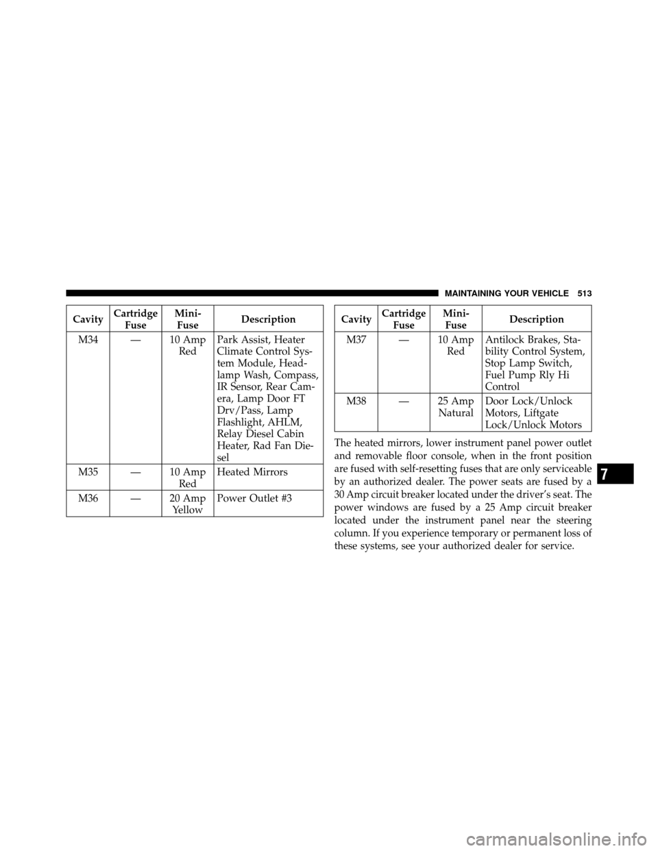
CavityCartridge
Fuse Mini-
Fuse Description
M34 — 10 Amp RedPark Assist, Heater
Climate Control Sys-
tem Module, Head-
lamp Wash, Compass,
IR Sensor, Rear Cam-
era, Lamp Door FT
Drv/Pass, Lamp
Flashlight, AHLM,
Relay Diesel Cabin
Heater, Rad Fan Die-
sel
M35 — 10 Amp RedHeated Mirrors
M36 — 20 Amp YellowPower Outlet #3Cavity
Cartridge
Fuse Mini-
Fuse Description
M37 — 10 Amp RedAntilock Brakes, Sta-
bility Control System,
Stop Lamp Switch,
Fuel Pump Rly Hi
Control
M38 — 25 Amp NaturalDoor Lock/Unlock
Motors, Liftgate
Lock/Unlock Motors
The heated mirrors, lower instrument panel power outlet
and removable floor console, when in the front position
are fused with self-resetting fuses that are only serviceable
by an authorized dealer. The power seats are fused by a
30 Amp circuit breaker located under the driver’s seat. The
power windows are fused by a 25 Amp circuit breaker
located under the instrument panel near the steering
column. If you experience temporary or permanent loss of
these systems, see your authorized dealer for service.
7
MAINTAINING YOUR VEHICLE 513
Page 517 of 573
VEHICLE STORAGE
If you are leaving your vehicle dormant for more than
21 days, you may want to take steps to protect your
battery. You may do the following:
•Remove the 20 Amp mini-fuse in the Totally Inte-
grated Power Module (TIPM) labeled Ignition-Off
Draw (IOD).
•Or, disconnect the negative cable from the battery.
•Anytime you store your vehicle, or keep it out of
service for two weeks or more, run the air conditioning
system at idle for about five minutes in the fresh air
and high blower setting. This will ensure adequate
system lubrication to minimize the possibility of com-
pressor damage when the system is started again.
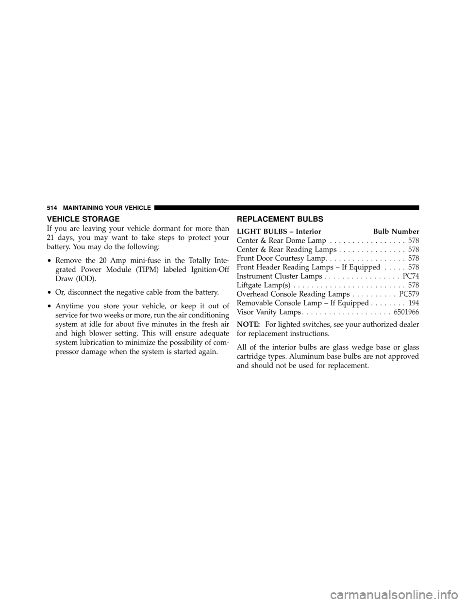
REPLACEMENT BULBS
LIGHT BULBS – InteriorBulb Number
Center & Rear Dome Lamp ................. 578
Center & Rear Reading Lamps ............... 578
Front Door Courtesy Lamp .................. 578
Front Header Reading Lamps – If Equipped ..... 578
Instrument Cluster Lamps .................PC74
Liftgate Lamp(s) ......................... 578
Overhead Console Reading Lamps ..........PC579
Removable Console Lamp – If Equipped ........ 194
Visor Vanity Lamps .................... 6501966
NOTE: For lighted switches, see your authorized dealer
for replacement instructions.
All of the interior bulbs are glass wedge base or glass
cartridge types. Aluminum base bulbs are not approved
and should not be used for replacement.
514 MAINTAINING YOUR VEHICLE
Page 518 of 573
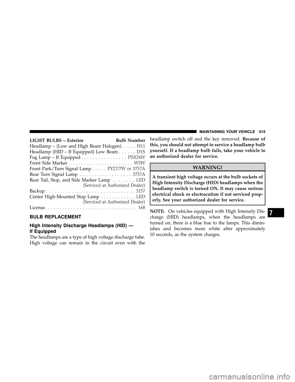
LIGHT BULBS – ExteriorBulb Number
Headlamp – (Low and High Beam Halogen) ..... H11
Headlamp (HID – If Equipped) Low Beam ...... D1S
Fog Lamp – If Equipped ................PSX24W
Front Side Marker ...................... W5W
Front Park/Turn Signal Lamp .....PY27/7W or 3757A
Rear Turn Signal Lamp .................. 3757A
Rear Tail, Stop, and Side Marker Lamp ........ LED
(Serviced at Authorized Dealer)
Backup ............................... 3157
Center High-Mounted Stop Lamp ............ LED
(Serviced at Authorized Dealer)
License ................................ 168
BULB REPLACEMENT
High Intensity Discharge Headlamps (HID) —
If Equipped
The headlamps are a type of high voltage discharge tube.
High voltage can remain in the circuit even with the headlamp switch off and the key removed.
Because of
this, you should not attempt to service a headlamp bulb
yourself. If a headlamp bulb fails, take your vehicle to
an authorized dealer for service.
WARNING!
A transient high voltage occurs at the bulb sockets of
High Intensity Discharge (HID) headlamps when the
headlamp switch is turned ON. It may cause serious
electrical shock or electrocution if not serviced prop-
erly. See your authorized dealer for service.
NOTE: On vehicles equipped with High Intensity Dis-
charge (HID) headlamps, when the headlamps are
turned on, there is a blue hue to the lamps. This dimin-
ishes and becomes more white after approximately
10 seconds, as the system charges.
7
MAINTAINING YOUR VEHICLE 515
Page 521 of 573
2. Remove the tail lamp assembly by removing the two
screws from the inboard side. Use a fiber stick or similar
tool to gently pry the light on the outboard side to
disengage the two ball studs.NOTE:
•If a screwdriver is used, make sure a soft material is
placed between the vehicle body and tool so not to
scratch the paint.
•The PRY location is best closest to the studs while
dislodging them separately.
3. Twist the socket and remove it from the lamp assem-
bly.
4. Pull the bulb to remove it from the socket.
5. Replace the bulb, reinstall the socket, and reattach the
lamp assembly.
Center High-Mounted Stop Lamp (CHMSL)
The CHMSL uses LED lamps that are not serviceable
separately. The CHMSL must be replaced as an assembly,
see your authorized dealer.
518 MAINTAINING YOUR VEHICLE