2010 VOLKSWAGEN TRANSPORTER key
[x] Cancel search: keyPage 94 of 486
A WARNING
The front passenger front airbag should only be switched off in exceptional circumstances.
• To prevent damage to the airbag system, only switch the front passenger front airbag on and off when the ignition is switched off.
• lt is the driver's responsibility to ensure that the key-operated switch is set to the cor-rect position.
Combined curtain and side airbags
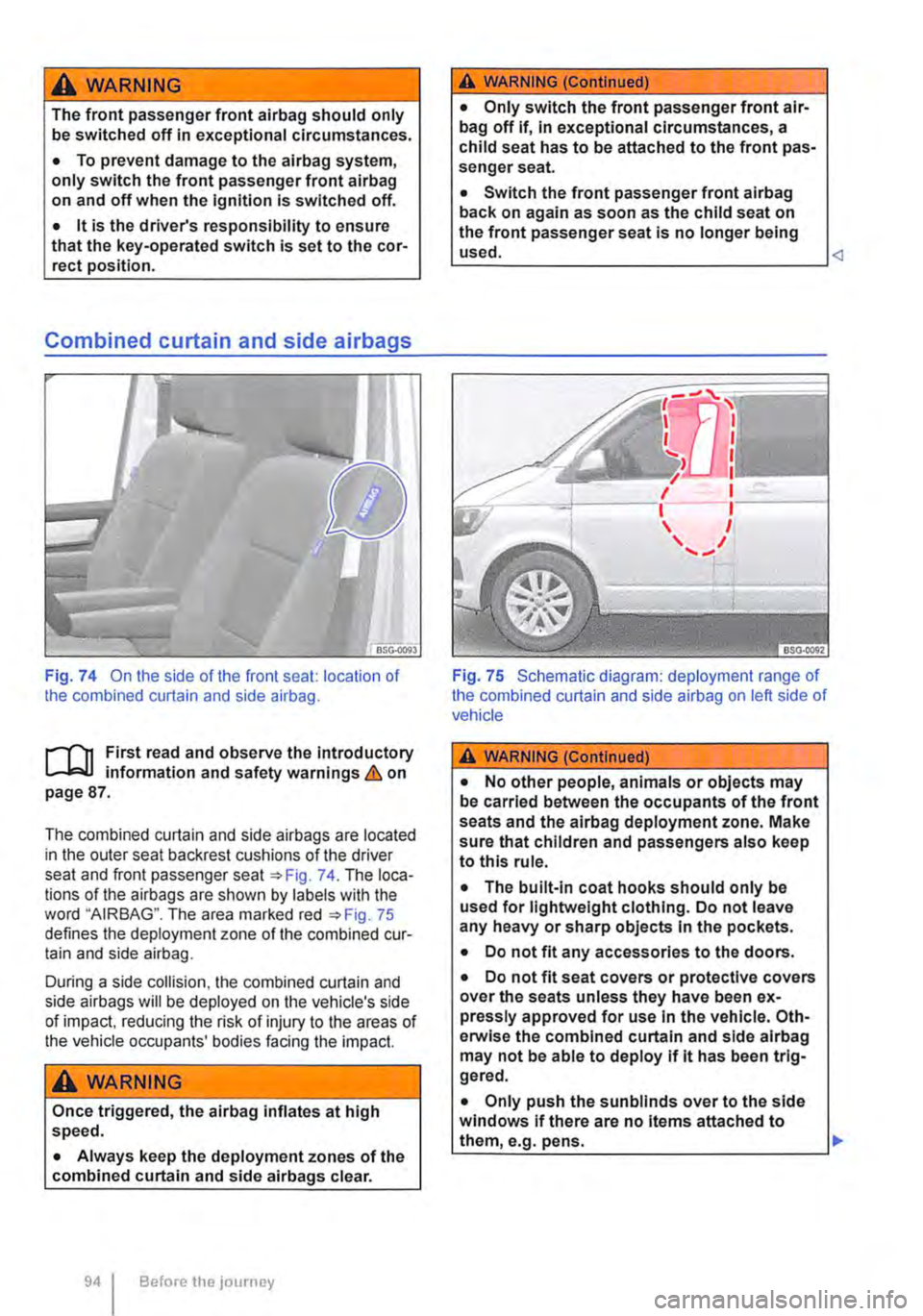
Fig. 74 On the side of the front seat: location of the combined curtain and side airbag.
l""'"'fl1 and observe the introductory L-.lr:J.J mformat1on and safety warnings & on page 87.
The combined curtain and side airbags are located in the outer seat backrest cushions of the driver seat and front passenger seat =:oFig. 74. The loca-tions of the airbags are shown by labels with the word "AIRBAG". The area marked red =:oFig. 75 defines the deployment zone of the combined cur-tain and side airbag.
During a side collision, the combined curtain and side airbags will be deployed on the vehicle's side of impact, reducing the risk of injury to the areas of the vehicle occupants' bodies facing the impact.
A WARNING
Once triggered, the airbag inflates at high speed.
• Always keep the deployment zones of the combined curtain and side airbags clear.
94 Before the journey
A WARNING (Continued)
• Only switch the front passenger front air-bag off if, In exceptional circumstances, a child seat has to be attached to the front pas-senger seat.
• Switch the front passenger front alrbag back on again as soon as the child seat on the front passenger seat is no longer being used.
Fig. 75 Schematic diagram: deployment range of the combined curtain and side airbag on left side of vehicle
A WARNING (Continued)
• No other people, animals or objects may be carried between the occupants of the front seats and the airbag deployment zone. Make sure that children and passengers also keep to this rule.
• The built-in coat hooks should only be used for lightweight clothing. Do not leave any heavy or sharp objects In the pockets.
• Do not fit any accessories to the doors.
• Do not fit seat covers or protective covers over the seats unless they have been ex-pressly approved for use In the vehicle. Oth-erwise the combined curtain and side alrbag may not be able to deploy If lt has been trig-gered.
• Only push the sunblinds over to the side windows if there are no Items attached to them, e.g. pens. .,..
Page 97 of 486
![VOLKSWAGEN TRANSPORTER 2010 Owners Manual Basic information on fitting and using child seats
A AIRBAG
(®
(!]
c:::J
BTT·I20J
Fig. 77 Airbag information sticker on the sun vi-sor.
r""(n First read and observe the introductory L.....J VOLKSWAGEN TRANSPORTER 2010 Owners Manual Basic information on fitting and using child seats
A AIRBAG
(®
(!]
c:::J
BTT·I20J
Fig. 77 Airbag information sticker on the sun vi-sor.
r""(n First read and observe the introductory L.....J](/manual-img/18/55787/w960_55787-96.png)
Basic information on fitting and using child seats
A AIRBAG
(®
(!]
c:::J
BTT·I20J
Fig. 77 Airbag information sticker on the sun vi-sor.
r""'('n First read and observe the introductory L.....Ja,U information and safety warnings & on page 96.
Information on fitting a child seat
Observe the following general information when fit-ling a child seat. This information is relevant what-ever child seat securing system is being used.
• Read and follow the instructions provided by the child seat manufacturer =:-&.
• Whenever possible, fit child seats to one of the rear seats on the front passenger side so that chil-dren can exit the vehicle on the kerb side.
• Deactivate the front passenger front airbag if fit-ting a rear-facing child seat on the front passenger seat.
• If a child seat is fitted on the front passenger seat, move the backrest to the upright position. slide the seat back as far as it will go, and set the seat height adjustment and belt height adjuster to the highest position.
• When fitting a child seat on the vehicle's rear seats, leave as much unencumbered space as possible around the child seat. If necessary, adjust the position of the relevant front seat. When doing so, ensure that the driver or front passenger can stili maintain a correct sitting position =:-page 61.
• Adjust the seat backrest angle so that the child seat lies flush against the backrest.
• When using child seats with a backrest, remove the vehicle head restraints and stow them safely in the vehicle =:-page 61. Reinstall the head restraint after the child seat has been removed.
Airbag sticker
The vehicle may be provided with stickers giving key information about the front passenger front air-bag. The information on these stickers may vary from country to country. The stickers may be at-tached on the sun visor for the driver and/or front passenger=:-Fig. 77.
11 is essential to note the warning information shown on these stickers before installing a rear-facing child seat =:-&.
Risks involved in carrying children on the front passenger seat
If you are using a rear-facing child seat, the front passenger front airbag can cause critical or poten-tially fatal injuries when it inflates =:-&.
Rear-facing child seat may only be used on the front passenger seat if the front passenger front airbag has been deactivated. An indicator lamp in the centre console lights up steadily when the front passenger front airbag has been effectively deacti-vated. Deactivating the front passenger front air-bag =:-page 87.
If using a front-facing child seat, do not deacti-vate the front passenger front airbag.
When fitting a child seat, make sure that it is as far away as possible from the front passenger airbag. The front passenger front airbag can cause severe injuries when it inflates =:-&.
Some child seats are not suitable for use on the front passenger seat. Any child seat fitted on the front passenger seat must be specially authorised by the manufacturer for this use in vehicles with front and side airbags. Volkswagen dealers hips keep an up-to-date list of authorised child seats.
Risks presented by side airbags
Any child on the front passenger seat may be hit on the head and severely injured by the front side airbag inflating =:-&.
If you use a rear-facing child seat on the front passenger seat the child in it is at increased risk of sustaining critical or fatal injuries In the event of an accident.
• Deactivate the front passenger front air-bag. If the front passenger front airbag can-not be deactivated no rear-facing child seat may be used. 11>
Sitting correctly and safely
Page 99 of 486
Not every child will fit in the child seat specified for their weight group. Likewise, not every seat will fit in every vehicle. Therefore it is vital to check that the child fits properly in their child seat and that the child seat can be securely fastened in the vehicle.
Child seat approval categories
Child seats can be classified as universal, semi-universal or vehicle-specific (all in accordance with regulation ECE-R 44), or as i-Size (in accordance with regulation ECE-R 129).
• Universal: child seats with universal approval are approved for use in all vehicles. No type list is required. ISOFIX child seats with universal appro-val must also be securing using a strap over the top of the vehicle seat (top tether).
• Semi-universal: semi-universal approval re-quires other safety devices for attaching the seat (that require additional testing) in addition to the
Securing systems
1""111 First read and observe the introductory L-J,::.U information and safety warnings & on page 96.
Different countries use different securing systems for safely fitting child seats in the vehicle.
Key terms for securing systems
• ISO FIX: ISOFIX is a standardised securing sys-tem for fitting child seats in the vehicle quickly and safely. The SOFIX attachment system creates a rigid connection between the child seat and the car body.
Any compatible child seat has two rigid attachment arms that click into ISOFIX attachment points at the bottom of the backrest. The ISOFIX securing system as described here is specific to the EU =:o page 100. An upper strap (top tether) and/or support leg may sometimes have to be used in ad-dition to the ISO FIX anchor points described above.
• Three-point automatic seat belt. lt is better to secure child seats using the ISOFIX system, if available, rather than with a three-point automatic seat belt =>page 102.
standard requirements for universal approval. Child seats with semi-universal approval come with a type list. The seats should only be used in vehi-cles that are included on this list.
• Vehicle-specific: child seats with vehicle spe-cific approval must have undergone dynamic test-ing in each model of vehicle for which it is ap-proved. These child seats also come with a type list.
• i-Size: child seats classified as must conform to the installation and safety requirements prescribed in regulation ECE-R 129. Contact the child seat manufacturer to find out which child seats are ap-proved for this vehicle in accordance with i-Size. <1
Additional securing points:
• Top tether: this strap at the top of the child seat is routed over the vehicle seat backrest and hooked to an anchor ring on the seat backs =:.page 101.
• Support leg: some child seats are propped up with a support leg resting on the floor of the vehi-cle. This support leg helps to prevent the child seat from tipping forward in a crash =:.&.
Recommended child seat securing systems
Volkswagen Commercial Vehicles recommends that child seats are secured as follows:
• Infant carrier or rear-facing child seat: ISO-FIX and support leg.
• Front-facing child seat: ISOFIX and top tether and possibly support leg also.
A WARNING
Incorrect use of the support leg can cause severe or fatal injuries.
• Make sure that the support leg is always correctly and safely Installed.
Sitting correctly and safely 99
Page 109 of 486
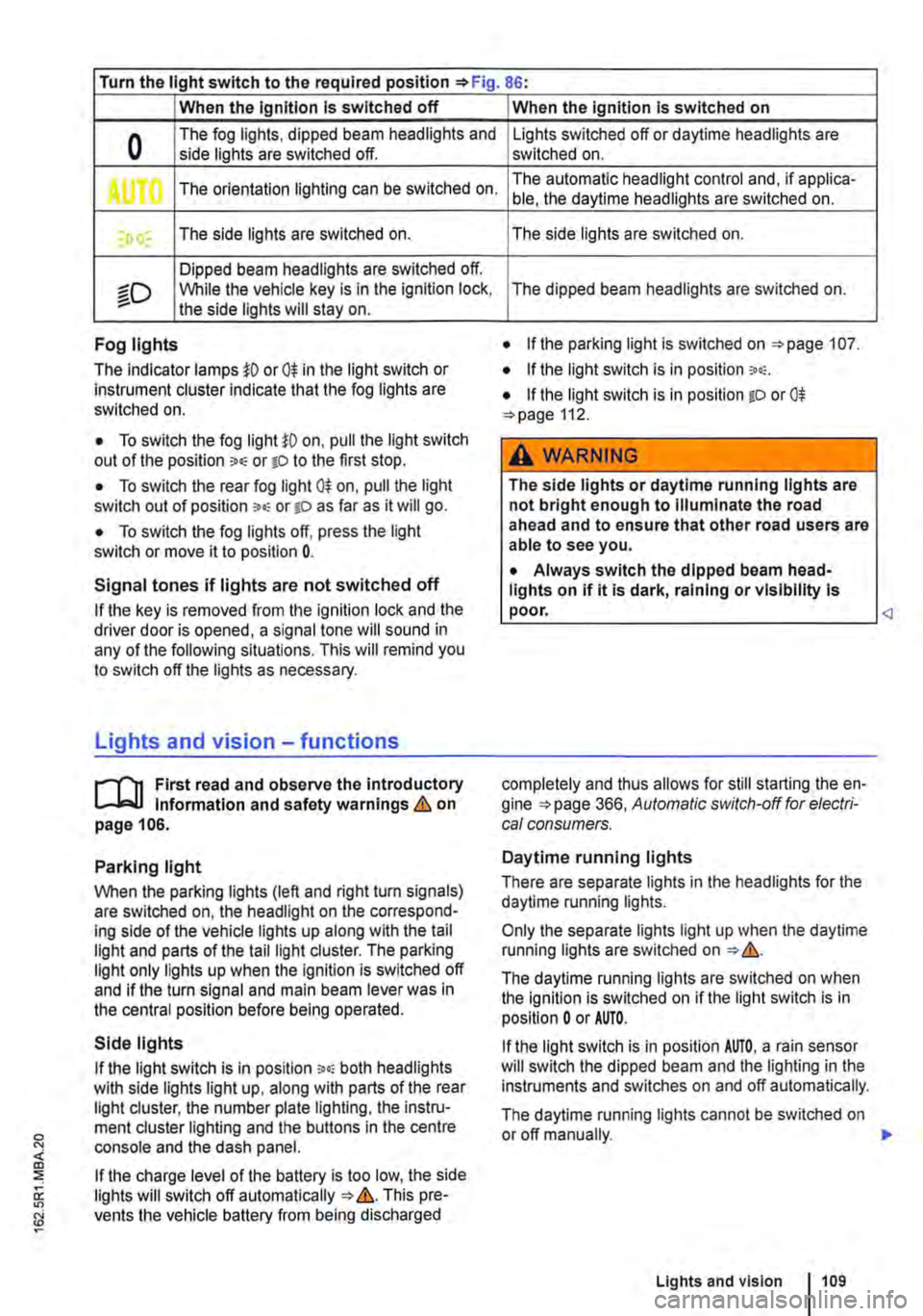
Turn the light switch to the required position 86:
When the Ignition Is switched off
0 The fog lights, dipped beam headlights and side lights are switched off.
,. The orientation lighting can be switched on.
) , The side lights are switched on.
Dipped beam headlights are switched off.
"'D While the vehicle key is in lhe ignition lock, the side lights will stay on.
Fog lights
The indicator lamps or 0$ in the light switch or Instrument cluster indicate that the fog lights are switched on.
• To switch the fog light on, pull the light switch out of the position "" or tD to the first stop.
• To switch the rear fog light 0$ on, pull the light switch out of position ,.,, or gD as far as it will go.
• To switch the fog lights off, press the light switch or move it to position 0.
Signal tones if lights are not switched off
If the key is removed from the ignition lock and the driver door is opened, a signal tone will sound in any of the following situations. This will remind you to switch off the lights as necessary.
Lights and vision -functions
1""1'11 First read and observe the introductory L-lo:.U Information and safety warnings & on page 106.
Parking light
When the parking lights (left and right turn signals) are switched on, the headlight on the correspond-ing side of the vehicle lights up along with the tail light and parts of the tail light cluster. The parking light only lights up when the Ignition is switched off and if the turn signal and main beam lever was in the central position before being operated.
Side lights
If the light switch is in position ;.o; both headlights with side lights light up, along with parts of the rear light cluster, the number plate lighting, the instru-ment cluster lighting and the buttons in the centre console and the dash panel.
If the charge level of the battery is too low, the side lights will switch off automatically &. This pre-vents the vehicle battery from being discharged
When the Ignition Is switched on
Lights switched off or daytime headlights are switched on.
The automatic headlight control and, if applica-ble, the daytime headlights are switched on.
The side lights are switched on.
The dipped beam headlights are switched on.
• If the parking light is switched on 107.
• If the light switch is in position '"'·
• If the light switch is in position iD or 0$ 112.
A WARNING
The side lights or daytime running lights are not bright enough to Illuminate the road ahead and to ensure that other road users are able to see you.
• Always switch the dipped beam head-lights on if it is dark, raining or visibility Is
completely and thus allows for still starting the en-gine 366, Automatic switch-off for electri-cal consumers.
Daytime running lights
There are separate lights in the headlights for the daytime running lights.
Only the separate lights light up when the daytime running lights are switched on &.
The daytime running lights are switched on when the ignition is switched on if the light switch is in position 0 or AUTO.
If the light switch is in position AUTO, a rain sensor will switch the dipped beam and the lighting in the instruments and switches on and off automatically.
The daytime running lights cannot be switched on or off manually. ,._
Lights and vision 1109
Page 114 of 486
Interior and reading lights
0 ( )
ITT·0116
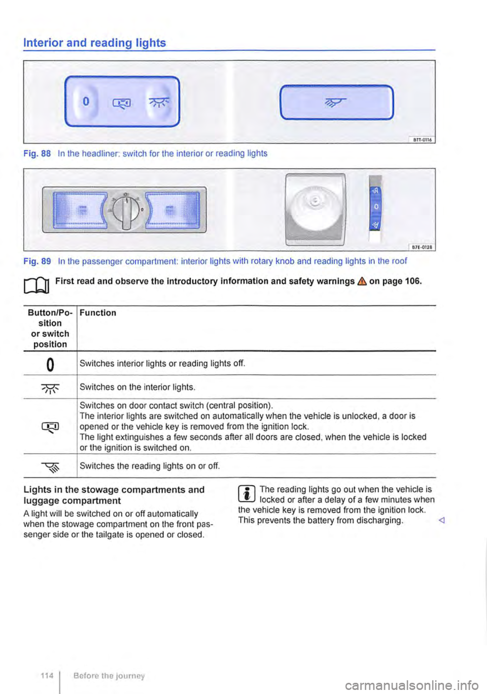
Fig. 88 In the headliner: switch for the interior or reading lights
871·01ll
Fig. 89 In the passenger compartment: interior lights with rotary knob and reading lights in the roof
[Q] First read and observe the Introductory information and safety warnings&. on page 106.
Button/Po-Function sition or switch position
0 Switches interior lights or reading lights off.
Switches on the interior lights.
Switches on door contact switch (central position). The interior lights are switched on automatically when the vehicle is unlocked, a door is opened or the vehicle key is removed from the ignition lock. The light extinguishes a few seconds after all doors are closed, when the vehicle is locked or the ignition is switched on.
Switches the reading lights on or off.
Lights in the stowage compartments and luggage compartment
A light will be switched on or off automatically when the stowage compartment on the front pas-senger side or the tailgate is opened or closed.
1141 Before the journey
m The reading lights go out when the vehicle is W locked or after a delay of a few minutes when the vehicle key is removed from the ignition lock. This prevents the battery from discharging.
Page 122 of 486
A WARNING (Continued)
asthma or similar illnesses. Immediately en-sure that there is a sufficient supply of fresh air and get out of the vehicle. If this is not possible, open all of the windows and doors.
• If the electrolyte fluid gets into the eyes or onto the skin, immediately wash the area with plenty of water for at least 15 minutes and consult a doctor.
• If the electrolyte fluid gets onto shoes or clothing, wash immediately with plenty of wa-ter for at least 15 minutes. Clean shoes and clothes thoroughly before wearing them again.
Interior mirror
A WARNING (Continued)
• If the electrolyte fluid is swallowed, imme-diately rinse the mouth with plenty of water for at least 15 minutes. Do not induce vomit-ing unless instructed to do so by a doctor. Seek medical assistance immediately.
CD
If the glass of an automatic anti-dazzle mirror is broken, electrolyte fluid can leak from the mir-ror. This fluid corrodes plastic surfaces. Re-move the fluid as soon as possible, e.g. using a wet sponge.
BSG-0101.
Fig. 99 On the windscreen: manual anti-dazzle in-terior mirror.
1"'111 First read and observe the introductory L-lo::JJ information and safety warnings & on page 121.
The driver must adjust the interior mirror so that they can see clearly through the rear window.
1221 Before the journey
The driver's rear view may be restricted or com-pletely obscured by objects such as a sun blind on the rear window, items of clothing stowed on the luggage compartment cover, or a rear window that is covered in ice, snow or dirt.
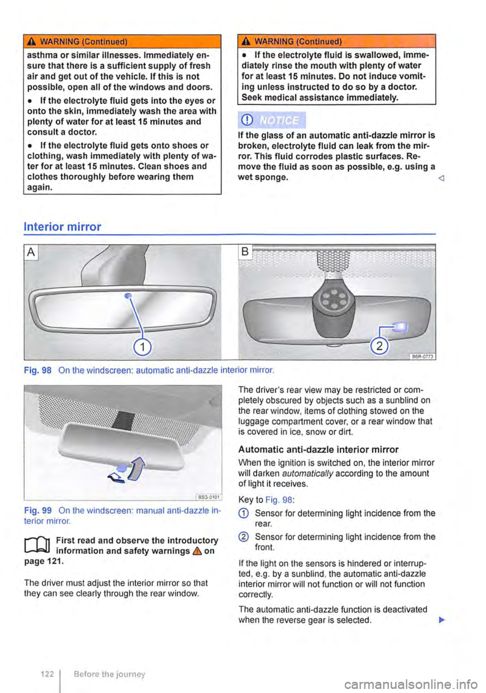
Automatic anti-dazzle interior mirror
When the ignition is switched on, the interior mirror will darken automatically according to the amount of light it receives.
Key to Fig. 98:
G) Sensor for detemnining light incidence from the rear.
® Sensor for detemnining light incidence from the front.
If the light on the sensors is hindered or interrup-ted, e.g. by a sunblind, the automatic anti-dazzle interior mirror will not function or will not function correctly.
The automatic anti-dazzle function is deactivated when the reverse gear is selected. .,..
Page 137 of 486
n11 First read and observe the introductory l-J=,IJ information and safety warnings & on page 133.
The net partition can prevent objects in the lug-gage compartment entering the passenger com-partment.
The net partition can be fitted behind the front seats or behind the 3-seat bench.
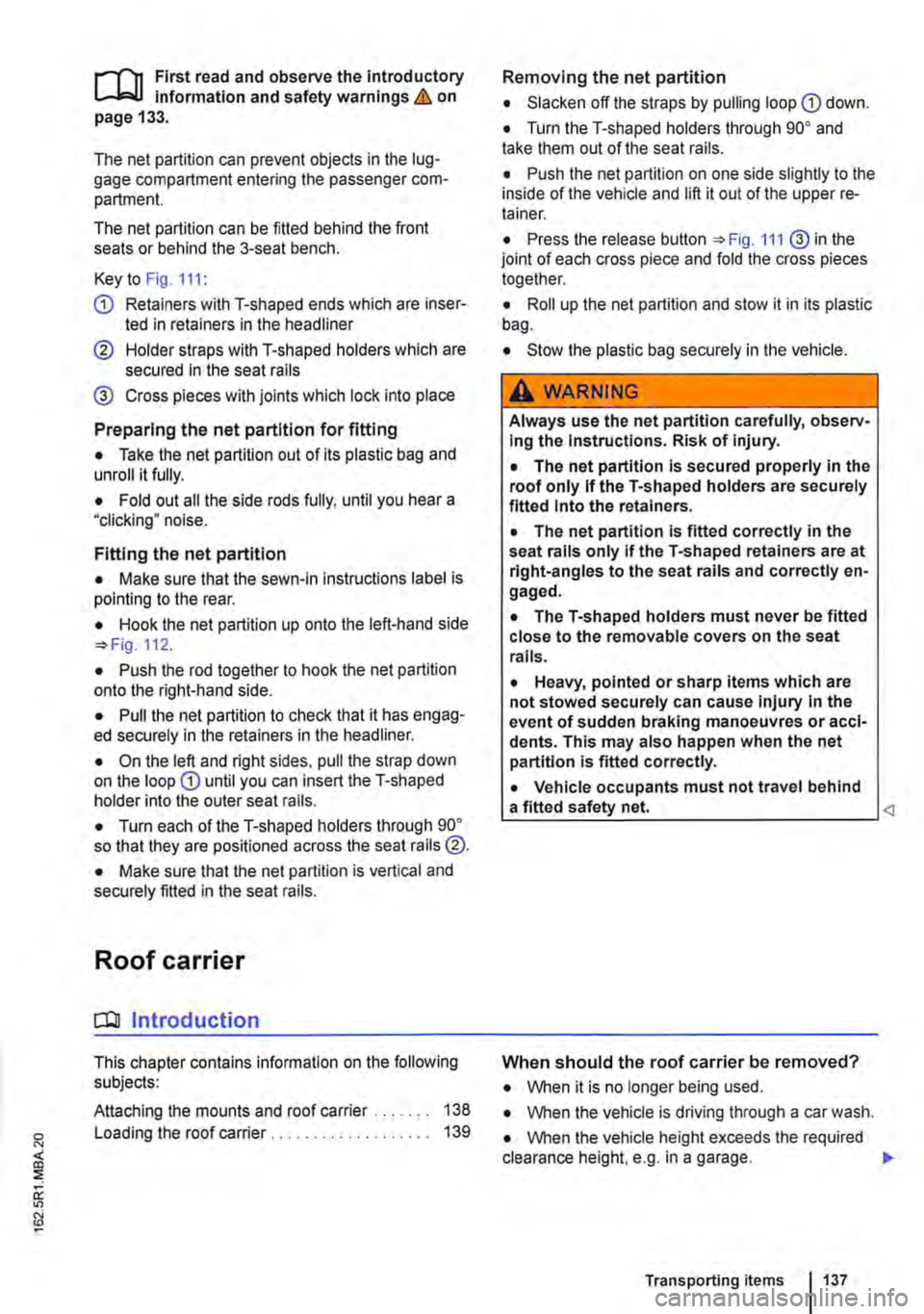
Key to Fig. 111:
® Cross pieces with joints which lock into place
Preparing the net partition for fitting
• Take the net partition out of its plastic bag and unroll it fully.
• Fold out all the side rods fully, until you hear a "clicking• noise.
Fitting the net partition
• Make sure that the sewn-in instructions label is pointing to the rear.
• Hook the net partition up onto the left-hand side
• Push the rod together to hook the net partition onto the right-hand side.
• Pull the net partition to check that it has engag-ed securely in the retainers in the headliner.
• On the left and right sides. pull the strap down on the loop G) until you can insert the T-shaped holder into the outer seat rails.
• Turn each of the T-shaped holders through 90° so that they are positioned across the seat rails @.
• Make sure that the net partition is vertical and securely fitted in the seat rails.
Roof carrier
COl Introduction
This chapter contains information on the following subjects:
Attaching the mounts and roof carrier . . . . . . . 138 Loading the roof carrier . . . . . . . . . . . . . . . . . . . 139
Removing the net partition
• Slacken off the straps by pulling loop
• Push the net partition on one side slightly to the inside of the vehicle and lift it out of the upper re-tainer.
• Press the release button 111 ® in the joint of each cross piece and fold the cross pieces together.
• Roll up the net partition and stow it in its plastic bag.
• Stow the plastic bag securely in the vehicle.
A WARNING
Always use the net partition carefully, observ-Ing the Instructions. Risk of injury.
• The net partition is secured properly in the roof only if the T-shaped holders are securely fitted Into the retainers.
• The net partition is fitted correctly in the seat rails only if the T-shaped retainers are at right-angles to the seat rails and correctly en-gaged.
• The T-shaped holders must never be fitted close to the removable covers on the seat rails.
• Heavy, pointed or sharp items which are not stowed securely can cause Injury in the event of sudden braking manoeuvres or acci-dents. This may also happen when the net partition is fitted correctly.
• Vehicle occupants must not travel behind a fitted safety net.
• When it is no longer being used.
• When the vehicle is driving through a car wash.
• When the vehicle height exceeds the required clearance height, e.g. in a garage. .,.
Transporting items 1137
Page 143 of 486
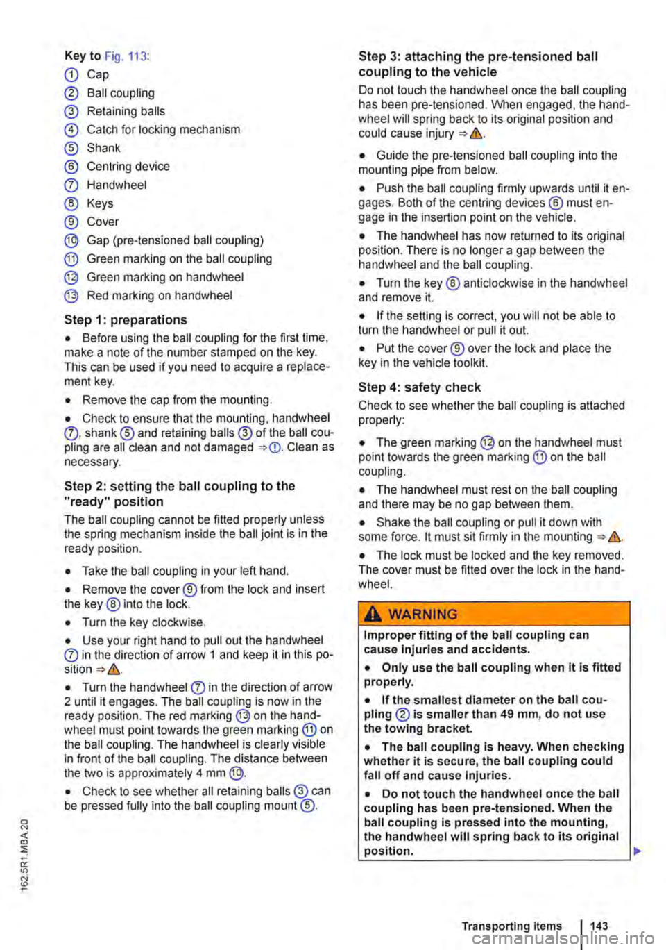
Key to Fig. 113:
Q) Cap
® Ball coupling
@ Retaining balls
@ Catch for locking mechanism
® Shank
® Centring device
0 Handwheel
® Keys
® Cover
® Gap (pre-tensioned ball coupling)
® Green marking on the ball coupling
@ Green marking on handwheel
@ Red marking on handwheel
Step 1: preparations
• Before using the ball coupling for the first time, make a note of the number stamped on the key. This can be used if you need to acquire a replace-ment key.
• Remove the cap from the mounting.
• Check to ensure that the mounting, handwheel 0. shank® and retaining balls@ of the ball cou-pling are all clean and not damaged Clean as necessary.
Step 2: setting the ball coupling to the "ready" position
The ball coupling cannot be fitted properly unless the spring mechanism inside the ball joint is in the ready position.
• Take the ball coupling in your left hand.
• Remove the cover® from the lock and insert the key ® into the lock.
• Turn the key clockwise.
• Use your right hand to pull out the handwheel 0 in the direction of arrow 1 and keep it in this po-
• Turn the handwheel 0 in the direction of arrow 2 until it engages. The ball coupling is now in the ready position. The red marking @on the hand-wheel must point towards the green marking ® on the ball coupling. The handwheel is clearly visible in front of the ball coupling. The distance between the two is approximately 4 mm @.
• Check to see whether all retaining balls @can be pressed fully into the ball coupling mount @.
Step 3: attaching the pre-tensioned ball coupling to the vehicle
Do not touch the handwheel once the ball coupling has been pre-tensioned. When engaged, the hand-wheel will spring back to its original position and could cause injury = &.
• Guide the pre-tensioned ball coupling into the mounting pipe from below.
• Push the ball coupling firmly upwards until it en-gages. Both of the centring devices ® must en-gage in the insertion point on the vehicle.
• The handwheel has now returned to its original position. There is no longer a gap between the handwheel and the ball coupling.
• Turn the key ® anticlockwise in the handwheel and remove it.
• If the setting is correct, you will not be able to turn the handwheel or pull it out.
• Put the cover® over the lock and place the key in the vehicle toolkit.
Step 4: safety check
Check to see whether the ball coupling is attached properly:
• The green marking@ on the handwheel must point towards the green marking @ on the ball coupling.
• The handwheel must rest on the ball coupling and there may be no gap between them.
• Shake the ball coupling or pull it down with some force. lt must sit firmly in the mounting = &.
• The lock must be locked and the key removed. The cover must be fitted over the lock in the hand-wheel.
A wARNING
Improper fitting of the ball coupling can cause injuries and accidents.
• Only use the ball coupling when it is fitted properly.
• If the smallest diameter on the ball cou-pling ® is smaller than 49 mm, do not use the towing bracket.
• The ball coupling is heavy. When checking whether it is secure, the ball coupling could fall off and cause injuries.
• Do not touch the handwheel once the ball coupling has been pre-tensioned. When the ball coupling is pressed into the mounting, the handwheel will spring back to its original position. ..,
Transporting items 1143