2010 VOLKSWAGEN TRANSPORTER key
[x] Cancel search: keyPage 144 of 486
A WARNING (Continued)
• If the ball coupling will not fit properly, the towing bracket should be checked by a quali-fied workshop.
• Do not use the towing bracket If the ball coupling does not engage properly or if you are unable to set it to the "ready" position.
• Do not use the towing bracket if you are unable to remove the key from the handwheel once the ball coupling has been mounted. This means that ball coupling Is not locked properly.
Removing the ball coupling
r--T'n First read and observe the Introductory L-J.:.IJ information and safety warnings & on page 139.
• Unhitch the trailer => &.
• Remove the cover =>Fig. 113 ®from the lock on the handwheel.
• Insert the key® into the lock and turn it clock-wise.
• Hold the ball coupling tightly in your left hand =>&.
• Use your right hand to pull out the handwheel 0 in the direction of arrow 1 and keep it in this po-sition.
• Turn the handwheel 0 in the direction of arrow 2 until it engages.
Hitching and connecting the trailer
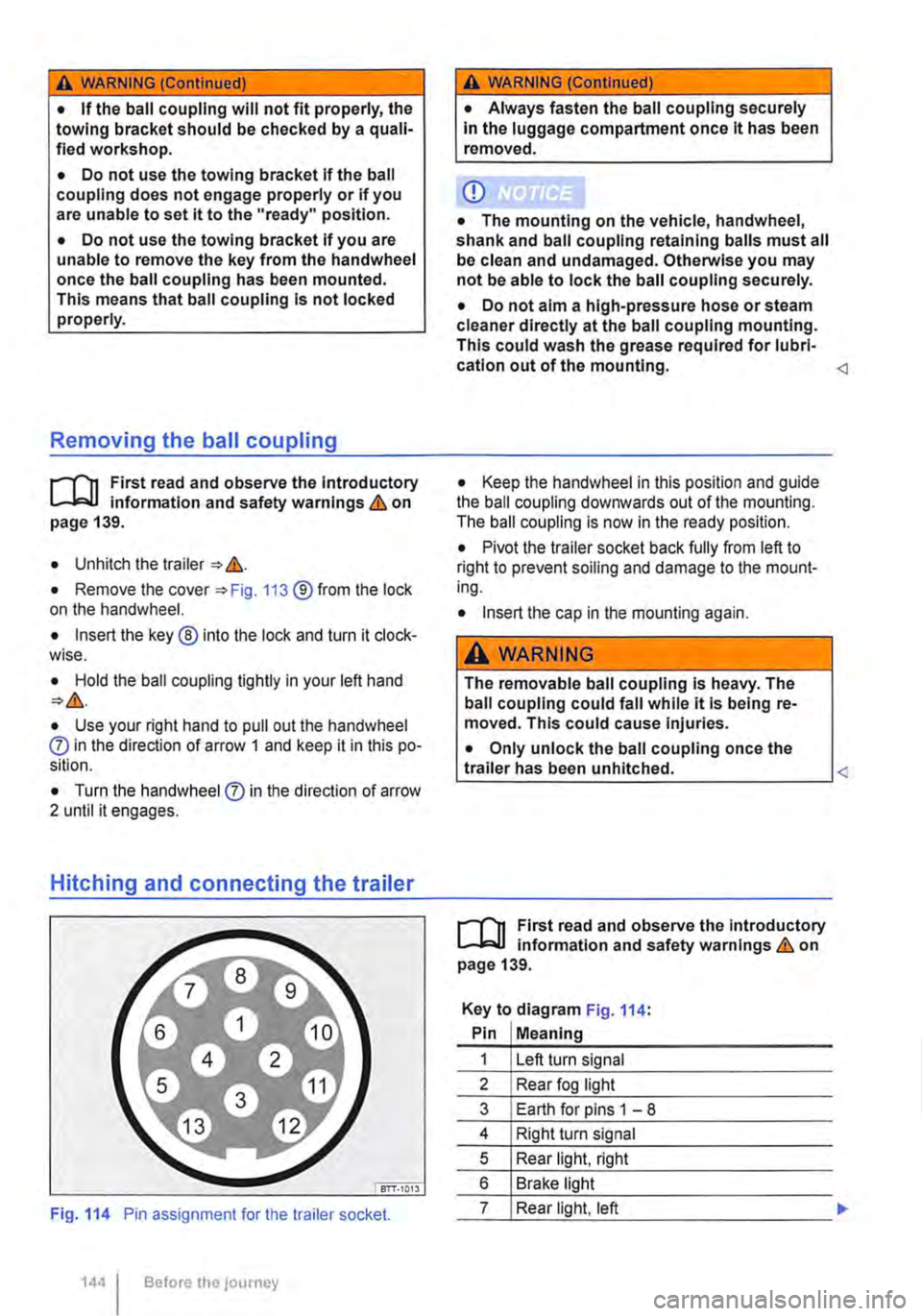
Fig. 114 Pin assignment for the trailer socket.
1441 Before the journey
A WARNING (Continued)
• Always fasten the ball coupling securely In the luggage compartment once it has been removed.
CD
• The mounting on the vehicle, handwheel, shank and ball coupling retaining balls must all be clean and undamaged. Otherwise you may not be able to lock the ball coupling securely.
• Do not aim a high-pressure hose or steam cleaner directly at the ball coupling mounting. This could wash the grease required for lubri-cation out of the mounting.
• Pivot the trailer socket back fully from left to right to prevent soiling and damage to the mount-ing.
• Insert the cap in the mounting again.
A WARNING
The removable ball coupling Is heavy. The ball coupling could fall while it Is being re-moved. This could cause Injuries.
• Only unlock the ball coupling once the L-tr_a_ile_r_h_a_s __ be_e_n __ u_n_hi_tc_h_e_d_. ____________
r--T'n First read and observe the Introductory L-J.:.IJ information and safety warnings & on page 139.
Key to diagram Fig. 114:
Pin Meaning
1 Left turn signal
2 Rear fog light
3 Earth for pins 1 -8
4 Right turn signal
5 Rear light, right
6 Brake light
7 Rear light, left
Page 145 of 486

Key to diagram Fig. 114:
Pin Meaning
8 Reversing light
9 Permanent live
10 Charging cable plus
11 Earth pin 10, charging cable
12 Not assigned
13 Earth pin 9, permanent live
Trailer socket
A 13-pin trailer socket makes the electrical connec-tion between the towing vehicle and the trailer. When the engine is running, electrical consumers in the trailer are supplied with voltage (charging ca-ble) via the electrical connection (pin 10 of the trail-er socket). If required, the charging cable charges the caravan's battery.
When a trailer is electrically detected, electrical consumers in the trailer are supplied with voltage (permanent live) via the electrical connection (pin 9). Permanent live supplies a trailer's interior lighting for example. Electrical consumers such as a caravan refrigerator are supplied with voltage on-ly when the engine is running (pin 1 0).
To avoid overloading the electrical system, do not inter-connect the three earth wires (pins 3, 11 and 13).
If the trailer has a 7 -pin plug you will need to use a suitable adapter cable. Pin 10 (charging cable) is then without function.
Emergency breakaway cable
Always fasten the trailer's emergency breakaway cable properly to the towing vehicle. Leave enough slack in the emergency breakaway cable so that the vehicle can still drive around corners. However the emergency breakaway cable should not drag along the ground while you are driving.
Trailer rear lights
Ensure that the trailer lights work properly and meet legal requirements. Do not exceed the maxi-mum power consumption for the trailer 142.
Connection to the anti-theft alarm
The trailer is integrated in the anti-theft system if the following conditions are fulfilled:
• When the vehicle has a factory-fitted anti-theft alarm and a factory-fitted towing bracket.
• When the trailer is electrically connected to the towing vehicle via the trailer socket.
• When the vehicle and trailer electric systems are functional, fault-free and undamaged.
• When the vehicle is locked with the vehicle key and the anti-theft alarm is active.
When the vehicle is locked, the alarm will be trig-gered as soon as the electrical connection to the trailer is interrupted.
Always switch off the anti-theft alarm when a trailer is being hitched or unhitched. The tilt sensor could otherwise trigger an alarm unnecessarily.
Trailer with LED rear lights
For technical reasons, trailers with LED tail lights cannot be integrated into the anti-theft alarm sys-tem.
When the vehicle is locked, the alarm is not trig-gered as soon as the electrical connection to the trailer with LED rear lights is interrupted.
A WARNING
Any electrical cables that are not connected properly could cause a power surge to the trailer. This could cause faults tn the entire vehicle electronics system and also lead to accidents and serious Injuries.
• All work on the electric system should be carried out by a qualified workshop.
• Never connect the trailer's electrical sys-tem directly to the electrical connections of the tail lights or to other sources of electrici-ty.
CD
If you park the trailer using the support wheel or other trailer supports, disconnect the trailer from the vehicle. The vehicle could rock up and down if the load changes or if there is damage to the tyres. If this happens, a great deal of force will be exerted on the towing bracket and trailer, which could lead to damage to the vehi-cle and trailer.
CD
Maximum power consumption of the trailer should not be exceeded. Otherwise, the vehicle electrical system could be damaged.
m If there is a fault in the vehicle or trailer elec-L.:!.J trical systems or in the anti-theft alarm, have the systems checked by a qualified workshop.
m If the engine is not running and electrical L.:!.J equipment is switched on in the trailer via the trailer socket, the vehicle battery will discharge. .,.
Transporting Items 145
Page 151 of 486
A WARNING (Continued)
• Never stow lighters in stowage areas or compartments or on other surfaces In the ve-hicle. Cigarette lighters may self-Ignite on high-temperature surfaces, especially in sum-mer.
CD
• Hard objects on the shelf can chafe against the wires of the heating element In the rear win-dow and cause damage.
• Objects stored In the vehicle that are made from transparent materials, such as glasses, magnifying glasses or transparent suction cups on the windows, can concentrate the sun's rays and thus cause damage to the vehi-cle.
r:F1 Always ensure that the ventilation openings W between the rear window and the stowage area are uncovered to allow stale air to escape from the vehicle.
r('n First read and observe the introductory L-Jc.lJ information and safety warnings.& on page 150.
There is a stowage compartment in the centre con-sole, which. depending on the vehicle equipment level, may have a cover flap.
To open, press the button on the cover flap. The stowage compartment opens automatically.
To close, press the cover down until it engages. Do not press the button while doing this.
Depending on the vehicle equipment level, there may be open stowage compartments under the vents on the dash panel.
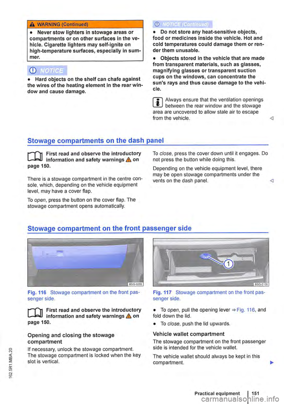
Fig. 116 Stowage compartment on the front pas-senger side.
r('n First read and observe the introductory L-Jc.lJ Information and safety warnings.& on page 150.
Opening and closing the stowage compartment
If necessary, unlock the stowage compartment. The stowage compartment is locked when the key slot is vertical.
Fig. 117 Stowage compartment on the front pas-senger side.
• To open, pull the opening lever =:.Fig. 116, and fold down the lid.
• To close. push the lid upwards.
Vehicle wallet compartment
The stowage compartment on the front passenger side is intended for the vehicle wallet.
The vehicle wallet should always be kept in this compartment. .,.
Practical equipment 1151
Page 157 of 486
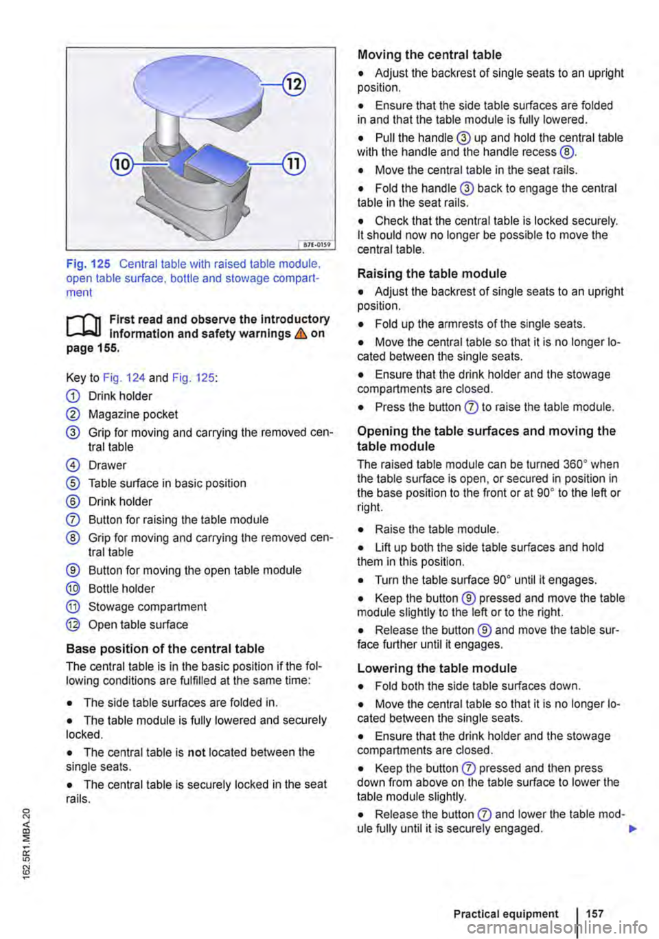
Fig. 125 Central table with raised table module, open table surface. bottle and stowage compart-ment
r-1'11 First read and observe the Introductory l.-Jr:-lJ Information and safety warnings & on page 155.
Key to Fig. 124 and Fig. 125:
G) Drink holder
0 Magazine pocket
® Grip for moving and carrying the removed cen-tral table
@ Drawer
® Table surface in basic position
® Drink holder
0 Button for raising the table module
® Grip for moving and carrying the removed cen-tral table
® Button for moving the open table module
® Bottle holder
® Stowage compartment
@ Open table surface
Base position of the central table
The central table is in the basic position if the fol-lowing conditions are fulfilled at the same time:
• The side table surfaces are folded in.
• The table module is fully lowered and securely locked.
• The central table is not located between the single seats.
• The central table is securely locked in the seat rails.
Moving the central table
• Adjust the backrest of single seats to an upright position.
• Ensure that the side table surfaces are folded in and that the table module is fully lowered.
• Pull the handle® up and hold the central table wilh the handle and the handle recess @.
• Move the central table in the seat rails.
• Fold the handle® back to engage the central table in the seat rails.
• Check that the central table is locked securely. lt should now no longer be possible to move the central table.
Raising the table module
• Adjust the backrest of single seats to an upright position.
• Fold up the armrests of the single seats.
• Move the central table so that it is no longer lo-cated between the single seats.
• Ensure that the drink holder and the stowage compartments are closed.
• Press the button 0 to raise the table module.
Opening the table surfaces and moving the
table module
The raised table module can be turned 36o• when the table surface is open, or secured in position in the base position to the front or at go• to the left or rig hi.
• Raise lhe table module.
• Lift up both the side table surfaces and hold them in this position.
• Turn the table surface go• until it engages.
• Keep the button ® pressed and move the table module slightly to the left or to the right.
• Release the button ® and move the table sur-face further until it engages.
Lowering the table module
• Fold both the side table surfaces down.
• Move the central table so that it is no longer lo-cated between the single seats.
• Ensure that the drink holder and the stowage compartments are closed.
• Keep the button 0 pressed and then press down from above on the table surface to lower the table module slightly.
• Release the button 0 and lower lhe table mod-ule fully until it is securely engaged. .,.
Practical equipment 1157
Page 168 of 486
Controls on the LCD screen
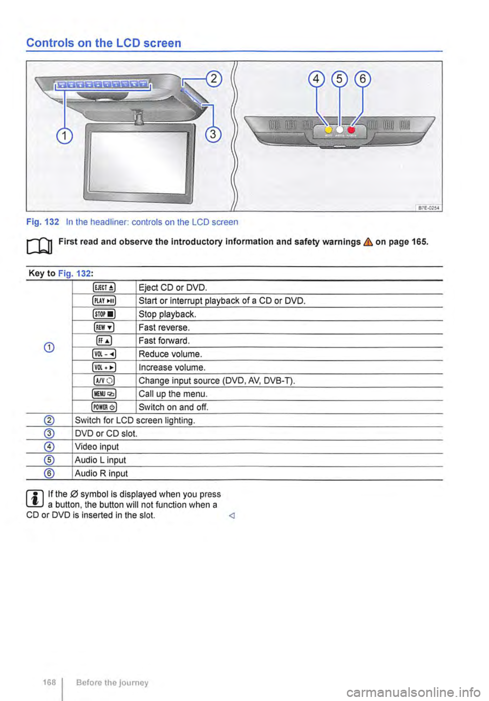
Fig. 132 In the headliner: controls on the LCD screen
m First read and observe the Introductory Information and safety warnings & on page 165.
Key to Fig 132·
Eject CD or DVD.
illAY •uJ Start or interrupt playback of a CD or DVD.
lsTor•l Stop playback.
IREW ,.] Fast reverse.
G) ([;) Fast forward.
lvOl--.) Reduce volume.
lvOl • •I Increase volume.
IA/YO) Change input source (DVD, AV, DVB-T).
lllli.JQ,) Call up the menu.
IPOm) Switch on and off.
® Switch for LCD screen lighting.
@ DVD or CD slot.
® Video input
® Audio L input
® Audio R input
rll If the 0 symbol is displayed when you press L!.J a button. the button will not function when a CD or DVD is inserted in the slot.
Page 169 of 486
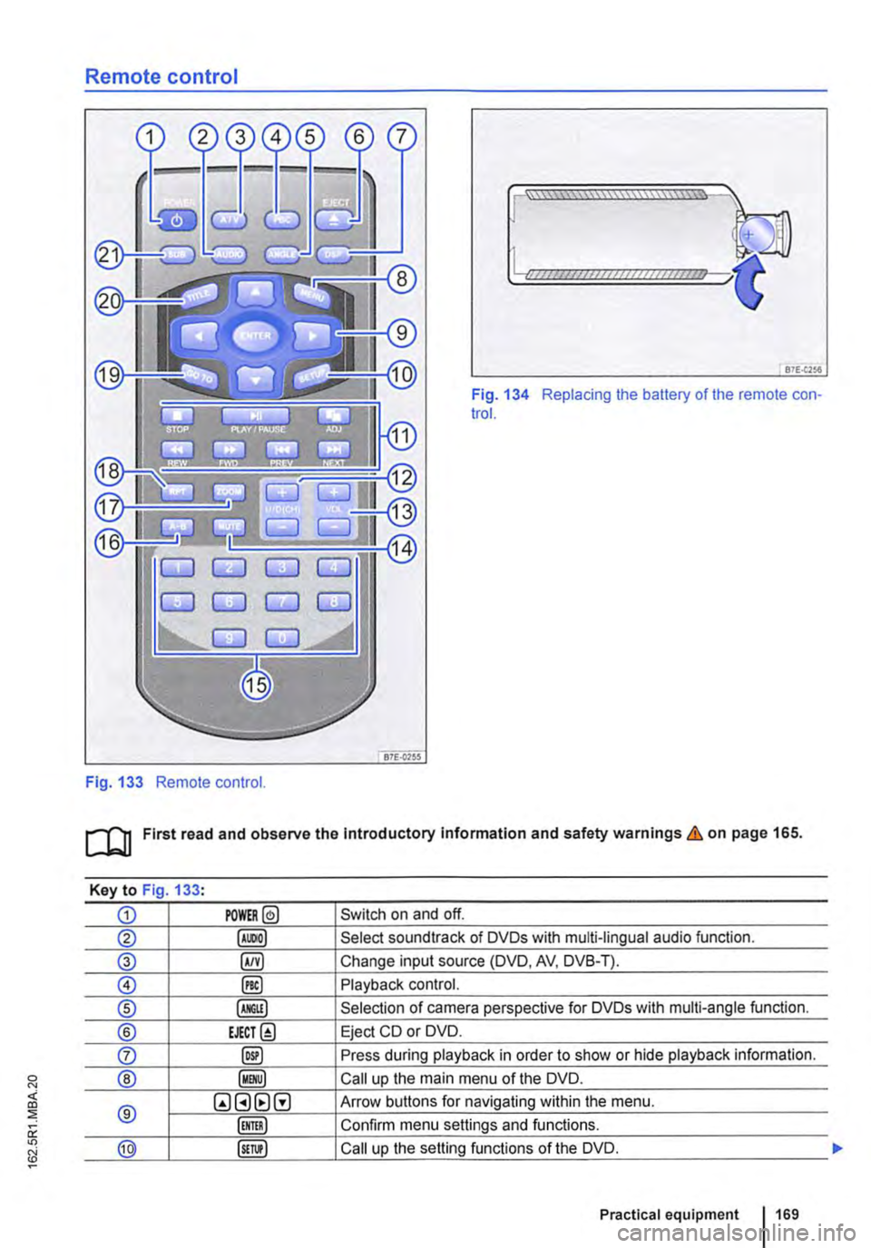
Remote control
Fig. 133 Remote control.
[::::::::::::::::::::::vm
81£.(256
Fig. 134 Replacing the battery of the remote con-trol.
[QJ First read and observe the Introductory Information and safety warnings & on page 165.
Key to Fig 133·
CD POWER@ Switch on and off.
@ Select soundtrack of DVDs with multi-lingual audio function.
® §) Change input source (DVD, AV, DVB-T).
0 @) Playback control.
® Selection of camera perspective for DVDs with multi-angle function.
® EJECT@ Eject CD or DVD.
0 @) Press during playback in order to show or hide playback information.
® Call up the main menu of the DVD.
® QGHtlG Arrow buttons for navigating within the menu.
Confirm menu settings and functions.
@ Call up the setting functions of the DVD.
Practical equipment 169
Page 170 of 486
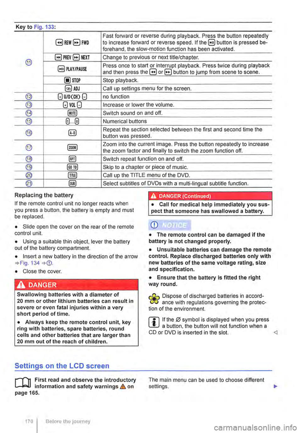
Key to Fig 133·
8REW8FWD Fast forward or reverse during playback. Press the button repeatedly to increase forward or reverse speed. If the§) button is pressed be-forehand, the slow-motion function has been activated.
@ §)PREY 81£XT Change to previous or next title/chapter.
§) PLAY /PAUSE Press once to start or interrupt playback. Press twice during playback and then press the B or 8 button to jump from scene to scene.
@STOP Stop playback.
Call up settings menu for the screen.
© (!) U/D(CH) Q no function
@ (!)VO!.Q Increase or lower the volume.
®l Switch sound on and off.
@ (ij ... (i) Numerical buttons
® @ Repeat the section selected between the first and second time the button was pressed.
@ Zoom into the current image. Press the button repeatedly to increase the zoom factor and finally to switch the zoom function off.
@ @) Switch repeat function on and off.
@ Skip to a chapter or piece of music.
@ §D Call up the TITLE menu of the DVD.
@ @ Select subtitles of DVDs with a multi-lingual subtitle function.
Replacing the battery
If the remote control unit no longer reacts when you press a button. the battery is empty and must be replaced.
• Slide open the cover on the rear of the remote control unit.
• Using a suitable thin object, lever the battery out of the battery compartment.
• Insert a new battery in the direction of the arrow 134
• Close the cover.
Swallowing batteries with a diameter of 20 mm or other lithium batteries can result in severe or even fatal injuries within a very short period of time.
• Always keep the remote control unit, key ring with batteries, spare batteries, round cells and other batteries that are larger than 20 mm out of the reach of children.
Settings on the LCD screen
rl'11 First read and observe the introductory L-W.f information and safety warnings & on page 165.
170 I Before the journey
• Call for medical help immediately you sus-pect that someone has swallowed a battery.
CD
• The remote control can be damaged if the battery is not changed properly.
• Unsuitable batteries can damage the remote control. Replace discharged batteries only with new batteries of the same voltage rating, size and specification.
• Ensure that the battery Is fitted the right way round.
Dispose of discharged batteries in accord-W ance with regulations governing the protec-tion of the environment.
r::l If the 0 symbol is displayed when you press l!J a button, the button will not function when a CD or DVD is inserted in the slot.
Page 171 of 486
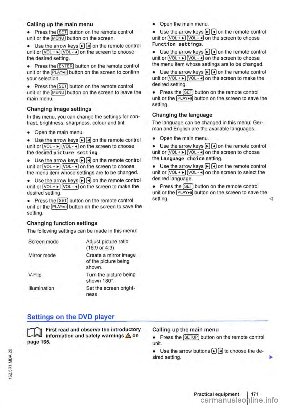
Calling up the main menu
• Press button on the remote control unit or the MENU button on the screen.
• Use the arr(w keyJ (8 G on the remote control unit or lvoL + ... ) VOL-.. on the screen to choose the desired setting.
unit or the PLAY>tl button on the screen to confirm your selection.
• Press the @m button on the remote control unit or the jMENUJ button on the screen to leave the main menu.
Changing image settings
In this menu, you can change the settings for con-trast, brightness, sharpness, colour and tint.
• Open the main menu.
• Use the arr(w keys) (8 G on the remote control unit or jvoL + ... ) VOL-.. on the screen to choose the desired picture setting.
• Use the arr(w keys) (8 G on the remote control unit or lvoL + ... ) voL-.. on the screen to choose the menu item whose settings are to be changed.
• Use the arr(w keys) (8 G on the remote control unit or lvOL + ... ) VOL-.. on the screen to make the desired setting.
unit or the PLAY•u button on the screen to save the setting.
Changing function settings
The following settings can be made in this menu:
Screen mode
Mirror mode
V-Fiip
Illumination
Adjust picture ratio (16:9 or 4:3)
Create a mirror image of the picture being shown.
Turn the picture being shown 180°.
Set the screen bright-ness
Settings on the DVD player
r--("'n First read and observe the introductory L.-J.:.I.I information and safety warnings & on page 165.
• Open the main menu.
• Use the arr(w keys) (8 G on the remote control unit or lvoL + ... ) VOL-.. on the screen to choose Function settings.
• Use the arr(w keyJ (8 G on the remote control unit or lvoL + ... ) VOL-.. on the screen to choose the menu item whose settings are to be changed.
• Use the arr(w keys) (8 G on the remote control unit or lvoL + ... ] VOL-.. on the screen to make the desired setting.
unit or the PLAY>tl button on the screen to save the setting.
Changing the language
The language can be changed in this menu: Ger-man and English are the available languages.
• Open the main menu.
• Use the arr(w keys) (8 G on the remote control unit or lvoL + ... ) voL-.. on the screen to choose the Language choice setting.
• Use the arr(w keys) (8 G on the remote control unit or lvoL + ... ) VOL-.. on the screen to select the desired language.
• Press the SET button on the remote control unit or the setting.
Calling up the main menu
• Press the !SETUP) button on the remote control unit.
• Use the arrow buttons (8 G to choose the de-sired setting. .,.
Practical equipment 1171