Page 17 of 199
 Owners Manual Instruments and Indicator/Warning Lights
16
Avoid high engine speeds du ring the driving time and before the engine has reached
operating temperature page 118.
For the sake of the environment
Shi")
Instruments and Indicator/Warning Lights
16
Avoid high engine speeds du ring the driving time and before the engine has reached
operating temperature page 118.
For the sake of the environment
Shifting up early helps you sa ve fuel and reduce the operating noise of your vehicle.SpeedometerThe speedometer shows the current speed of the car.Engine coolant temperature DisplayThe coolant temperature gauge page 15, fig. 15 operates only when the ignition
is switched on.
In order to avoid any damage to the engine, please pay attention to the following notes
regarding the temperature ranges:
Cold range
If the pointer is in the left-hand area of the scale it means that the engine has not yet
reached its operating temperatur e. Avoid running at high engine speeds, at full throttle
and at severe engine loads.
The operating range
The engine has reached its operating temper ature as soon as the pointer moves into
the mid-range of the scale. The pointer may also move further to the right at high
engine loads and high outside temperatures. This is not critical provided the warning
symbol
in the instrument cluster does not flash.
If the symbol in the instrument cluster flashes it means that either the coolant
temperature is too high or the coolant level is too low. Observe the guidelines
page 25, “Coolant temperature/coolant level ”.
WARNING
Pay attention to the warning notes page 140, “Working in the engine
compartment” before opening the bonnet and inspecting the coolant level.
Caution
Additional headlights and other attached components in front of the fresh air inlet
impair the cooling effi ciency of the coolant. There is then a risk of the engine over-
heating at high outside temper atures and high engine loads!Fuel gaugeThe fuel gauge page 15, fig. 15 only works when the ignition is switched on.
The fuel tank has a capacity of about 55 litres. The warning symbol
in the instrument
cluster lights up when the pointer reaches the reserve marking. There are now about 9
litres of fuel remaining in the tank. This symbol is a reminder for you, that you must
refuel .
An acoustic signal sounds as an additional reminder.
Caution
Never run the fuel tank completely empty! The irregular supply of the fuel system can
lead to irregular running of the engine. Un burnt fuel may get into the exhaust system
and damage the catalytic converter.Counter for distance drivenThe distance which you have driven with yo ur vehicle is shown in kilometres (km). In
some countries the measuring unit “mile” is used.
Reset button
Hold the reset button page 15, fig. 15 pressed for approx. 1 second. The trip
counter is reset to zero.
Trip counter for distance driven
The trip counter shows the distance driven since the time the trip counter was last
erased. The trip is shown in steps of 100 metres or 1/10 of a mile.
A3
A6
A5
s2bs.2.book Page 16 Monday, September 27, 2010 9:53 AM
Page 18 of 199
 Owners Manual Instruments and Indicator/Warning Lights17
Using the system
Safety
Driving Tips
General Maintenance
Breakdown assistance
Technical Data
Odometer
The odometer indicates the total distance in
kilometre")
Instruments and Indicator/Warning Lights17
Using the system
Safety
Driving Tips
General Maintenance
Breakdown assistance
Technical Data
Odometer
The odometer indicates the total distance in
kilometres or miles which the vehicle has
been driven.
Fa u l t d i s p l a y
If there is a fault in the instrument cluster Error will appear in the display. Contact a
specialist garage.
WARNING
Never seek to adjust the trip counter for distance driven while driving for safety
reasons!
Note
If the display of the second speed is acti vated in mph or km/h, this speed is shown
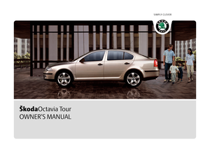
instead of the odometer on the display.Service Interval DisplayService Interval Display
Before the next service interval a key symbol
and the remaining kilometres are
indicated after switching on the ignition fig. 16. At the same time, a display appears
regarding the remaining days until the next service interval.
The kilometre indicator or the days indicator reduces in steps of 100 km. or days until
the service due date is reached. A flashing key symbol
and the text
Service appears in the display for 20 seconds
as soon as the due date for the service is reached.
Resetting Service Interval Display
It is only possible to reset the Service Interval Display, if a service message or at least a
pre-warning is shown on the disp lay of the instrument cluster.
We recommend having this resetting performed by a specialist garage.
The specialist garage:
resets the memory of the display after the appropriate inspection,
makes an entry in the Service schedule,
affix the sticker with the entry of the following service interval to the side of the
dash panel on the driver's side.
This can be reset as follows: Press the button page 15, fig. 15 and keep it pressed
down, start the ignition, release the butt on and turn it to the left or right.Caution
We recommend you ask a specialist garage to reset the service interval display. Incor-
rectly setting the service interval display can cause problems to the vehicle.
Note
Never reset the display between service intervals otherwise this may result in
incorrect readouts.
information is retained in the Service Inte rval Display also after the battery of the
vehicle is disconnected.
The service interval display will need to be re-configured if the instrument cluster
is replaced. Contact a specialist garage. This work is carried out by a specialist garage.
The data displayed is the same after resetting the display with flexible service inter-
vals (QG1) using the reset button as that for a vehicle with fixed service intervals (QG2).
We therefore recommend having the Service In terval Display reset only by an author-
ised Škoda Service Partner who is familiar with the procedure for resetting the display
with a vehicle system tester.
Please refer to the brochure Service schedule for extensive information about the
service intervals.
Fig. 16 Service Interval Display: Note
A5
s2bs.2.book Page 17 Monday, September 27, 2010 9:53 AM
Page 19 of 199
 Owners Manual Instruments and Indicator/Warning Lights
18
Digital clockYou can set the time with the rotary knob page 15, fig. 15.
Select the information which you wish to change by turning the button and c")
Instruments and Indicator/Warning Lights
18
Digital clockYou can set the time with the rotary knob page 15, fig. 15.
Select the information which you wish to change by turning the button and carry
out the change of the selected information by pressing the button.
WARNING
The clock should not be adjusted while dr iving for safety reasons but only when
the vehicle is stationary!Recommended gear*An information for the selected gear fig. 17 is shown in the display of the instru-
ment cluster.
In order to minimise the fuel consumptio n, a recommendation for shifting into
another gear is indicated in the display.
If the control unit recognises that it is a ppropriate to change the gear, an arrow is
shown in the display. The arrow points upwards or downwards depending on whether
it is recommended to switch to a higher or lower gear.
At the same time, the recommended gear is indicated instead of the currently selected
gear .
Multi-functional indica tor (onboard computer)*IntroductionThis data from the multi-functional indicator appears in the display fig. 18 .
The multi-functional indicator offers you a range of useful information.
Note
In certain national versions the displays a ppear in the Imperial system of measures.Memory
A5
A5
Fig. 17 Recommended gear
AA
AB
AA
The outside temperature
page 20
Driving time
page 20
Current fuel consumption
page 20
Average fuel consumption
page 20
Range
page 20
Distance driven
page 20
Average speed
page 21
Current speed*
page 21
Warning against excessive speeds*
page 21
Fig. 18 Multi-functional indicator
s2bs.2.book Page 18 Monday, September 27, 2010 9:53 AM
Page 20 of 199
 Owners Manual Instruments and Indicator/Warning Lights19
Using the system
Safety
Driving Tips
General Maintenance
Breakdown assistance
Technical Data
The multi-functional indicator is equipped with two automatic me")
Instruments and Indicator/Warning Lights19
Using the system
Safety
Driving Tips
General Maintenance
Breakdown assistance
Technical Data
The multi-functional indicator is equipped with two automatic memories. The
selected memory is displayed in the middle of the display field
page 18, fig. 18 .
The data of the single-trip memory (memory 1) is shown if a 1 appears in the display.
A 2 shown in the display means that data relates to the total distance memory
(memory 2).
Switching over the memory takes place with the button fig. 19 on the windshield
wiper lever.
Single-trip memory (memory 1)
The single-trip memory collates the driving information from the moment the ignition
is switched on until it is switched off. New data will also flow into the calculation of the
current driving information if the trip is continued within 2 hours after switching off
the ignition. The memory will be is automatically erased, on the other hand, if the trip
is interrupted for more than 2 hours .
Total-trip memory (memory 2)
The total distance driven memory gathers da ta from any number of individual jour-
neys up to a total of 19 hours and 59 minutes driving or 1.999 kilometres driven. The
memory is deleted when either of these limits is reached and the calculation starts
from anew.
The total-trip memory will not, contrary to the single-trip memory, be deleted after a
period of interr uption of driving of 2 hours.
Note
All information in the memory 1 and 2 is erased if the battery of the vehicle is
disconnected.
Operating with the buttons on the windshield wiper leverThe rocker and the button are located in the grip of the window wiper lever
fig. 19 .Selecting the memory– Tapping the rocker on the windshield wiper lever allows you to select the
desired memory.Selecting the functions– Press the rocker up or down. In this way, call up in sequence the individual func- tions of the multi-functional indicator.Setting function to zero– Select the memory you want.
– Press button .
The following readouts of the selected me mory will be set to zero by button :
average fuel consumption,
distance driven,
average speed,
Driving time.
AB
Fig. 19 Multi-functional indicator:
Control elements
AA
AB
AB
AA
AB
AB
s2bs.2.book Page 19 Monday, September 27, 2010 9:53 AM
Page 21 of 199
 Owners Manual Instruments and Indicator/Warning Lights
20
You can only operate the multi-functional in dicator when the ignition is switched on.
After the ignition is switched on, the function displayed is the one")
Instruments and Indicator/Warning Lights
20
You can only operate the multi-functional in dicator when the ignition is switched on.
After the ignition is switched on, the function displayed is the one which you last
selected before switching off the ignition.Outside temperatureThe outside temperature appears in the disp lay when the ignition is switched on.
If the outside temperature drops below +4 °C, a snow flake symbol (warning signal for
ice on the road) appears before the temperature indicator and a warning signal
sounds. After pressing the rocker on the windshield wiper lever page 19, fig. 19 ,
the function which was shown last is indicated.
WARNING
Do not only rely upon the information given on the outside temperature display
that there is no ice on the road. Please note that black ice may also be present
on the road surface even at temperatures around +4 °C - warning, drive with
care!Driving timeThe driving time which has elapsed since the memory was last erased, appears in the
display. If you wish to measure the driving ti me as of a particular time, you must set the
memory to zero at this moment in time by pressing the button page 19, fig. 19
on the windshield wiper lever for longer than 1 second.
The maximum distance indicated in both memories is 19 hours and 59 minutes. The
indicator is set back to null if this period is exceeded.Current consumptionThe current fuel consumption level is shown in the display in litres/100 km. This infor-
mation can help you to adapt your style of driving to the fuel consumption you wish to
achieve.
The display appears in litres/hour if the vehicle is stationary or driving at a low speed.
The indicated value will be updated every 0.5 seconds while you are driving.
Average fuel consumptionThe average fuel consumption since the memory was last erased is shown in the
display in litres/100 km page 18. This information can help you to adapt your style
of driving to the fuel cons umption you wish to achieve.
If you wish to determine the average fuel consumption over a certain period of time,
you must set the memory at the start of th e new measurement to zero using the button
on the windshield wiper lever. A zero appears in the display for the first 100 m you
drive after erasing the memory.
The indicated value will be updated every 5 seconds while you are driving.
Note
The amount of fuel consumed will not be indicated.RangeThe estimated range in kilometres is shown on the display. It indicates the distance you
can still drive with your vehicle based on th e current level of fuel in the tank for the
same style of driving.
The readout is shown in steps of 10 km. After lighting up of the indicator light for the
fuel reserve the display is shown in steps of 5 km.
The fuel consumption for the last 50 km is taken as a basis for calculating the range. If
you drive in a more economical manner, the range will be increased accordingly.
If the memory is set to zero (after disco nnecting the battery), the fuel consumption of
10 ltr./100 km is calculated for the range; afterwards the value is adapted accordingly
to the style of driving.Distance drivenThe distance driven since the memory was last erased appears in the display
page 18. If you wish to calculate the distance driven as of a particular time, you must
erase the memory at this moment in time by pressing the button on the windshield
wiper lever page 19, fig. 19.
AA
AB
AB
AB
s2bs.2.book Page 20 Monday, September 27, 2010 9:53 AM
Page 22 of 199
 Owners Manual Instruments and Indicator/Warning Lights21
Using the system
Safety
Driving Tips
General Maintenance
Breakdown assistance
Technical Data
The maximum distance indicated in both switch positions is 1,999")
Instruments and Indicator/Warning Lights21
Using the system
Safety
Driving Tips
General Maintenance
Breakdown assistance
Technical Data
The maximum distance indicated in both switch positions is 1,999 km. The indicator is
set back to null if this
period is exceeded.
Average speedThe average speed since the memory was last erased is shown in the display in
km/hour page 18. If you wish to determine the average speed over a certain period
of time, you must set the memory at the start of the new measurement to zero using
the button on the windshield wiper lever page 19, fig. 19 .
Dashes appear in the display for the first 100 m you drive after erasing the memory.
The indicated value will be updated every 5 seconds while you are driving.Current speed*The current speed is displayed on the display. It is identical to the display on the
tachometer (speedometer) page 15, fig. 15 .
Note
If the display of the second speed is activa ted in mph, the current speed* is not indi-
cated in km/h on the display.Warning against excessive speeds*This function enables you to set a speed li mit and will notify you if you exceed this
speed limit.Configuring the speed limit while the vehicle is stationary– With switch page 19, fig. 19 , choose the menu point Warning against
excessive speeds .
– Press the switch to activate configurat ion of the speed limit (the value flashes).
– Use switch to set the required speed limit, e.g. 50 km/h.
– Confirm the speed limit that was set with button , or wait 5 seconds until the setting is saved automatically (the value stops flashing). In this way you can set the limit in 5 km/h steps.
Configuring the speed limit while the vehicle is moving– With switch , choose the menu point
Warning against excessive speeds.
– Drive e.°g at a speed of 50 km/h.
– Press the switch to accept the curr ent speed as the speed limit (the value
flashes).
If you wish to change the speed limit that was set, it is changed in 5 km/h intervals (e.g.
the accepted speed of 47 km/h increases to 50 km/h or decreases to 45 km/h).
– Confirm the speed limit that was set by pressing button again, or wait 5 seconds until the setting is saved automati cally (the value stops flashing).Changing or erasing the speed limit– With switch , choose the menu point Warning against excessive speeds.
– When you press the switch ag ain, the speed limit is erased.
– Pressing the switch a further time activates the change mode for the speed limit.
If you exceed the configured speed, an ac oustic signal will sound as a warning. A
Warning against excessive speeds appears together with the set limit on the display.
The set speed limit remains stored even after switching off the ignition.
WARNING
Pay attention primarily to the traffic situation! As the driver you are fully
responsible for road safety.
AB
A2
AA
AB
AA
AB
AA
AB
AB
AA
AB
AB
s2bs.2.book Page 21 Monday, September 27, 2010 9:53 AM
Page 23 of 199
Instruments and Indicator/Warning Lights
22
Warning lightsOverview
The warning lights indicate certain functions or faults.
Fig. 20 Instrument cluster with warning lights
Turn signal lights (to the left) page 23
Turn signal lights (to the right) page 23
Fog lights* page 23
Main beam light page 23
Low beam light page 24
Rear fog light page 24
Cruise control system* page 24
Failure of the light bulbs page 24
Airbag system page 24
Control system for exhaust page 24
Electromechanical power steering page 24
Engine oil pressure page 25
EPC fault light (petrol engine) page 25
Glow plug system (diesel engine) page 25
s2bs.2.book Page 22 Monday, September 27, 2010 9:53 AM
Page 24 of 199
 Owners Manual Instruments and Indicator/Warning Lights23
Using the system
Safety
Driving Tips
General Maintenance
Breakdown assistance
Technical Data
WARNING
If you do not pay attention to the warning lights co")
Instruments and Indicator/Warning Lights23
Using the system
Safety
Driving Tips
General Maintenance
Breakdown assistance
Technical Data
WARNING
If you do not pay attention to the warning lights coming on and the corre-
sponding descriptions and warning notes, this may result in severe body inju-
ries or major vehicle damage.
The engine compartment of your car is a hazardous area. There is a risk of
injuries, scalding, accidents and fire wh en working in the engine compartment,
e.g. inspecting and replenishing oil and other fluids. It is also essential to
observe all warnings page 140, “Working in the engine compartment”.Note
The arrangement of the indicator lights depends on the model version. The
symbols shown in the following functional description are to be found as indicator
lights in the instrument cluster.
Operational faults are shown in the instrument cluster as red symbols (priority 1 -
danger) or yellow symbol s (priority 2 - warning).
Turn signal system
Either the left
or right
indicator light flashes depending on the position of the turn
signal lever.
The indicator light flashes at twice its normal rate if a turn signal light fails.
Switching off the hazard warning light system is switched on will cause all of the turn
signal lights as well as both indicator lights to flash.
Further information about the turn signal system page 44.
Fog lights*
The warning light
comes on when the fog lights are operating page 43.
Main beam
The indicator light
comes on when the main beam is selected or also when the
headlight flasher is operated.
Coolant temperature/coolant level page 25
Traction control system (TCS) page 26
Electronic stability programme (ESP)* page 26
Switch off the Traction control system (TCS); page 26
Tyre pres su re* page 27
Antilock brake system (ABS) page 27
Bonnet page 27
Seat belt warning light page 28
Brake pad wear* page 28
Boot lid page 28
Open door page 28
Brake system page 28
Dynamo page 28
Engine oil level page 29
Fuel reserve page 29
s2bs.2.book Page 23 Monday, September 27, 2010 9:53 AM
 1
1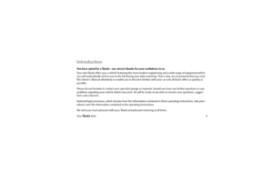 2
2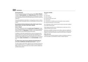 3
3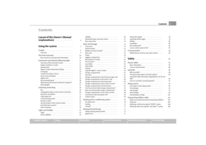 4
4 5
5 6
6 7
7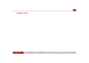 8
8 9
9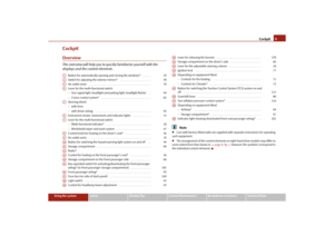 10
10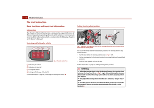 11
11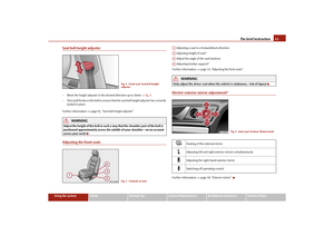 12
12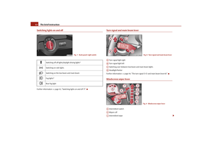 13
13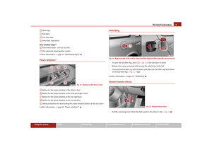 14
14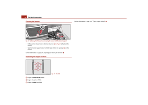 15
15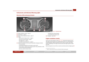 16
16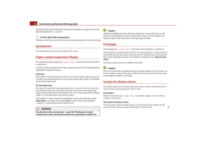 17
17 18
18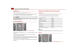 19
19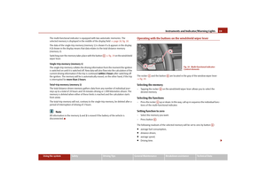 20
20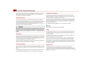 21
21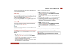 22
22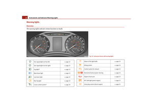 23
23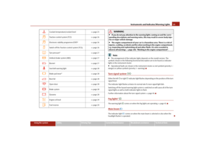 24
24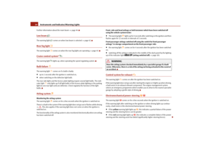 25
25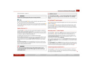 26
26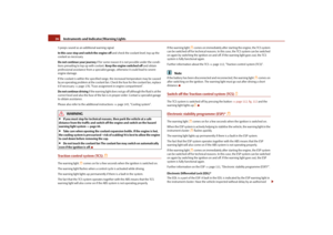 27
27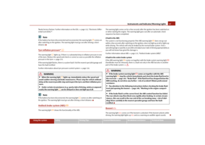 28
28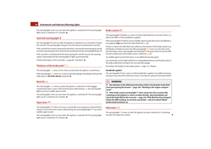 29
29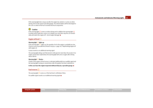 30
30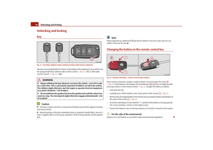 31
31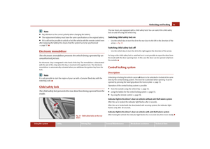 32
32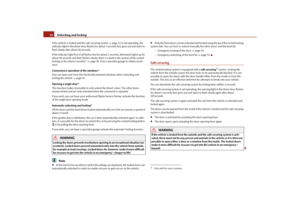 33
33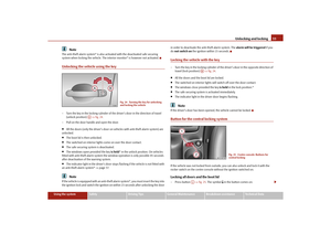 34
34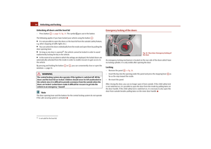 35
35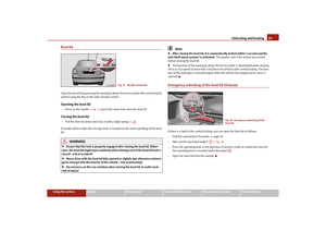 36
36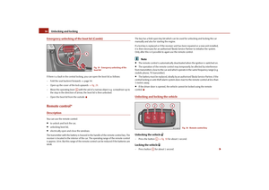 37
37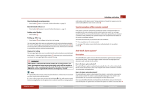 38
38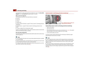 39
39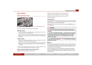 40
40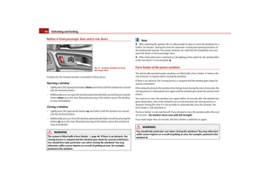 41
41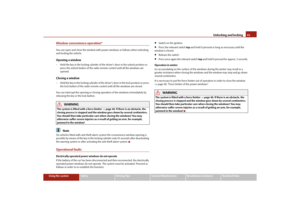 42
42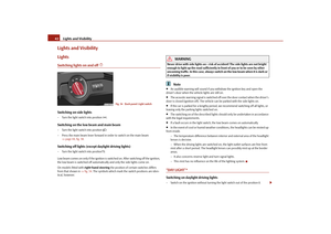 43
43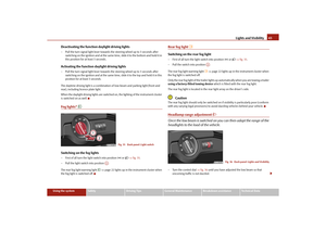 44
44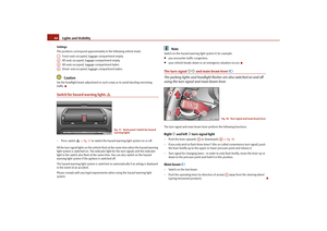 45
45 46
46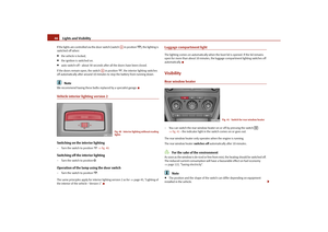 47
47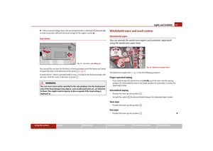 48
48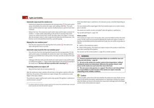 49
49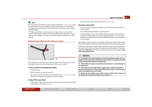 50
50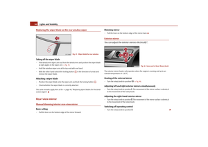 51
51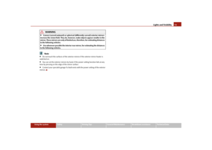 52
52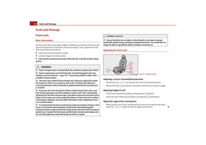 53
53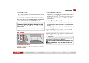 54
54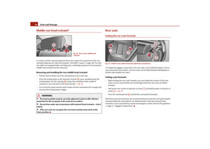 55
55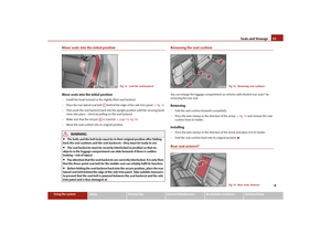 56
56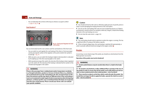 57
57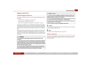 58
58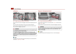 59
59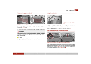 60
60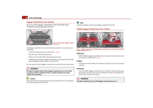 61
61 62
62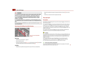 63
63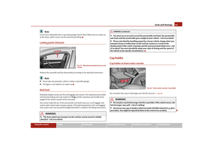 64
64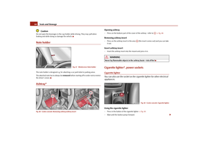 65
65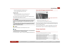 66
66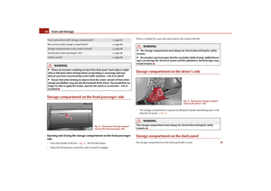 67
67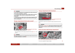 68
68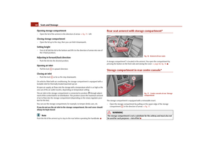 69
69 70
70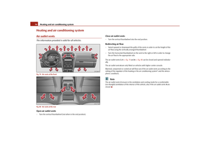 71
71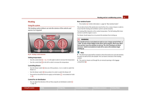 72
72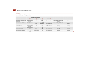 73
73 74
74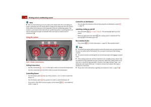 75
75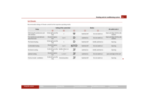 76
76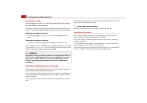 77
77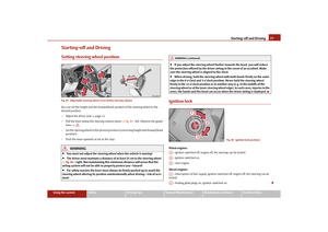 78
78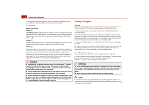 79
79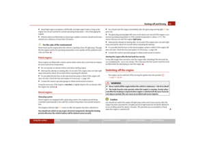 80
80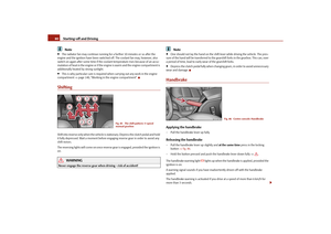 81
81 82
82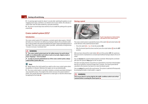 83
83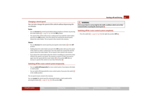 84
84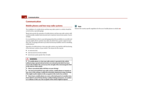 85
85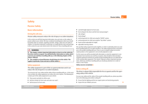 86
86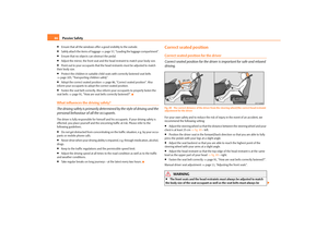 87
87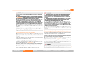 88
88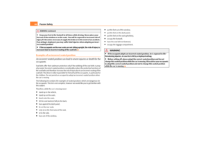 89
89 90
90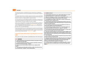 91
91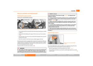 92
92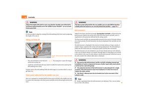 93
93 94
94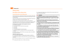 95
95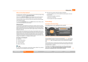 96
96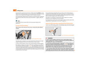 97
97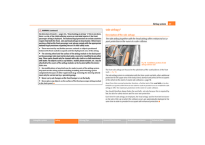 98
98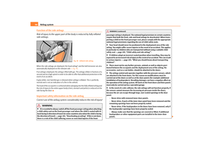 99
99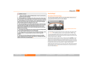 100
100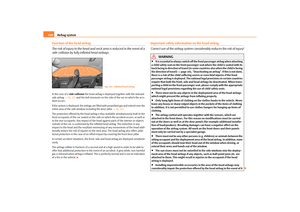 101
101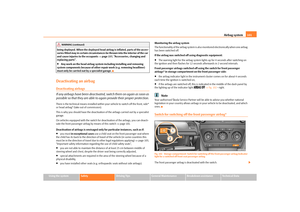 102
102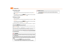 103
103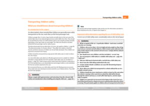 104
104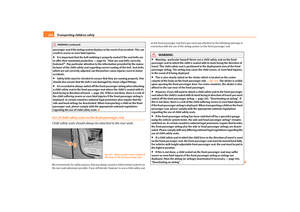 105
105 106
106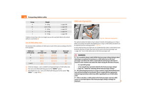 107
107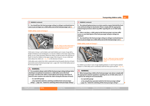 108
108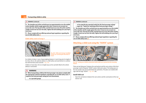 109
109 110
110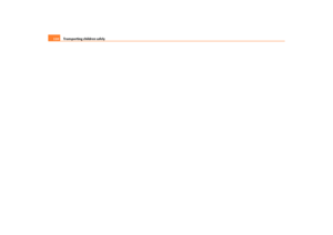 111
111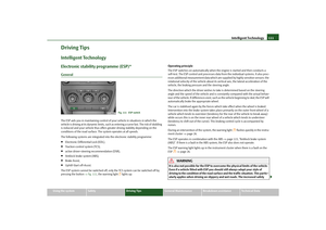 112
112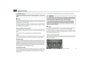 113
113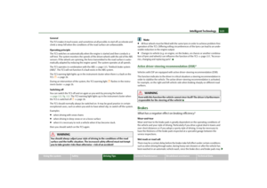 114
114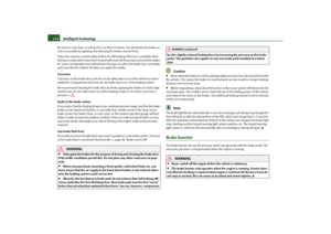 115
115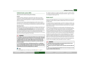 116
116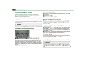 117
117 118
118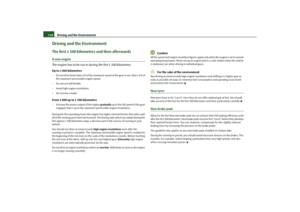 119
119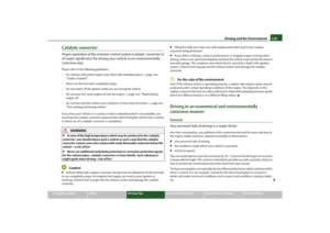 120
120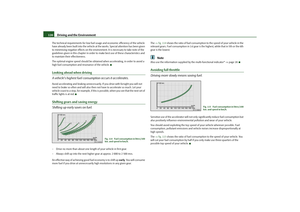 121
121 122
122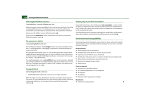 123
123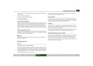 124
124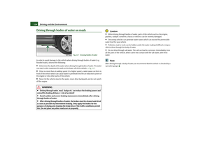 125
125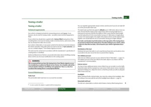 126
126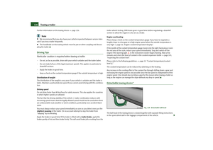 127
127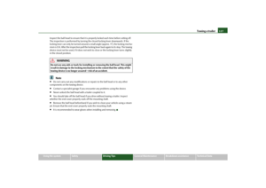 128
128 129
129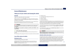 130
130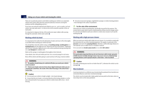 131
131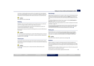 132
132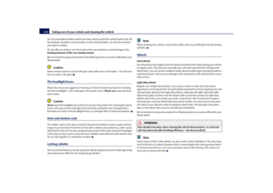 133
133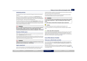 134
134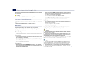 135
135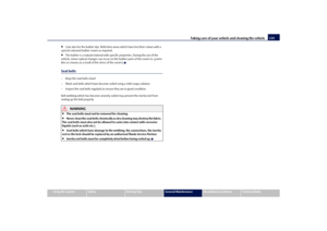 136
136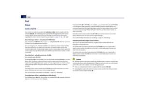 137
137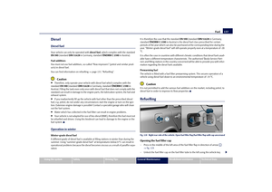 138
138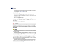 139
139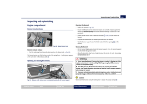 140
140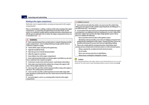 141
141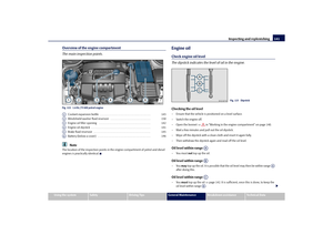 142
142 143
143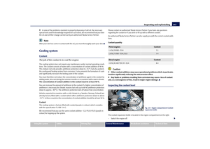 144
144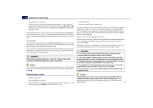 145
145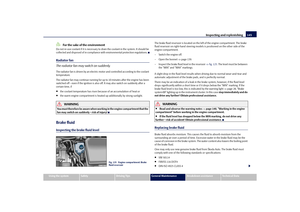 146
146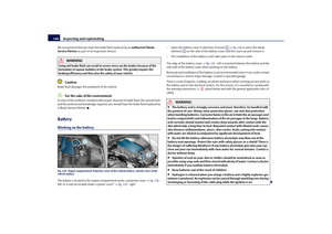 147
147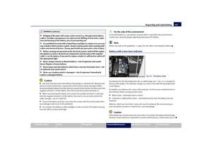 148
148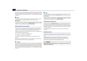 149
149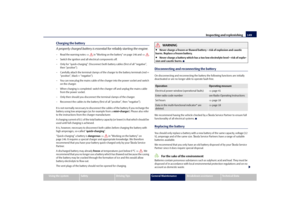 150
150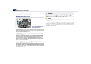 151
151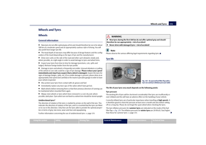 152
152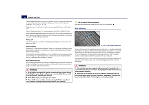 153
153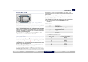 154
154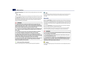 155
155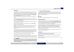 156
156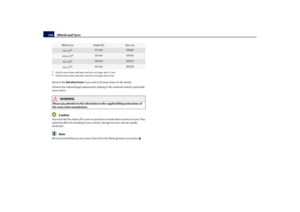 157
157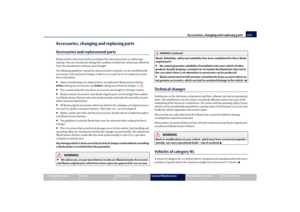 158
158 159
159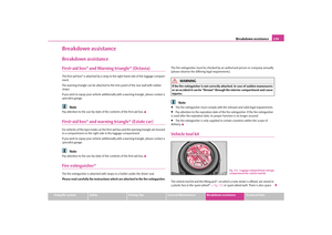 160
160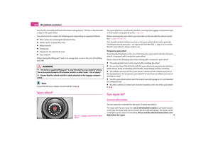 161
161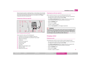 162
162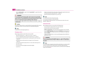 163
163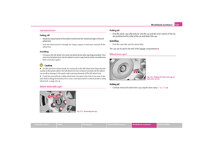 164
164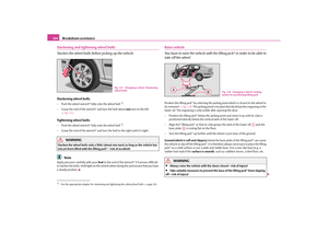 165
165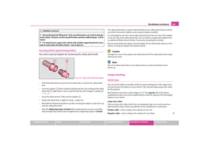 166
166 167
167 168
168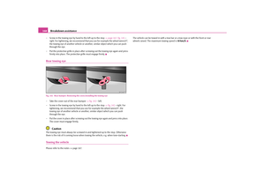 169
169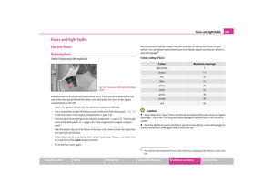 170
170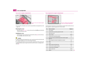 171
171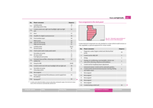 172
172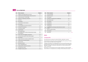 173
173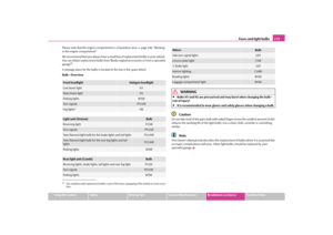 174
174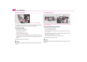 175
175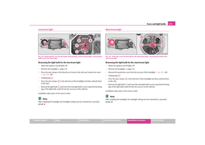 176
176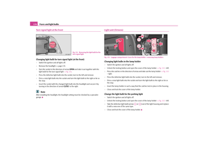 177
177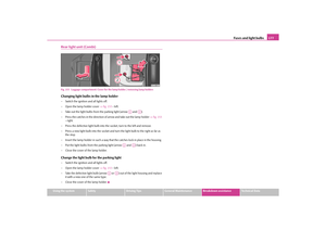 178
178 179
179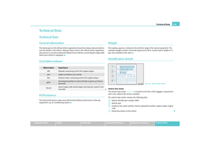 180
180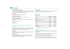 181
181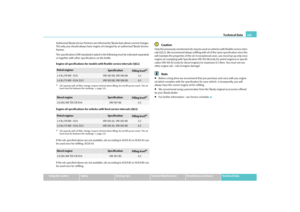 182
182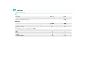 183
183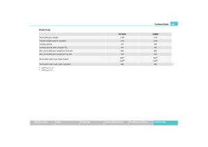 184
184 185
185 186
186 187
187 188
188 189
189 190
190 191
191 192
192 193
193 194
194 195
195 196
196 197
197 198
198 Owners Manual Instruments and Indicator/Warning Lights
22
Warning lightsOverview
The warning lights indicate certain functions or faults.
Fig. 20 Instrument cluster with warning lights
Turn signal lights (to t")