Page 3429 of 3745

PG-46
< SERVICE INFORMATION >
HARNESS
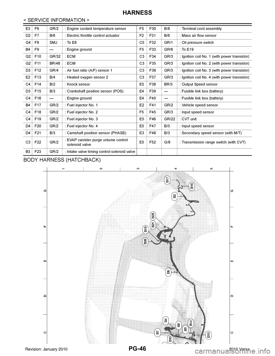
BODY HARNESS (HATCHBACK)
E3 F6 GR/2 : Engine coolant temperature sensor F5 F30 B/8 : Terminal cord assembly
D2 F7 B/6 : Electric throttle control actuatorF2 F31 B/6 : Mass air flow sensor
G4 F8 SMJ : To E8 C5 F32 GR/1 : Oil pressure switch
B4 F9 — : Engine ground F5 F33 GR/6 : To E19
G2 F10 GR/32 : ECM C3 F34 GR/3 : Ignition coil No. 1 (with power transistor)
G2 F11 BR/48 : ECM C3 F35 GR/3 : Ignition coil No. 2 (with power transistor)
D3 F12 GR/4 : Air fuel ratio (A/F) sensor 1 C3 F36 GR/3 : Ignition coil No. 3 (with power transistor)
E2 F13 B/4 : Heated oxygen sensor 2 C3 F37 GR/3 : Ignition coil No. 4 (with power transistor)
C4 F14 B/2 : Knock sensor E5 F38 BR/3 : Output Speed sensor
D3 F15 B/3 : Crankshaft position sensor (POS) E4 F39 — : Fusible link box (battery)
C4 F16 — : Engine ground E4 F40 — : Fusible link box (battery)
B4 F17 GR/2 : Fuel injector No. 1 E2 F41 GR/2 : Vehicle speed sensor
C4 F18 GR/2 : Fuel injector No. 2 F5 F45 GR/3 : Input speed sensor
C4 F19 GR/2 : Fuel injector No. 3E5 F46 GR/22 : CVT unit
D4 F20 GR/2 : Fuel injector No. 4 E5 F47 B/3 : Input speed sensor
D4 F21 B/3 : Camshaft position sensor (PHASE) E3 F48 B/3 : Secondary speed sensor (with M/T)
C3 F22 GR/2 : EVAP canister purge volume control
solenoid valve E5 F52 G/8 : Transmission range switch (with CVT)
B3 F23 GR/2 : Intake valve timing control solenoid valve
Revision: January 20102010 Versa
Page 3434 of 3745
HARNESSPG-51
< SERVICE INFORMATION >
C
DE
F
G H
I
J
L
M A
B
PG
N
O P
A3 B105 B/2 : EVAP canister vent control valve A3 B121 W/32 : Bluetooth control unit
G5 B106 W/4 : To M11 A3 B122 GR/1 : Bluetooth control unit
A2 B107 BR/6 : Rear combination lamp RH D2 B123 B/2 : Rear wheel sensor LH
E4 B108 W/3 : Front door switch RH C3 B124 B/2 : Rear wheel sensor RH
F4 B109 Y/2 : Front RH side air bag module F3 B125 GR/2 : Front console antenna
F4 B110 W/10 : To B300 C3 B126 GR/2 : Rear floor antenna
E5 B111 Y/2 : RH side air bag (satellite) sensor A2 B132 — : Body ground
F4 B112 W/3 : Seat belt buckle switch RH B2 B133 W/2 : To D400
F3 B113 Y/12 : Air bag diagnosis sensor unit A2 B134 W/12 : To D401
E4 B114 — : Body ground A2 B135W/8 : Bluetooth control unit
E4 B115 Y/2 : Front RH seat belt pre-tensioner E5 B138 B/3 : Belt tension sensor
Revision: January 20102010 Versa
Page 3436 of 3745

HARNESSPG-53
< SERVICE INFORMATION >
C
DE
F
G H
I
J
L
M A
B
PG
N
O P
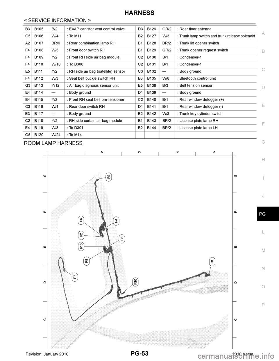
ROOM LAMP HARNESS
B3 B105 B/2 : EVAP canister vent control valve D3 B126 GR/2 : Rear floor antenna
G5 B106 W/4 : To M11 B2 B127 W/3 : Trunk lamp switch and trunk release solenoid
A2 B107 BR/6 : Rear combination lamp RH B1 B128 BR/2 : Trunk lid opener switch
F4 B108 W/3 : Front door switch RH B1 B129 GR/2 : Trunk opener request switch
F4 B109 Y/2 : Front RH side air bag module C2 B130 B/1 : Condenser-1
F4 B110 W/10 : To B300 C2 B131 B/1 : Condenser-1
E5 B111 Y/2 : RH side air bag (satellite) sensor C3 B132 — : Body ground
F4 B112 W/3 : Seat belt buckle switch RH B3 B135 W/8 : Bluetooth control unit
G3 B113 Y/12 : Air bag diagnosis sensor unit E5 B138 B/3 : Belt tension sensor
E4 B114 — : Body ground D1 B139 — : Body ground
E4 B115 Y/2 : Front RH seat belt pre-tensioner C2 B140 B/1 : Rear window defogger (+)
C3 B116 W/1 : Rear door switch RH D1B141 B/1 : Rear window defogger (-)
E3 B117 — : Body ground B2 B142 W/3 : Trunk key cylinder switch
C2 B118 Y/2 : RH side curtain air bag module B1 B143 BR/2 : License plate lamp RH
E4 B119 W/8 : To D301 B2 B144 BR/2 : License plate lamp LH
G5 B120 W/24 : To M14
Revision: January 20102010 Versa
Page 3443 of 3745

PG-60
< SERVICE INFORMATION >
HARNESS
HEATERMTC Heater System
H/LAMP LT Headlamp
H/PHON AV Hands Free Telephone
HORN WW Horn
HO2S2 EC Heated Oxygen Sensor 2
HO2S2H EC Heated Oxygen Sensor 2 Heater
IATS EC Intake Air Temperature Sensor
IGNSYS EC Ignition System
I/KEY BL Intelligent Key System
ILL LT Illumination
INJECT EC Injector
INT/L LT Room/Map, Vanity and Luggage Lamps
IVC EC Intake Valve Timing Control Solenoid Valve
KEYLES BL Remote Keyless Entry System
KS EC Knock Sensor
LPSV AT Line Pressure Solenoid Valve
LPSV CVT Line Pressure Solenoid Valve
L/USSV CVT Lock-up Select Solenoid Valve
MAFS EC Mass Air Flow Sensor
MAIN AT Main Power Supply and Ground Circuit
MAIN EC Main Power Supply and Ground Circuit
METER DI Speedometer, Tachometer, Temp. and Fuel Gauges
MIL/DL EC Malfunction Indicator Lamp
MIRROR GW Door Mirror
NATS BL Nissan Anti-Theft System
NONDTC AT Non-detectable Item
NONDTC CVT Non-detectable Item
ODSW CVT Overdrive Control Switch
OVRCSV AT Over Run Clutch Solenoid Valve
P/SCKT WW Power Socket
PGC/V EC EVAP Canister Purge Volume Control Solenoid Valve
PHASE EC Camshaft Position Sensor (PHASE)
PNP/SW AT Park/Neutral Position Switch
PNP/SW EC Park/Neutral Position Switch
POS EC Crankshaft Position Sensor (POS)
POWER CVT Transmission Control Module (Power Supply)
PRE/SE EC EVAP Control System Pressure Sensor
PRIPS CVT Primary Pressure Sensor
PRSCVT CVT Primary Speed Sensor CVT (Input Speed Sensor)
PT/SEN AT Powertrain Revolution Sensor
RP/SEN EC Refrigerant Pressure Sensor
SECPS CVT Secondary Pressure Sensor
SECPSV CVT Secondary Speed Sensor CVT (Input Speed Sensor)
SEN/PW EC Sensor Power Supply
SESCVT CVT Secondary Pressu re Sensor Solenoid Valve
SHIFT AT A/T Shift Lock System
SHIFT CVT CVT Shift Lock System
SROOF RF Sunroof
SRS SRS Supplemental Restraint System
SSV/A AT Shift Solenoid Valve A
SSV/B AT Shift Solenoid Valve B
START SC Starting System
Revision: January 20102010 Versa
Page 3444 of 3745
HARNESSPG-61
< SERVICE INFORMATION >
C
DE
F
G H
I
J
L
M A
B
PG
N
O P
STM CVT Step Motor
STOP/L LT Stop Lamp
TCV AT Torque Converter Clutch Solenoid Valve
TCV CVT Torque Converter Clutch Solenoid Valve
T/LID BL Trunk Lid Opener
T/WARN WT Low Tire Pressure Warning System
TAIL/L LT Parking, License and Tail Lamps
TPS1 EC Throttle Position Sensor
TPS2 EC Throttle Position Sensor
TPS3 EC Throttle Position Sensor
TR/SW CVT Transmission Range Switch
TURN LT Turn Signal and Hazard Warning Lamps
VDC BRC Vehicle Dynamic Control System
VEHSEC BL Vehicle Security (Theft Warning) System
VENT/V EC EVAP Canister Vent Control Valve
VSSA/T AT Vehicle Speed Sensor A/T (Input Speed Sensor)
VSSMTR AT Vehicle Speed Sensor MTR
WARN DI Warning Lamps
WINDOW GW Power Window
WIP/R WW Rear Wiper and Washer
WIPER WW Front Wiper and Washer
Revision: January 20102010 Versa
Page 3687 of 3745

WT-10
< SERVICE INFORMATION >
TIRE PRESSURE MONITORING SYSTEM
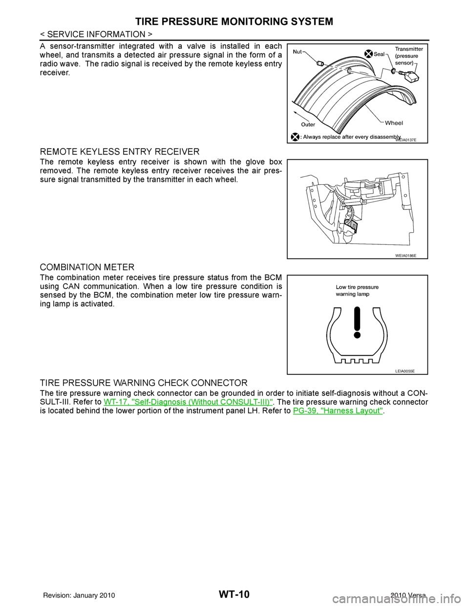
A sensor-transmitter integrated with a valve is installed in each
wheel, and transmits a detected air pressure signal in the form of a
radio wave. The radio signal is received by the remote keyless entry
receiver.
REMOTE KEYLESS ENTRY RECEIVER
The remote keyless entry receiver is shown with the glove box
removed. The remote keyless entry receiver receives the air pres-
sure signal transmitted by the transmitter in each wheel.
COMBINATION METER
The combination meter receives tire pressure status from the BCM
using CAN communication. When a low tire pressure condition is
sensed by the BCM, the combination meter low tire pressure warn-
ing lamp is activated.
TIRE PRESSURE WARNING CHECK CONNECTOR
The tire pressure warning check connector can be grounded in order to initiate self-diagnosis without a CON-
SULT-III. Refer to WT-17, "
Self-Diagnosis (Without CONSULT-III)". The tire pressure warning check connector
is located behind the lower portion of the instrument panel LH. Refer to PG-39, "
Harness Layout".
WEIA0137E
WEIA0186E
LEIA0055E
Revision: January 20102010 Versa
Page 3703 of 3745

WT-26
< SERVICE INFORMATION >
REMOVAL AND INSTALLATION
REMOVAL AND INSTALLATION
Transmitter (Pressure Sensor)INFOID:0000000005397115
REMOVAL
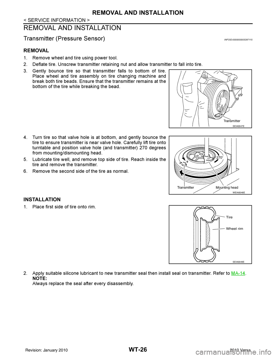
1. Remove wheel and tire using power tool.
2. Deflate tire. Unscrew transmitter retaining nut and allow transmitter to fall into tire.
3. Gently bounce tire so that trans mitter falls to bottom of tire.
Place wheel and tire assembly on tire changing machine and
break both tire beads. Ensure that the transmitter remains at the
bottom of the tire while breaking the bead.
4. Turn tire so that valve hole is at bottom, and gently bounce the tire to ensure transmitter is near valve hole. Carefully lift tire onto
turntable and position valve hole (and transmitter) 270 degrees
from mounting/dismounting head.
5. Lubricate tire well, and remove top side of tire. Reach inside the tire and remove the transmitter.
6. Remove the second side of the tire as normal.
INSTALLATION
1. Place first side of tire onto rim.
2. Apply suitable silicone lubricant to new transmitter seal then install seal on transmitter. Refer to MA-14
.
NOTE:
Always replace the seal after every disassembly.
SEIA0047E
WEIA0046E
SEIA0049E
Revision: January 20102010 Versa
Page 3704 of 3745
REMOVAL AND INSTALLATIONWT-27
< SERVICE INFORMATION >
C
DF
G H
I
J
K L
M A
B
WT
N
O P
3. Mount transmitter on rim and tighten nut. NOTE:
Make sure no burrs exist in the valve stem hole of the wheel.
4. Place wheel on turntable of tire machine. Ensure that transmitter
is 270 degrees from mounting/dismounting head.
NOTE:
Do not touch transmitter with mounting head.
5. Lubricate tire well, and install second side of tire as normal. Ensure that tire does not rotate relative to rim.
6. Inflate tire and balance the wheel and tire assembly. Refer to WT-7, "
Adjustment".
7. Install wheel and tire assembly in appropriate wheel position on vehicle. Refer to WT-7, "
Adjustment".
NOTE:
If replacing the transmitter, t hen transmitter wake up operation
must be performed. Refer to WT-14, "
Transmitter Wake Up Operation".
Transmitter nut : 7.7 N·m (0.79 kg-m, 68 in-lb)
WEIA0137E
WEIA0046E
Revision: January 20102010 Versa