2010 NISSAN TIIDA fuel
[x] Cancel search: fuelPage 1 of 3745

-1
QUICK REFERENCE INDEX
AGENERAL INFORMATIONGIGeneral Information
BENGINEEMEngine Mechanical
LUEngine Lubrication System
COEngine Cooling System
ECEngine Control System
FLFuel System
EXExhaust System
ACCAccelerator Control System
CTRANSMISSION/
TRANSAXLECLClutch System
MTManual Transaxle
ATAutomatic Transaxle
CVTCVT
DDRIVELINE/AXLEFAXFront Axle
RAXRear Axle
ESUSPENSIONFSUFront Suspension
RSURear Suspension
WTRoad Wheels & Tires
FBRAKESBRBrake System
PBParking Brake System
BRCBrake Control System
GSTEERINGPSPower Steering System
STCSteering Control System
HRESTRAINTSSBSeat Belts
SRSSupplemental Restraint System (SRS)
IBODYBLBody, Lock & Security System
GWGlasses, Window System & Mirrors
RFRoof
EIExterior & Interior
IPInstrument Panel
SESeat
JAIR CONDITIONERMTCManual Air Conditioner
KELECTRICALSCStarting & Charging System
LTLighting System
DIDriver Information System
WWWiper, Washer & Horn
BCSBody Control System
LANLAN System
AVAudio Visual, Navigation & Telephone System
ACSAuto Cruise Control System
PGPower Supply, Ground & Circuit Elements
LMAINTENANCEMAMaintenance
Edition: September 2009
Revision: January 2010
Publication No. SM0E-1C11U1
B
D
© 2010 NISSAN NORTH AMERICA, INC.
All rights reserved. No part of this Service Manual may be reproduced or stored in a retrieval system, or transmitted in any
form, or by any means, electronic, mechanical, photo-copying, recording or otherwise, without the prior written permission
of Nissan North America Inc.
A
C
E
F
G
H
I
J
K
L
M
Page 6 of 3745
2010
QUICK REFERENCE CHART: VERSA
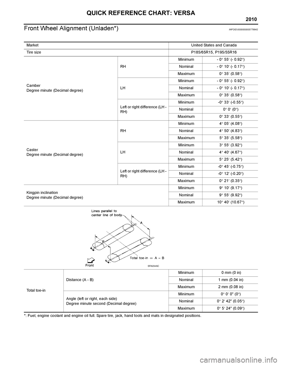
Front Wheel Alignment (Unladen*)
INFOID:0000000005779642
*: Fuel, engine coolant and engine oil full. Spare tire, jack, hand tools and mats in designated positions. Market
United States and Canada
Tire size P185/65R15, P195/55R16
Camber
Degree minute (Decimal degree) RH
Minimum - 0
° 55 ′ (- 0.92 °)
Nominal - 0 ° 10 ′ (- 0.17 °)
Maximum 0 ° 35 ′ (0.58 °)
LH Minimum - 0
° 55 ′ (- 0.92 °)
Nominal - 0 ° 10 ′ (- 0.17 °)
Maximum 0 ° 35 ′ (0.58 °)
Left or right difference (LH -
RH) Minimum -0
° 33 ′ (-0.55 °)
Nominal 0 ° 0 ′ (0 °)
Maximum 0 ° 33 ′ (0.55 °)
Caster
Degree minute (Decimal degree) RH
Minimum 4
° 05 ′ (4.08 °)
Nominal 4 ° 50 ′ (4.83 °)
Maximum 5 ° 35 ′ (5.58 °)
LH Minimum 3
°
55′ (3.92 °)
Nominal 4 ° 40 ′ (4.67 °)
Maximum 5 ° 25 ′ (5.42 °)
Left or right difference (LH -
RH) Minimum -0
° 45 ′ (-0.75 °)
Nominal -0 ° 12 ′ (-0.20 °)
Maximum 0 ° 21 ′ (0.35 °)
Kingpin inclination
Degree minute (Decimal degree) Minimum 9
° 10 ′ (9.17 °)
Nominal 9 ° 55 ′ (9.92 °)
Maximum 10 ° 40 ′ (10.67 °)
Total toe-in Distance (A - B)
Minimum 0 mm (0 in)
Nominal 1 mm (0.04 in)
Maximum 2 mm (0.08 in)
Angle (left or right, each side)
Degree minute second (Decimal degree) Minimum 0
° 0 ′ 0" (0 °)
Nominal 0 ° 2 ′ 42" (0.05 °)
Maximum 0 ° 5 ′ 24" (0.09 °)
SFA234AC
Page 7 of 3745
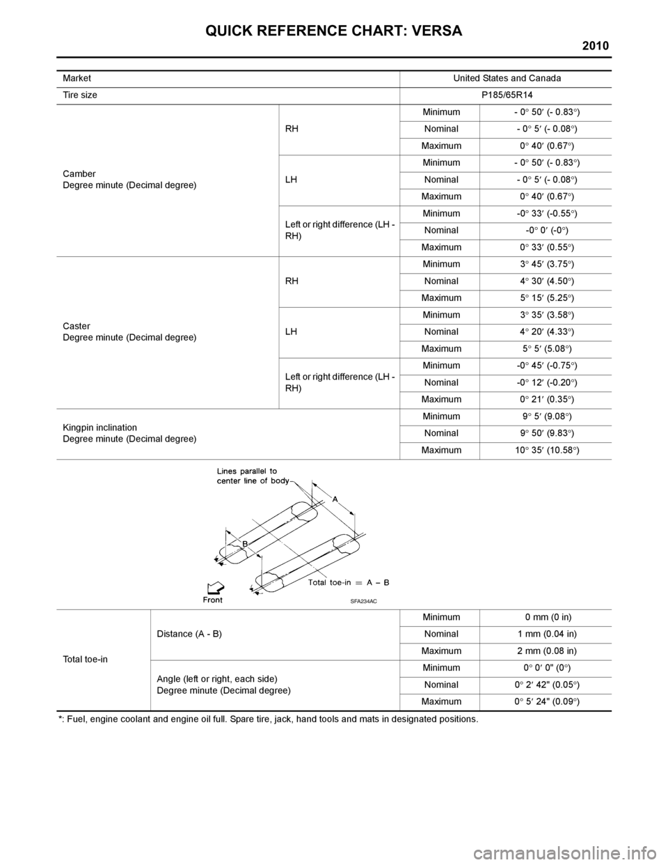
QUICK REFERENCE CHART: VERSA
2010
*: Fuel, engine coolant and engine oil full. Spare tire, jack, hand tools and mats in designated positions.Market
United States and Canada
Tire size P185/65R14
Camber
Degree minute (Decimal degree) RH
Minimum - 0
° 50 ′ (- 0.83 °)
Nominal - 0 ° 5 ′ (- 0.08 °)
Maximum 0 ° 40 ′ (0.67 °)
LH Minimum - 0
° 50 ′ (- 0.83 °)
Nominal - 0 ° 5 ′ (- 0.08 °)
Maximum 0 ° 40 ′ (0.67 °)
Left or right difference (LH -
RH) Minimum -0
° 33 ′ (-0.55 °)
Nominal -0 ° 0 ′ (-0 °)
Maximum 0 ° 33 ′ (0.55 °)
Caster
Degree minute (Decimal degree) RH
Minimum 3
° 45 ′ (3.75 °)
Nominal 4 ° 30 ′ (4.50 °)
Maximum 5 ° 15 ′ (5.25 °)
LH Minimum 3
°
35′ (3.58 °)
Nominal 4 ° 20 ′ (4.33 °)
Maximum 5 ° 5 ′ (5.08 °)
Left or right difference (LH -
RH) Minimum -0
° 45 ′ (-0.75 °)
Nominal -0 ° 12 ′ (-0.20 °)
Maximum 0 ° 21 ′ (0.35 °)
Kingpin inclination
Degree minute (Decimal degree) Minimum 9
° 5 ′ (9.08 °)
Nominal 9 ° 50 ′ (9.83 °)
Maximum 10 ° 35 ′ (10.58 °)
Total toe-in Distance (A - B)
Minimum 0 mm (0 in)
Nominal 1 mm (0.04 in)
Maximum 2 mm (0.08 in)
Angle (left or right, each side)
Degree minute (Decimal degree) Minimum 0
° 0 ′ 0" (0 °)
Nominal 0 ° 2 ′ 42" (0.05 °)
Maximum 0 ° 5 ′ 24" (0.09 °)
SFA234AC
Page 8 of 3745
2010
QUICK REFERENCE CHART: VERSA
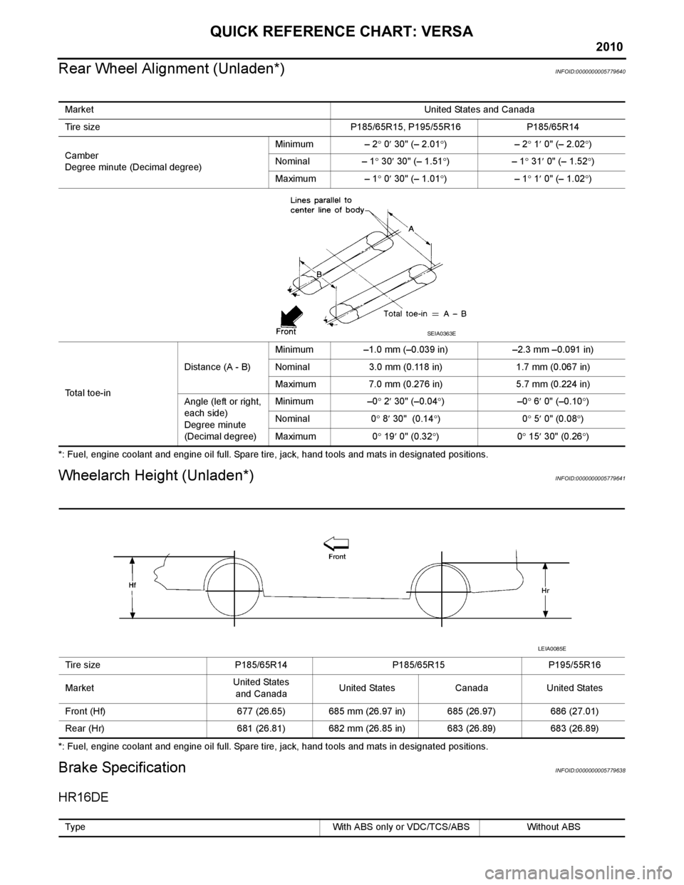
Rear Wheel Alignment (Unladen*)
INFOID:0000000005779640
*: Fuel, engine coolant and engine oil full. Spare tire, jack, hand tools and mats in designated positions.
Wheelarch Height (Unladen*)INFOID:0000000005779641
*: Fuel, engine coolant and engine oil full. Spare tire, jack, hand tools and mats in designated positions.
Brake SpecificationINFOID:0000000005779638
HR16DE
Market United States and Canada
Tire size P185/65R15, P195/55R16 P185/65R14
Camber
Degree minute (Decimal degree) Minimum – 2
° 0 ′ 30" (– 2.01 °)– 2 ° 1 ′ 0" (– 2.02 °)
Nominal – 1 ° 30 ′ 30" (– 1.51 °)– 1 ° 31 ′ 0" (– 1.52 °)
Maximum – 1 ° 0 ′ 30" (– 1.01 °)– 1 ° 1 ′ 0" (– 1.02 °)
Total toe-in Distance (A - B)
Minimum –1.0 mm (–0.039 in) –2.3 mm –0.091 in)
Nominal 3.0 mm (0.118 in) 1.7 mm (0.067 in)
Maximum 7.0 mm (0.276 in) 5.7 mm (0.224 in)
Angle (left or right,
each side)
Degree minute
(Decimal degree) Minimum –0
° 2 ′ 30" (–0.04 °)–0 ° 6 ′ 0" (–0.10 °)
Nominal 0 ° 8 ′ 30" (0.14 °)0 ° 5 ′ 0" (0.08 °)
Maximum 0 ° 19 ′ 0" (0.32 °)0 ° 15 ′ 30" (0.26 °)
SEIA0363E
Tire size P185/65R14 P185/65R15 P195/55R16
Market United States
and Canada United States Canada United States
Front (Hf) 677 (26.65) 685 mm (26.97 in) 685 (26.97) 686 (27.01)
Rear (Hr) 681 (26.81) 682 mm (26.85 in) 683 (26.89) 683 (26.89)
LEIA0085E
Type With ABS only or VDC/TCS/ABS Without ABS
Page 11 of 3745

QUICK REFERENCE CHART: VERSA
2010
Rear Drum BrakeINFOID:0000000005779637
Unit: mm (in)
Unit: mm (in)
Fluids and LubricantsINFOID:0000000005779635
Brake modelLT 2 0
Brake lining Standard thickness (new) 4.0 (0.157)
Repair limit thickness 1.5 (0.059)
Drum Standard inner diameter (new) 203 (7.992)
Repair limit inner diameter 204.5 (8.051)
Brake model
LT 2 3
Brake lining Standard thickness
(new) 4.0 (0.157)
Repair limit thickness 1.5 (0.059)
Drum Standard inner diameter (new) 228.6 (9.000)
Repair limit inner diameter 230.0 (9.055)
Description Capacity (Approximate)
Liter US measure Imp measure
Fuel 50.0 13 1/4 gal 11 gal
Engine oil
Drain and refill With oil filter
change
HR16DE 3.0 3 1/8 qt 2 5/8 qt
MR18DE 4.1 4 3/8 qt 3 5/8 qt
Without oil filter
change HR16DE 2.8 3 qt 2 1/2 qt
MR18DE 3.9 4 1/8 qt 3 3/8 qt
Dry engine (engine overhaul) HR16DE 3.5 3 3/4 qt 3 1/8 qt
MR18DE 4.9 5 1/8 qt 4 3/8 qt
Cooling system
(with reservoir at max level) HR16DE 6.3 6 5/8 qt 5 1/2 qt
MR18DE 6.8 7 1/4 qt 6 qt
Manual transaxle fluid (MTF) 5MT 2.6 5 1/2 pt 4 5/8 pt
6MT 2.0 4 1/4 pt 3 1/2 pt
Automatic transaxle fluid (ATF) HR16DE 7.7 8 1/8 qt 6 3/4 qt
MR18DE 7.9 8 3/8 qt 7 qt
CVT fluid RE0F08B 7.4 7 7/8 qt 6 1/2 qt
Brake and clutch fluid — — —
Multi-purpose grease — — —
Windshield washer fluid 4.5 4 3/4 qt 4 qt
Air conditioning system refrigerant 0.45 ± 0.05 kg 0.99 ± 0.11 lb 0.99 ± 0.11 lb
Air conditioning system oil MR18DE Type 1
and HR16DE
120 m
4.1 fl oz 4.2 fl oz
MR18DE Type 2 100 m3.4 fl oz 3.5 fl oz
Page 50 of 3745
A/T CONTROL SYSTEMAT-33
< SERVICE INFORMATION >
DE
F
G H
I
J
K L
M A
B
AT
N
O P
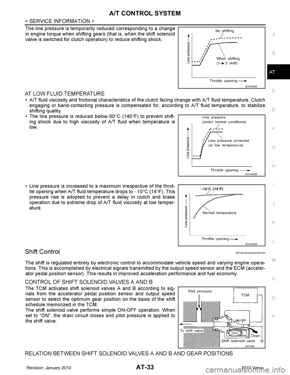
The line pressure is temporarily reduced corresponding to a change
in engine torque when shifting gears (that is, when the shift solenoid
valve is switched for clutch operation) to reduce shifting shock.
AT LOW FLUID TEMPERATURE
• A/T fluid viscosity and frictional characteristics of t he clutch facing change with A/T fluid temperature. Clutch
engaging or band-contacting pressure is compensated for, according to A/T fluid temperature, to stabilize
shifting quality.
• The line pressure is reduced below 60 °C (140° F) to prevent shift-
ing shock due to high viscosity of A/T fluid when temperature is
low.
• Line pressure is increased to a maximum irrespective of the throt- tle opening when A/T fluid temperature drops to −10° C (14° F). This
pressure rise is adopted to prevent a delay in clutch and brake
operation due to extreme drop of A/T fluid viscosity at low temper-
ature.
Shift ControlINFOID:0000000005397225
The shift is regulated entirely by electronic cont rol to accommodate vehicle speed and varying engine opera-
tions. This is accomplished by electrical signals trans mitted by the output speed sensor and the ECM (acceler-
ator pedal position sensor). This results in improved acceleration performance and fuel economy.
CONTROL OF SHIFT SOLENOID VALVES A AND B
The TCM activates shift solenoid valves A and B according to sig-
nals from the accelerator pedal position sensor and output speed
sensor to select the optimum gear position on the basis of the shift
schedule memorized in the TCM.
The shift solenoid valve performs simple ON-OFF operation. When
set to “ON”, the drain circuit closes and pilot pressure is applied to
the shift valve.
RELATION BETWEEN SHIFT SOLENOID VALVES A AND B AND GEAR POSITIONS
SCIA4828E
SCIA4829E
SCIA4830E
SAT008J
Revision: January 20102010 Versa
Page 56 of 3745
ON BOARD DIAGNOSTIC (OBD) SYSTEMAT-39
< SERVICE INFORMATION >
DE
F
G H
I
J
K L
M A
B
AT
N
O P
ON BOARD DIAGNOSTIC (OBD) SYSTEM
IntroductionINFOID:0000000005397230
A/T system has two self-diagnostic systems.
The first is emission-related on board diagnostic system (OBD-II) performed by the TCM in combination with
the ECM. The malfunction is indicated by the MIL (malf unction indicator lamp) and is stored as a DTC in the
ECM memory but not the TCM memory.
The second is the TCM original self-diagnosis indicated by the OD OFF indicator lamp. The malfunction is
stored in the TCM memory. The detected items are ov erlapped with OBD-II self-diagnostic items. For detail,
refer to AT-77, "
CONSULT-III Function (TRANSMISSION)" .
OBD-II Function for A/T SystemINFOID:0000000005397231
The ECM provides emission-related on board diagnostic (O BD-II) functions for the A/T system. One function
is to receive a signal from the TCM used with OBD-rela ted parts of the A/T system. The signal is sent to the
ECM when a malfunction occurs in the corresponding OBD-re lated part. The other function is to indicate a
diagnostic result by means of the MIL (malfunction indica tor lamp) on the instrument panel. Sensors, switches
and solenoid valves are used as sensing elements.
The MIL automatically illuminates in One or Two Trip Detection Logic when a malfunction is sensed in relation
to A/T system parts.
One or Two Trip Detection Logic of OBD-IIINFOID:0000000005397232
ONE TRIP DETECTION LOGIC
If a malfunction is sensed during the first test drive, the MIL will illuminate and the malfunction will be stored in
the ECM memory as a DTC. The TCM is not provided with such a memory function.
TWO TRIP DETECTION LOGIC
When a malfunction is sensed during the first test drive, it is stored in the ECM memory as a 1st trip DTC
(diagnostic trouble code) or 1st trip freeze frame data. At this point, the MIL will not illuminate. — 1st trip
If the same malfunction as that experienced during the fi rst test drive is sensed during the second test drive,
the MIL will illuminate. — 2nd trip
The “trip” in the “One or Two Trip Detection Logic” m eans a driving mode in which self-diagnosis is performed
during vehicle operation.
OBD-II Diagnostic Trouble Code (DTC)INFOID:0000000005397233
HOW TO READ DTC AND 1ST TRIP DTC
DTC and 1st trip DTC can be read by the following methods.
( with CONSULT-III or GST) CONSULT-III or GST (Generic Scan Tool) Examples: P0705, P0720 etc.
These DTC are prescribed by SAE J2012.
(CONSULT-III also displays the malfunctioning component or system.)
• 1st trip DTC No. is the same as DTC No.
• Output of the diagnostic trouble code indicates that the indicated circuit has a malfunction. How-
ever, in case of the Mode II and GST, they do not indicate whether the malfunction is still occurring or
occurred in the past and returned to normal.
CONSULT-III can identify them as shown below, therefore, CONS ULT-III (if available) is recom-
mended.
DTC or 1st trip DTC of a malfunction is displayed in SELF-DIAGNOSTIC RESULTS mode for “ENGINE” with
CONSULT-III. Time data indicates how many times the vehicle was driven after the last detection of a DTC.
If the DTC is being detected curr ently, the time data will be “0”.
If a 1st trip DTC is stored in the ECM, the time data will be “1t”.
Freeze Frame Data and 1st Trip Freeze Frame Data
The ECM has a memory function, which stores the driv ing condition such as fuel system status, calculated
load value, engine coolant temperature, short term f uel trim, long term fuel trim, engine speed and vehicle
speed at the moment the ECM detects a malfunction.
Revision: January 20102010 Versa
Page 57 of 3745
AT-40
< SERVICE INFORMATION >
ON BOARD DIAGNOSTIC (OBD) SYSTEM
Data which are stored in the ECM memory, along with the 1st trip DTC, are called 1st trip freeze frame data,
and the data, stored together with the DTC data, are called freeze frame data and displayed on CONSULT-III
or GST. The 1st trip freeze frame data can only be disp layed on the CONSULT-III screen, not on the GST. For
detail, refer to EC-98, "
CONSULT-III Function" (HR16DE), EC-612, "CONSULT-III Function (ENGINE)"
(MR18DE).
Only one set of freeze frame data (either 1st trip freeze frame data of freeze frame data) can be stored in the
ECM. 1st trip freeze frame data is stored in the ECM memory along with the 1st trip DTC. There is no priority
for 1st trip freeze frame data and it is updated each time a different 1st trip DTC is detected. However, once
freeze frame data (2nd trip detection/MIL on) is stored in the ECM memory, 1st trip freeze frame data is no
longer stored. Remember, only one set of freeze frame data can be stored in the ECM. The ECM has the fol-
lowing priorities to update the data.
Both 1st trip freeze frame data and freeze frame dat a (along with the DTC) are cleared when the ECM mem-
ory is erased.
HOW TO ERASE DTC
The diagnostic trouble code can be erased by CONSULT- III, GST or ECM DIAGNOSTIC TEST MODE as
described following.
• If the battery cable is disconnected, the diagnosti c trouble code will be cleared within 24 hours.
• When you erase the DTC, using CONSULT-III or GS T is easier and quicker than switching the mode
selector on the ECM.
The following emission-related diagnostic information is cleared from the ECM memory when erasing DTC
related to OBD-II. For details, refer to EC-84, "
Diagnosis Description" (HR16DE), EC-542, "Emission-related
Diagnostic Information" (MR18DE).
• Diagnostic trouble codes (DTC)
• 1st trip diagnostic trou ble codes (1st trip DTC)
• Freeze frame data
• 1st trip freeze frame data
• System readiness test (SRT) codes
• Test values
HOW TO ERASE DTC (WITH CONSULT-III)
•If a DTC is displayed for both ECM and TCM, it is necessary to be erased for both ECM and TCM.
1. If the ignition switch stays ON after repair work, be sure to turn ignition switch OFF once. Wait at least 10 seconds and then turn it ON (engine stopped) again.
2. Turn CONSULT-III “ON” and touch “TRANSMISSION”.
3. Touch “SELF-DIAG RESULTS”.
4. Touch “ERASE”. (The DTC in the TCM will be erased.) Then touch “BACK” twice.
5. Touch “ENGINE”.
6. Touch “SELF-DIAG RESULTS”.
7. Touch “ERASE”. (The DTC in the ECM will be erased.)
HOW TO ERASE DTC (WITH GST)
1. If the ignition switch stays ON after repair work, be sure to turn ignition switch OFF once. Wait at least 10 seconds and then turn it ON (engine stopped) again.
2. Perform “TCM SELF-DIAGNOSTIC PROCEDURE (No Tools)”. Refer to AT-82, "
Diagnosis Procedure
without CONSULT-III". (The engine warm-up step can be skipped when performing the diagnosis only\
to
erase the DTC.)
3. Select Mode 4 with Generic Scan Tool (GST). For details, refer to EC-104, "
DiagnosisToolFunction"
(HR16DE), EC-618, "Generic Scan Tool (GST) Function" (MR18DE).
HOW TO ERASE DTC (NO TOOLS)
Priority Items
1 Freeze frame data Misfire — DTC: P0300 - P0306
Fuel Injection System Function — DTC: P0171, P0172, P0174, P0175
2 Except the above items (Includes A/T related items)
3 1st trip freeze frame data
Revision: January 20102010 Versa