2010 NISSAN TIIDA turn signal bulb
[x] Cancel search: turn signal bulbPage 663 of 3745
BL-154
< SERVICE INFORMATION >
INTELLIGENT KEY SYSTEM
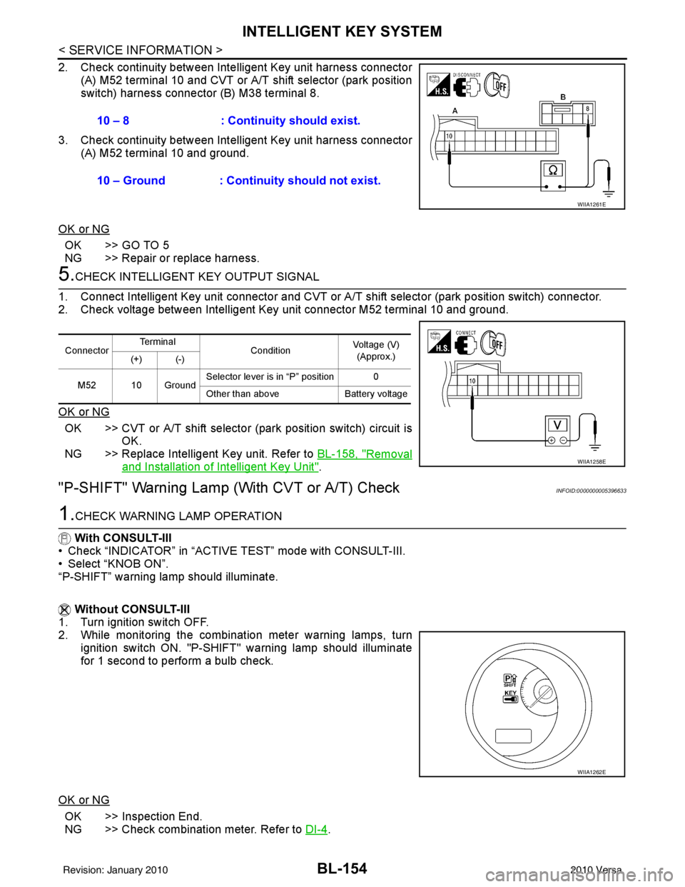
2. Check continuity between Intelligent Key unit harness connector
(A) M52 terminal 10 and CVT or A/T shift selector (park position
switch) harness connector (B) M38 terminal 8.
3. Check continuity between Inte lligent Key unit harness connector
(A) M52 terminal 10 and ground.
OK or NG
OK >> GO TO 5
NG >> Repair or replace harness.
5.CHECK INTELLIGENT KEY OUTPUT SIGNAL
1. Connect Intelligent Key unit connector and CVT or A/T shift selector (park position switch) connector.
2. Check voltage between Intelligent Key unit connector M52 terminal 10 and ground.
OK or NG
OK >> CVT or A/T shift selector (park position switch) circuit is
OK.
NG >> Replace Intelligent Key unit. Refer to BL-158, "
Removal
and Installation of Intelligent Key Unit".
"P-SHIFT" Warning Lamp (With CVT or A/T) CheckINFOID:0000000005396633
1.CHECK WARNING LAMP OPERATION
With CONSULT-III
• Check “INDICATOR” in “ACTIVE TEST” mode with CONSULT-III.
• Select “KNOB ON”.
“P-SHIFT” warning lamp should illuminate.
Without CONSULT-III
1. Turn ignition switch OFF.
2. While monitoring the combination meter warning lamps, turn
ignition switch ON. "P-SHIFT" warning lamp should illuminate
for 1 second to perform a bulb check.
OK or NG
OK >> Inspection End.
NG >> Check combination meter. Refer to DI-4
.
10 – 8 : Continuity should exist.
10 – Ground : Continuity should not exist.
WIIA1261E
Connector
Te r m i n a l
ConditionVoltage (V)
(Approx.)
(+) (-)
M52 10 Ground Selector lever is in “P” position 0
Other than above
Battery voltage
WIIA1258E
WIIA1262E
Revision: January 20102010 Versa
Page 2996 of 3745

LT-1
ELECTRICAL
C
DE
F
G H
I
J
L
M
SECTION LT
A
B
LT
N
O P
CONTENTS
LIGHTING SYSTEM
SERVICE INFORMATION .. ..........................3
PRECAUTIONS .............................................. .....3
Precaution for Supplemental Restraint System
(SRS) "AIR BAG" and "SEAT BELT PRE-TEN-
SIONER" ............................................................. ......
3
Precaution Necessary for Steering Wheel Rota-
tion After Battery Disconnect ............................... ......
3
PREPARATION ...................................................5
Special Service Tool ........................................... ......5
HEADLAMP (FOR USA) .....................................6
Component Parts and Harness Connector Loca-
tion ...................................................................... ......
6
System Description ...................................................6
CAN COMMUNICATION SYSTEM DESCRIP-
TION .................................................................... ......
7
Schematic .................................................................8
Wiring Diagram .........................................................9
Terminal and Reference Value for BCM .................12
Terminal and Reference Value for IPDM E/R .........12
How to Perform Trouble Diagnosis .........................13
Preliminary Check ...................................................13
CONSULT-III Function (BCM) .................................13
CONSULT-III Function (IPDM E/R) .........................14
Headlamp High Beam Does Not Illuminate (Both
Sides) .................................................................. ....
16
Headlamp High Beam Does Not Illuminate (One
Side) .................................................................... ....
18
High Beam Indicator Lamp Does Not Illuminate .....19
Headlamp Low Beam Does Not Illuminate (Both
Sides) .................................................................. ....
20
Headlamp Low Beam Does Not Illuminate (One
Side) .................................................................... ....
22
Headlamps Do Not Turn OFF .................................23
Aiming Adjustment ..................................................24
Bulb Replacement ...................................................25
Removal and Installation .........................................26
Disassembly and Assembly ................................ ....26
HEADLAMP (FOR CANADA) - DAYTIME
LIGHT SYSTEM - ..............................................
28
Component Parts and Harness Connector Loca-
tion ....................................................................... ....
28
System Description ..................................................28
CAN Communication System Description ...............30
Schematic ................................................................31
Wiring Diagram - DTRL - .........................................32
Terminal and Reference Value for BCM ..................35
Terminal and Reference Value for IPDM E/R ...... ....35
How to Perform Trouble Diagnosis ..........................36
Preliminary Check ...................................................36
CONSULT-III Function (BCM) .................................36
CONSULT-III Function (IPDM E/R) ..................... ....36
Daytime Light Control Does Not Operate Properly
(High Beam Headlamps Operate Properly) .............
36
Aiming Adjustment ...................................................38
Bulb Replacement ...................................................39
Removal and Installation .........................................40
Disassembly and Assembly .....................................40
FRONT FOG LAMP ..........................................42
Component Parts and Harness Connector Loca-
tion ...........................................................................
42
System Description ..................................................42
CAN Communication System Description ...............43
Wiring Diagram - F/FOG - .......................................44
Terminal and Reference Value for BCM ..................45
Terminal and Reference Value for IPDM E/R ...... ....45
How to Proceed with Trouble Diagnosis ..................46
Preliminary Check ............................................... ....46
CONSULT-III Function (BCM) .................................46
CONSULT-III Function (IPDM E/R) ..................... ....46
Front Fog lamps Do Not Illuminate (Both Sides) .....46
Front Fog Lamp Does Not Illuminate (One Side) ....48
Aiming Adjustment ...................................................49
Bulb Replacement ...................................................50
Removal and Installation .........................................50
TURN SIGNAL AND HAZARD WARNING
LAMPS ..............................................................
51
Revision: January 20102010 Versa
Page 2997 of 3745

LT-2
Component Parts and Harness Connector Loca-
tion ..........................................................................
51
System Description .................................................51
CAN Communication System Description ..............53
Schematic ............................................................ ...54
Wiring Diagram - TURN - ........................................55
Terminal and Reference Value for BCM .................58
How to Proceed with Trouble Diagnosis .................58
Preliminary Check ..................................................59
CONSULT-III Function (BCM) ................................59
Turn Signals Do Not Operate .................................59
Front Turn Signal Lamp Does Not Operate ............59
Rear Turn Signal Lamp Does Not Operate ............60
Hazard Warning Lamp Does Not Operate But
Turn Signal Lamp Operates ...................................
61
Turn Signal Indicator Lamp Does Not Operate ......62
Bulb Replacement for Front Turn Signal Lamp ......62
Bulb Replacement for Rear Turn Signal Lamp .......62
Removal and Installation of Front Turn Signal
Lamp .......................................................................
62
Removal and Installation of Rear Turn Signal
Lamp .......................................................................
62
LIGHTING AND TURN SIGNAL SWITCH .........63
Removal and Installation ..................................... ...63
HAZARD SWITCH .............................................64
Removal and Installation ..................................... ...64
COMBINATION SWITCH ..................................65
Wiring Diagram - COMBSW - .............................. ...65
Combination Switch Reading Function ...................65
Terminal and Reference Value for BCM .................66
CONSULT-III Function (BCM) ................................66
Combination Switch Inspection ..............................66
Removal and Installation ..................................... ...68
STOP LAMP ......................................................69
Wiring Diagram - STOP/L .................................... ...69
Wiring Diagram - STOP/L .......................................70
Bulb Replacement for High-Mounted Stop Lamp ...70
Bulb Replacement for Rear Combination Lamp for
Stop Lamp ..............................................................
71
Removal and Installation of High-Mounted Stop
Lamp .......................................................................
71
Removal and Installation of Rear Combination
Lamp for Stop Lamp ...............................................
72
BACK-UP LAMP ................................................73
Wiring Diagram - BACK/L - .................................. ...73
Bulb Replacement ..................................................73
Removal and Installation ........................................74
PARKING, LICENSE PLATE AND TAIL
LAMPS ...............................................................
75
Component Parts and Harness Connector Loca-
tion ....................................................................... ...
75
System Description .............................................. ...75
CAN Communication System Description ..............76
Schematic ...............................................................77
Wiring Diagram - TAIL/L - .......................................78
Terminal and Reference Value for BCM .............. ...81
Terminal and Reference Value for IPDM E/R .........81
How to Proceed with Trouble Diagnosis .................82
Preliminary Check ...................................................82
CONSULT-III Function (BCM) ............................. ...82
CONSULT-III Function (IPDM E/R) ........................82
Parking, License Plate and Tail Lamps Do Not Il-
luminate ..................................................................
82
Parking, License Plate and Tail Lamps Do Not
Turn OFF (After Approx. 10 Minutes) .....................
85
Bulb Replacement ................................................ ...85
Removal and Installation .........................................86
REAR COMBINATION LAMP ........................ ...88
Component .......................................................... ...88
Bulb Replacement ...................................................88
Removal and Installation .........................................89
Disassembly and Assembly ................................. ...89
INTERIOR LAMP ...............................................91
Map Lamp ............................................................ ...91
Luggage Room Lamp, Hatch Back .........................91
Trunk Room Lamp, Sedan ......................................92
Vanity Mirror Lamp ..................................................92
INTERIOR ROOM LAMP ...................................94
Component Parts and Harness Connector Loca-
tion ....................................................................... ...
94
System Description .................................................94
Schematic ...............................................................98
Wiring Diagram - INT/L - .........................................99
Terminal and Reference Value for BCM ...............103
How to Proceed with Trouble Diagnosis ...............103
Preliminary Check .................................................104
CONSULT-III Function (BCM) ............................. .104
Interior Room Lamp Control Does Not Operate
(With Map Lamp) ..................................................
105
Interior Room Lamp Control Does Not Operate
(Without Map Lamp) .............................................
107
Bulb Replacement .................................................108
Removal and Installation .......................................109
ILLUMINATION .............................................. ..110
System Description .............................................. .110
CAN Communication System Description ............111
Schematic .............................................................112
Wiring Diagram - ILL - ...........................................113
BULB SPECIFICATIONS ............................... ..117
Headlamp ............................................................. .117
Exterior Lamp ........................................................117
Interior Lamp/Illumination ......................................117
Revision: January 20102010 Versa
Page 3012 of 3745
HEADLAMP (FOR USA)LT-17
< SERVICE INFORMATION >
C
DE
F
G H
I
J
L
M A
B
LT
N
O P
Without CONSULT-III
1. Start auto active test. Refer to PG-20, "
Auto Active Test" .
2. Make sure headlamp high beam operates.
OK or NG
OK >> GO TO 3.
NG >> GO TO 4.
3.CHECK IPDM E/R
1. Select “IPDM E/R” on CONSUL T-III. Select “DATA MONITOR” on “SELECT DIAG MODE” screen.
2. Make sure “HL HI REQ” turns ON when lighting switch is in high position.
OK or NG
OK >> Replace IPDM E/R. Refer to PG-28, "Removal and Installation of IPDM E/R" .
NG >> Replace BCM. Refer to BCS-19, "
Removal and Installation of BCM" .
4.HEADLAMP HIGH BEAM FUSE INSPECTION
Inspect 10A fuse No. 34 (RH) and fuse No. 35 (LH).
OK or NG
OK >> GO TO 5.
NG >> Repair harness.
5.BULB INSPECTION
Inspect inoperative headlamp bulbs.
OK or NG
OK >> GO TO 6.
NG >> Replace headlamp bulb. LT-25, "
Bulb Replacement" .
6.CHECK HEADLAMP INPUT SIGNAL
With CONSULT-III
1. Turn ignition switch OFF.
2. Disconnect headlamp connector.
3. Select “IPDM E/R” on CONSUL T-III. Select “ACTIVE TEST” on “SELECT DIAG MODE” screen.
4. Select “EXTERNAL LAMPS” on “SELECT TEST ITEM” screen.
5. Touch “HI” screen.
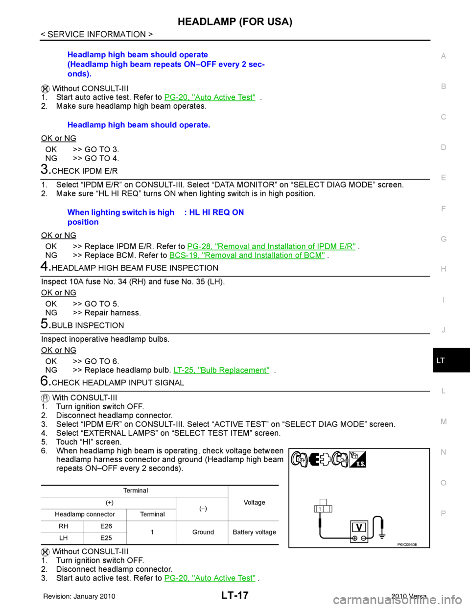
6. When headlamp high beam is operating, check voltage between headlamp harness connector and ground (Headlamp high beam
repeats ON–OFF every 2 seconds).
Without CONSULT-III
1. Turn ignition switch OFF.
2. Disconnect headlamp connector.
3. Start auto active test. Refer to PG-20, "
Auto Active Test" .
Headlamp high beam should operate
(Headlamp high beam repeats ON–OFF every 2 sec-
onds).
Headlamp high beam should operate.
When lighting switch is high
position
: HL HI REQ ON
Te r m i n a l
Vo l ta g e
(+)
(−)
Headlamp connector Terminal
RH E26 1Ground Battery voltage
LH E25
PKIC0960E
Revision: January 20102010 Versa
Page 3014 of 3745
HEADLAMP (FOR USA)LT-19
< SERVICE INFORMATION >
C
DE
F
G H
I
J
L
M A
B
LT
N
O P
3.CHECK HEADLAMP INPUT SIGNAL
1. Turn ignition switch OFF.
2. Disconnect headlamp connector.
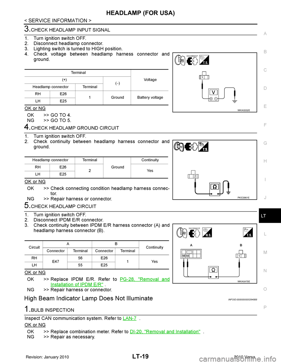
3. Lighting switch is turned to HIGH position.
4. Check voltage between headlamp harness connector and ground.
OK or NG
OK >> GO TO 4.
NG >> GO TO 5.
4.CHECK HEADLAMP GROUND CIRCUIT
1. Turn ignition switch OFF.
2. Check continuity between headlamp harness connector and ground.
OK or NG
OK >> Check connecting condition headlamp harness connec- tor.
NG >> Repair harness or connector.
5.CHECK HEADLAMP CIRCUIT
1. Turn ignition switch OFF.
2. Disconnect IPDM E/R connector.
3. Check continuity between IPDM E/R harness connector (A) and headlamp harness connector (B).
OK or NG
OK >> Replace IPDM E/R. Refer to PG-28, "Removal and
Installation of IPDM E/R" .
NG >> Repair harness or connector.
High Beam Indicator Lamp Does Not IlluminateINFOID:0000000005394888
1.BULB INSPECTION
Inspect CAN communication system. Refer to LAN-7
.
OK or NG
OK >> Replace combination meter. Refer to DI-20, "Removal and Installation" .
NG >> Repair as necessary.
Te r m i n a l
Vo l ta g e
(+)
(−)
Headlamp connector Terminal
RH E26 1Ground Battery voltage
LH E25
WKIA5552E
Headlamp connector Terminal
Ground Continuity
RH E26 2Y es
LH E25
PKIC0961E
Circuit AB
Continuity
Connector Terminal Connector Terminal
RH E47 56 E26
1Yes
LH 55 E25
WKIA5470E
Revision: January 20102010 Versa
Page 3015 of 3745
LT-20
< SERVICE INFORMATION >
HEADLAMP (FOR USA)
Headlamp Low Beam Does Not Illuminate (Both Sides)
INFOID:0000000005394889
1.CHECK COMBINATION SWITCH INPUT SIGNAL
With CONSULT-III
1. Select “BCM” on CONSULT-III. Select “HEAD LAMP” on “SELECT TEST ITEM” screen.
2. Select “DATA MONITOR” on “SELECT DIAG MODE” screen. Make sure that “HEAD LAMP SW 1” and
“HEAD LAMP SW 2” turns ON-OFF linked with operation of lighting switch.
Without CONSULT-III
Refer to LT-66, "
Combination Switch Inspection" .
OK or NG
OK >> GO TO 2.
NG >> Check combination switch (lighting switch). Refer to LT-66, "
Combination Switch Inspection" .
2.CHECK HEADLAMP ACTIVE TEST
With CONSULT-III
1. Select “IPDM E/R” on CONSULT-III. Select “ACTIVE TEST” on “SELECT DIAG MODE” screen.
2. Select “EXTERNAL LAMPS” on “SELECT TEST ITEM” screen.
3. Touch “LO” screen.
4. Make sure headlamp low beam operates.
Without CONSULT-III
1. Start auto active test. Refer to PG-20, "
Auto Active Test" .
2. Make sure headlamp low beam operates.
OK or NG
OK >> GO TO 3.
NG >> GO TO 4.
3.CHECK IPDM E/R
1. Select “IPDM E/R” on CONSULT-III. Select “DATA MONITOR” on “SELECT DIAG MODE” screen.
2. Make sure “HL LO REQ” turns ON when lighting switch is in 2ND position.
OK or NG
OK >> Replace IPDM E/R. Refer to PG-28, "Removal and Installation of IPDM E/R" .
NG >> Replace BCM. Refer to BCS-19, "
Removal and Installation of BCM" .
4.HEADLAMP LOW BEAM FUSE INSPECTION
Inspect 15A fuse No. 40 (LH) and fuse No. 41 (RH).
OK or NG
OK >> GO TO 5.
NG >> Repair harness.
5.BULB INSPECTION
Inspect inoperative headlamp bulbs.
OK or NG
OK >> GO TO 6.
NG >> Replace headlamp bulb. LT-25, "
Bulb Replacement" .
When lighting switch is 2ND
position
: HEAD LAMP SW 1 ON
: HEAD LAMP SW 2 ON
Headlamp low beam should operate.
Headlamp low beam should operate.
When lighting switch is 2ND
position: HL LO REQ ON
Revision: January 20102010 Versa
Page 3017 of 3745
LT-22
< SERVICE INFORMATION >
HEADLAMP (FOR USA)
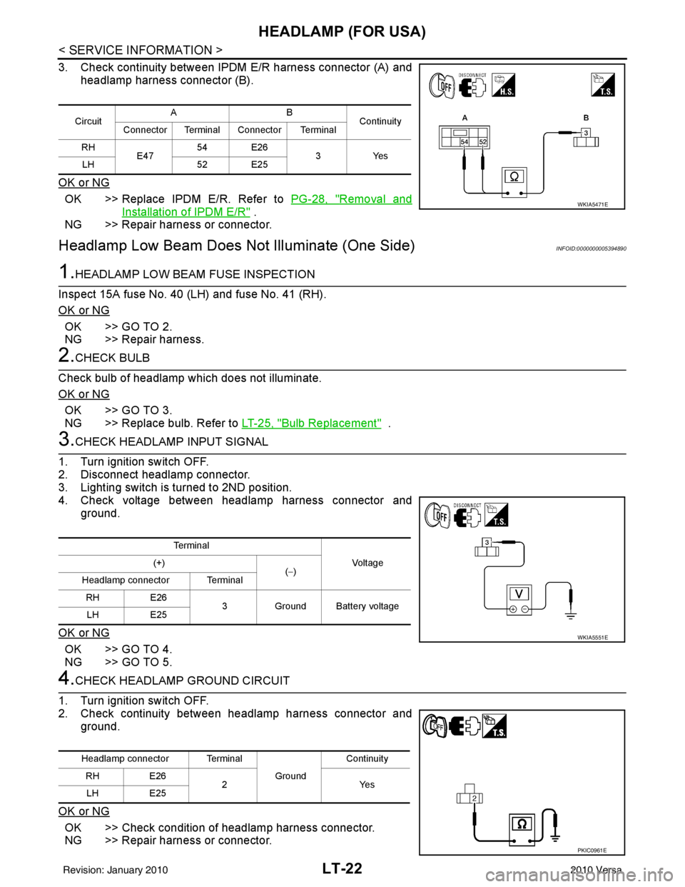
3. Check continuity between IPDM E/R harness connector (A) and
headlamp harness connector (B).
OK or NG
OK >> Replace IPDM E/R. Refer to PG-28, "Removal and
Installation of IPDM E/R" .
NG >> Repair harness or connector.
Headlamp Low Beam Does Not Illuminate (One Side)INFOID:0000000005394890
1.HEADLAMP LOW BEAM FUSE INSPECTION
Inspect 15A fuse No. 40 (LH) and fuse No. 41 (RH).
OK or NG
OK >> GO TO 2.
NG >> Repair harness.
2.CHECK BULB
Check bulb of headlamp which does not illuminate.
OK or NG
OK >> GO TO 3.
NG >> Replace bulb. Refer to LT-25, "
Bulb Replacement" .
3.CHECK HEADLAMP INPUT SIGNAL
1. Turn ignition switch OFF.
2. Disconnect headlamp connector.
3. Lighting switch is turned to 2ND position.
4. Check voltage between headlamp harness connector and ground.
OK or NG
OK >> GO TO 4.
NG >> GO TO 5.
4.CHECK HEADLAMP GROUND CIRCUIT
1. Turn ignition switch OFF.
2. Check continuity between headlamp harness connector and ground.
OK or NG
OK >> Check condition of headlamp harness connector.
NG >> Repair harness or connector.
Circuit AB
Continuity
Connector Terminal Connector Terminal
RH E47 54 E26
3Yes
LH 52 E25
WKIA5471E
Terminal
Vo l ta g e
(+)
(−)
Headlamp connector Terminal
RH E26
3 Ground Battery voltage
LH E25
WKIA5551E
Headlamp connector Terminal
Ground Continuity
RH E26
2Y es
LH E25
PKIC0961E
Revision: January 20102010 Versa
Page 3021 of 3745
LT-26
< SERVICE INFORMATION >
HEADLAMP (FOR USA)
2. Remove the headlamp. Refer to LT-26, "Removal and Installation".
3. Turn bulb socket counterclockwise and unlock it.
4. Remove bulb from its socket.
FRONT TURN SIGNAL LAMP
1. Turn lighting switch OFF.
2. Remove the headlamp. Refer to LT-26, "
Removal and Installation".
3. Turn bulb socket counterclockwise and unlock it.
4. Remove bulb from its socket.
Removal and InstallationINFOID:0000000005394894
REMOVAL
1. Disconnect the negative battery terminal.
2. Remove front bumper fascia. Refer to EI-15
.
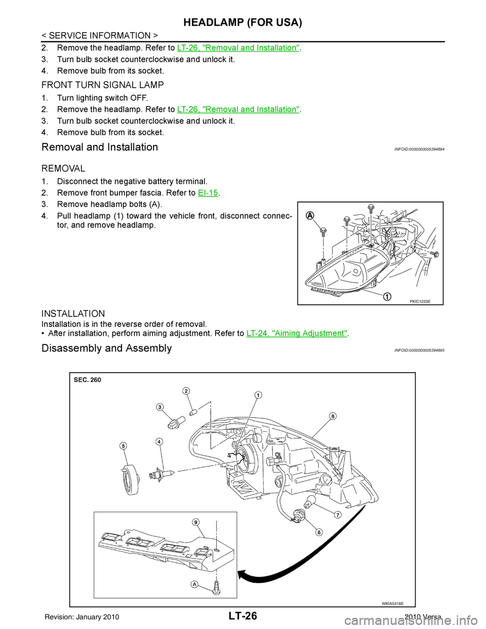
3. Remove headlamp bolts (A).
4. Pull headlamp (1) toward the vehicle front, disconnect connec- tor, and remove headlamp.
INSTALLATION
Installation is in the reverse order of removal.
• After installation, perform aiming adjustment. Refer to LT-24, "
Aiming Adjustment".
Disassembly and AssemblyINFOID:0000000005394895
PKIC1223E
WKIA5418E
Revision: January 20102010 Versa