2010 NISSAN TIIDA valve
[x] Cancel search: valvePage 3292 of 3745
PREPARATIONMTC-13
< SERVICE INFORMATION >
C
DE
F
G H
I
K L
M A
B
MTC
N
O P
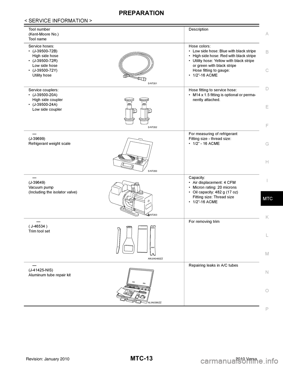
Service hoses:
• (J-39500-72B) High side hose
• (J-39500-72R) Low side hose
• (J-39500-72Y)
Utility hose Hose colors:
• Low side hose: Blue with black stripe
• High side hose: Red with black stripe
• Utility hose: Yellow with black stripe
or green with black stripe
Hose fitting to gauge:
• 1/2”-16 ACME
Service couplers:
• (J-39500-20A) High side coupler
• (J-39500-24A)
Low side coupler Hose fitting to service hose:
• M14 x 1.5 fitting is optional or perma-
nently attached.
—
(J-39699)
Refrigerant weight scale For measuring of refrigerant
Fitting size - thread size:
• 1/2” - 16 ACME
—
(J-39649)
Va c u u m p u m p
(Including the isolator valve) Capacity:
• Air displacement: 4 CFM
• Micron rating: 20 microns
• Oil capacity: 482 g (17 oz)
Fitting size: Thread size
• 1/2”-16 ACME
—
( J-46534 )
Trim tool set For removing trim
—
(J-41425-NIS)
Aluminum tube repair kit Repairing leaks in A/C tubes
Tool number
(Kent-Moore No.)
Tool name
Description
S-NT201
S-NT202
S-NT200
S-NT203
AWJIA0483ZZ
ALIIA0390ZZ
Revision: January 20102010 Versa
Page 3294 of 3745
REFRIGERATION SYSTEMMTC-15
< SERVICE INFORMATION >
C
DE
F
G H
I
K L
M A
B
MTC
N
O P
REFRIGERATION SYSTEM
Refrigerant CycleINFOID:0000000005396484
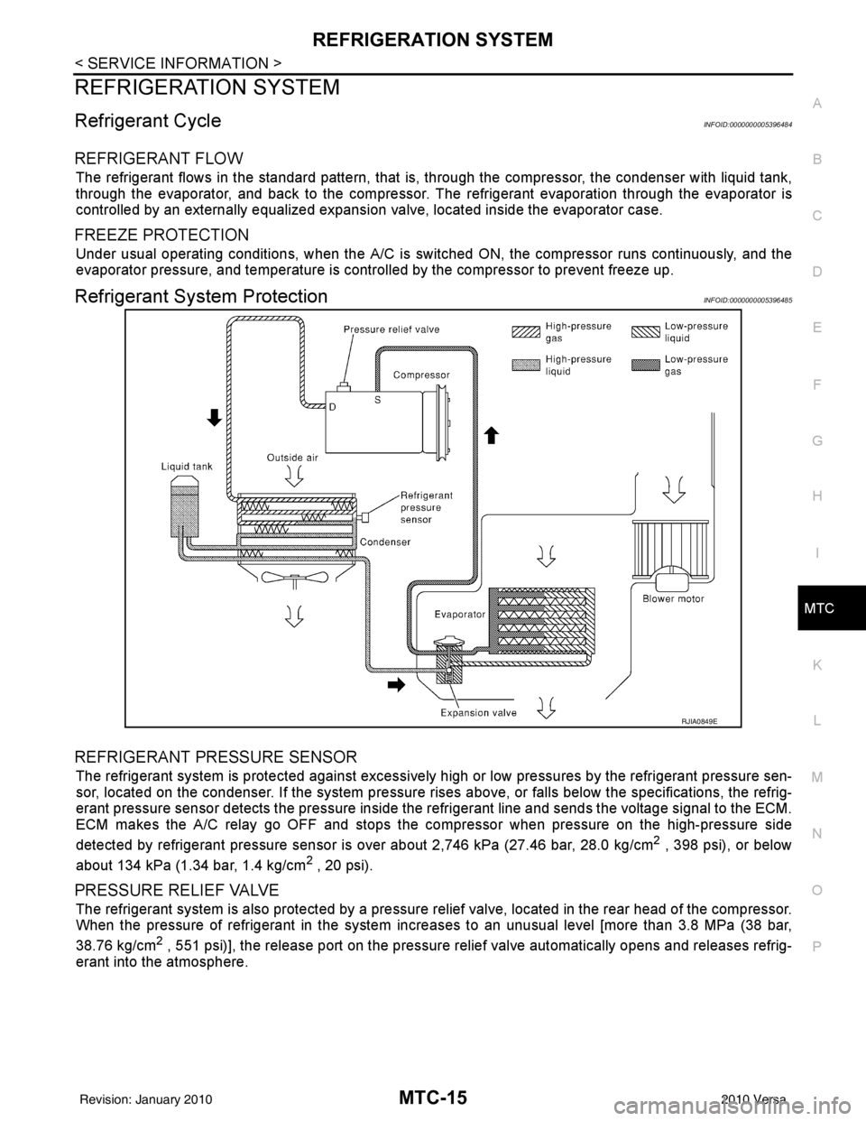
REFRIGERANT FLOW
The refrigerant flows in the standard pattern, that is, through the compressor, the condenser with liquid tank,
through the evaporator, and back to the compressor. T he refrigerant evaporation through the evaporator is
controlled by an externally equalized expansion valve, located inside the evaporator case.
FREEZE PROTECTION
Under usual operating conditions, when the A/C is s witched ON, the compressor runs continuously, and the
evaporator pressure, and temperature is controlled by the compressor to prevent freeze up.
Refrigerant System ProtectionINFOID:0000000005396485
REFRIGERANT PRESSURE SENSOR
The refrigerant system is protected against excessively hi gh or low pressures by the refrigerant pressure sen-
sor, located on the condenser. If the system pressure rises above, or falls below the specifications, the refrig-
erant pressure sensor detects the pressure inside t he refrigerant line and sends the voltage signal to the ECM.
ECM makes the A/C relay go OFF and stops the compressor when pressure on the high-pressure side
detected by refrigerant pressure sensor is over about 2,746 kPa (27.46 bar, 28.0 kg/cm
2 , 398 psi), or below
about 134 kPa (1.34 bar, 1.4 kg/cm
2 , 20 psi).
PRESSURE RELIEF VALVE
The refrigerant system is also protected by a pressure relief valve, located in the rear head of the compressor.
When the pressure of refrigerant in the system in creases to an unusual level [more than 3.8 MPa (38 bar,
38.76 kg/cm
2 , 551 psi)], the release port on the pressure relief valve automatically opens and releases refrig-
erant into the atmosphere.
RJIA0849E
Revision: January 20102010 Versa
Page 3330 of 3745
TROUBLE DIAGNOSISMTC-51
< SERVICE INFORMATION >
C
DE
F
G H
I
K L
M A
B
MTC
N
O P
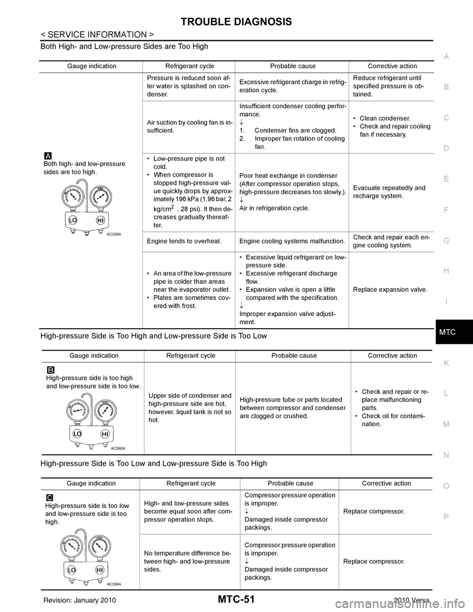
Both High- and Low-pressure Sides are Too High
High-pressure Side is Too High and Low-pressure Side is Too Low
High-pressure Side is Too Low and Low-pressure Side is Too High
Gauge indication
Refrigerant cycle Probable causeCorrective action
Both high- and low-pressure
sides are too high. Pressure is reduced soon af-
ter water is splashed on con-
denser.
Excessive refrigerant charge in refrig-
eration cycle. Reduce refrigerant until
specified pressure is ob-
tained.
Air suction by cooling fan is in-
sufficient. Insufficient condenser cooling perfor-
mance.
↓
1. Condenser fins are clogged.
2. Improper fan rotation of cooling
fan. • Clean condenser.
• Check and repair cooling
fan if necessary.
• Low-pressure pipe is not cold.
• When compressor is
stopped high-pressure val-
ue quickly drops by approx-
imately 196 kPa (1.96 bar, 2
kg/cm
2 , 28 psi). It then de-
creases gradually thereaf-
ter. Poor heat exchange in condenser
(After compressor operation stops,
high-pressure decreases too slowly.).
↓
Air in refrigeration cycle.
Evacuate repeatedly and
recharge system.
Engine tends to overheat. Engine cooling systems malfunction. Check and repair each en-
gine cooling system.
• An area of the low-pressure pipe is colder than areas
near the evaporator outlet.
• Plates are sometimes cov- ered with frost. • Excessive liquid refrigerant on low-
pressure side.
• Excessive refrigerant discharge flow.
• Expansion valve is open a little
compared with the specification.
↓
Improper expansion valve adjust-
ment. Replace expansion valve.
AC359A
Gauge indication
Refrigerant cycle Probable causeCorrective action
High-pressure side is too high
and low-pressure side is too low. Upper side of condenser and
high-pressure side are hot,
however, liquid tank is not so
hot.High-pressure tube or parts located
between compressor and condenser
are clogged or crushed. • Check and repair or re-
place malfunctioning
parts.
• Check oil for contami- nation.
AC360A
Gauge indication Refrigerant cycle Probable causeCorrective action
High-pressure side is too low
and low-pressure side is too
high. High- and low-pressure sides
become equal soon after com-
pressor operation stops. Compressor pressure operation
is improper.
↓
Damaged inside compressor
packings.
Replace compressor.
No temperature difference be-
tween high- and low-pressure
sides. Compressor pressure operation
is improper.
↓
Damaged inside compressor
packings.
Replace compressor.
AC356A
Revision: January 20102010 Versa
Page 3331 of 3745
MTC-52
< SERVICE INFORMATION >
TROUBLE DIAGNOSIS
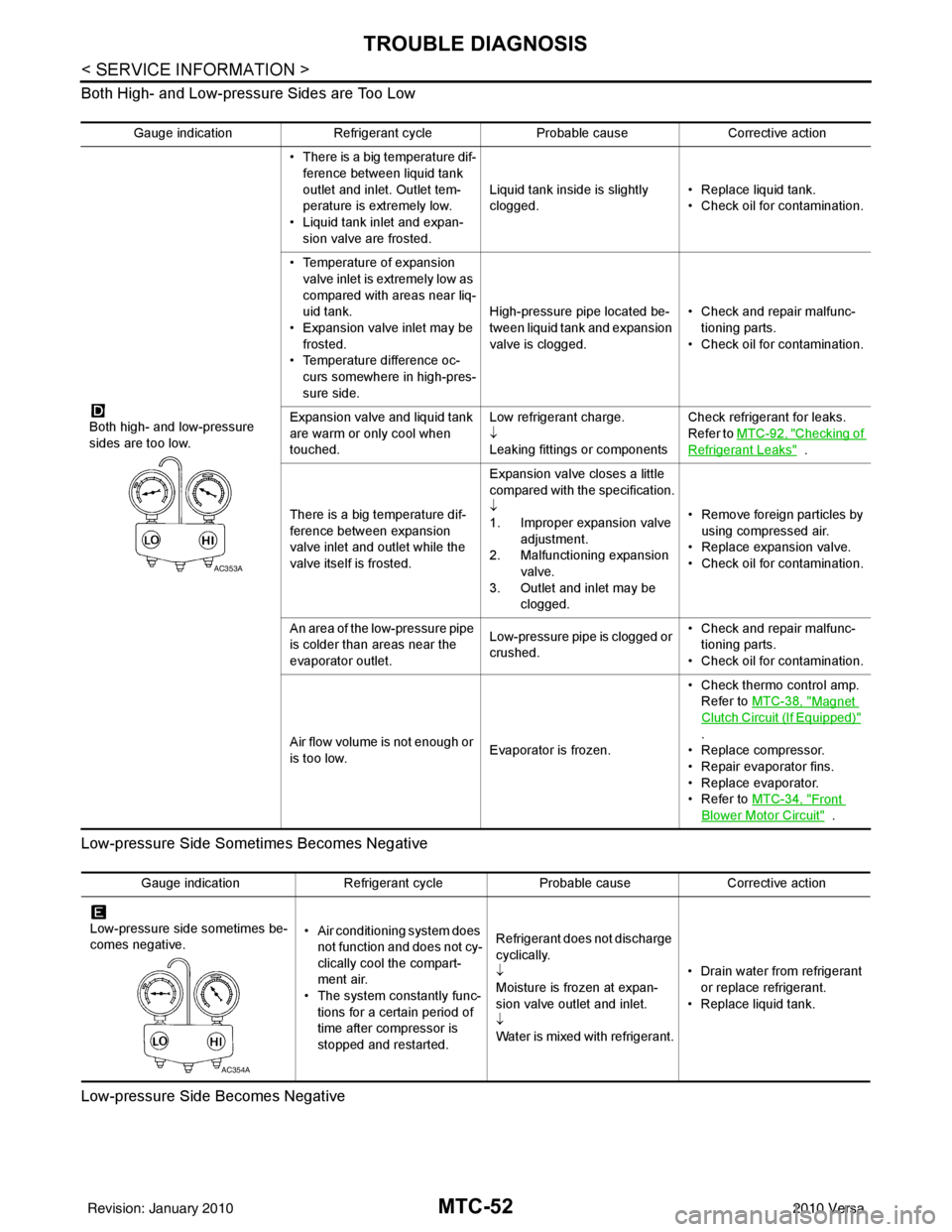
Both High- and Low-pressure Sides are Too Low
Low-pressure Side Sometimes Becomes Negative
Low-pressure Side Becomes Negative
Gauge indication Refrigerant cycle Probable causeCorrective action
Both high- and low-pressure
sides are too low. • There is a big temperature dif-
ference between liquid tank
outlet and inlet. Outlet tem-
perature is extremely low.
• Liquid tank inlet and expan- sion valve are frosted. Liquid tank inside is slightly
clogged.
• Replace liquid tank.
• Check oil for contamination.
• Temperature of expansion valve inlet is extremely low as
compared with areas near liq-
uid tank.
• Expansion valve inlet may be
frosted.
• Temperature difference oc- curs somewhere in high-pres-
sure side. High-pressure pipe located be-
tween liquid tank and expansion
valve is clogged.
• Check and repair malfunc-
tioning parts.
• Check oil for contamination.
Expansion valve and liquid tank
are warm or only cool when
touched. Low refrigerant charge.
↓
Leaking fittings or componentsCheck refrigerant for leaks.
Refer to
MTC-92, "
Checking of
Refrigerant Leaks" .
There is a big temperature dif-
ference between expansion
valve inlet and outlet while the
valve itself is frosted. Expansion valve closes a little
compared with the specification.
↓
1. Improper expansion valve
adjustment.
2. Malfunctioning expansion valve.
3. Outlet and inlet may be clogged. • Remove foreign particles by
using compressed air.
• Replace expansion valve.
• Check oil for contamination.
An area of the low-pressure pipe
is colder than areas near the
evaporator outlet. Low-pressure pipe is clogged or
crushed.• Check and repair malfunc-
tioning parts.
• Check oil for contamination.
Air flow volume is not enough or
is too low. Evaporator is frozen.• Check thermo control amp.
Refer to MTC-38, "
Magnet
Clutch Circuit (If Equipped)"
.
• Replace compressor.
• Repair evaporator fins.
• Replace evaporator.
•Refer to MTC-34, "
Front
Blower Motor Circuit" .
AC353A
Gauge indication Refrigerant cycleProbable causeCorrective action
Low-pressure side sometimes be-
comes negative. • Air conditioning system does
not function and does not cy-
clically cool the compart-
ment air.
• The system constantly func-
tions for a certain period of
time after compressor is
stopped and restarted. Refrigerant does not discharge
cyclically.
↓
Moisture is frozen at expan-
sion valve outlet and inlet.
↓
Water is mixed with refrigerant.
• Drain water from refrigerant
or replace refrigerant.
• Replace liquid tank.
AC354A
Revision: January 20102010 Versa
Page 3332 of 3745
TROUBLE DIAGNOSISMTC-53
< SERVICE INFORMATION >
C
DE
F
G H
I
K L
M A
B
MTC
N
O P
Insufficient HeatingINFOID:0000000005396504
SYMPTOM: Insufficient heating
INSPECTION FLOW
1.CONFIRM SYMPTOM BY PERFORMING OPERAT IONAL CHECK - TEMPERATURE INCREASE
1. Turn temperature control dial clockwise to maximum heat position.
2. Check for hot air at discharge air outlets.
Can the symptom be duplicated?
YES >> GO TO 3.
NO >> GO TO 2.
2.CHECK FOR ANY SYMPTOMS
Perform a complete operational check for any symptoms. Refer to MTC-31, "
Operational Check" .
Does another symptom exist?
YES >> Refer to MTC-23, "How to Perform Trouble Diagnosis for Quick and Accurate Repair" .
NO >> System OK.
3.CHECK FOR SERVICE BULLETINS
Check for any service bulletins.
>> GO TO 4.
4.CHECK COOLANT SYSTEM
1. Check engine coolant level. Refer to CO-12, "
Inspection" (HR16DE) or CO-36, "Inspection" (MR18DE).
2. Check hoses for leaks or kinks.
3. Check Radiator cap. Refer to CO-15, "
Checking Radiator Cap" HR16DE or CO-39, "Checking Radiator
Cap" (MR18DE).
OK or NG
OK >> GO TO 5.
NG >> Repair/replace as necessary.
5.CHECK AIR MIX DOOR CABLE
Check air mix door cable operation. Refer to MTC-65, "
Air Mix Door Cable Adjustment" .
OK or NG
Gauge indication Refrigerant cycleProbable causeCorrective action
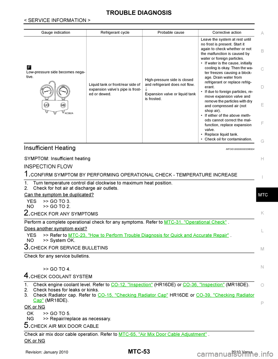
Low-pressure side becomes nega-
tive. Liquid tank or front/rear side of
expansion valve’s pipe is frost-
ed or dewed.High-pressure side is closed
and refrigerant does not flow.
↓
Expansion valve or liquid tank
is frosted.Leave the system at rest until
no frost is present. Start it
again to check whether or not
the malfunction is caused by
water or foreign particles.
• If water is the cause, initially
cooling is okay. Then the wa-
ter freezes causing a block-
age. Drain water from
refrigerant or replace refrig-
erant.
• If due to foreign particles, re-
move expansion valve and
remove the particles with dry
and compressed air (not
shop air).
• If either of the above meth- ods cannot correct the mal-
function, replace expansion
valve.
• Replace liquid tank.
• Check oil for contamination.
AC362A
Revision: January 20102010 Versa
Page 3334 of 3745
TROUBLE DIAGNOSISMTC-55
< SERVICE INFORMATION >
C
DE
F
G H
I
K L
M A
B
MTC
N
O P
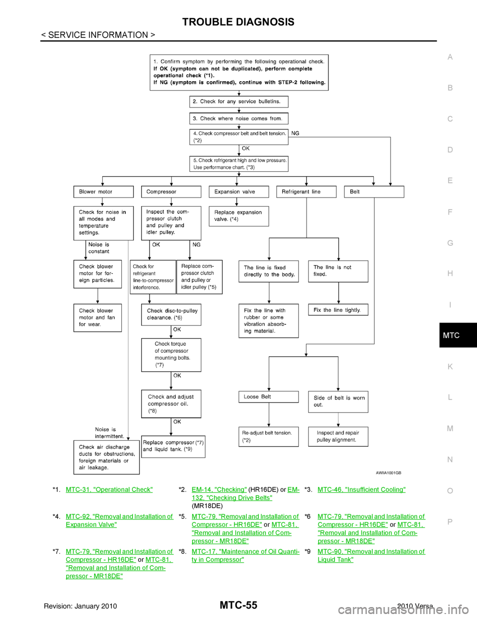
*1. MTC-31, "Operational Check"*2.EM-14, "Checking" (HR16DE) or EM-
132, "Checking Drive Belts"
(MR18DE) *3.
MTC-46, "
Insufficient Cooling"
*4.MTC-92, "Removal and Installation of
Expansion Valve"
*5.MTC-79, "Removal and Installation of
Compressor - HR16DE" or MTC-81,
"Removal and Installation of Com-
pressor - MR18DE"
*6 MTC-79, "Removal and Installation of
Compressor - HR16DE" or MTC-81,
"Removal and Installation of Com-
pressor - MR18DE"
*7. MTC-79, "Removal and Installation of
Compressor - HR16DE" or MTC-81,
"Removal and Installation of Com-
pressor - MR18DE"
*8.MTC-17, "Maintenance of Oil Quanti-
ty in Compressor"
*9 MTC-90, "Removal and Installation of
Liquid Tank"
AWIIA1001GB
Revision: January 20102010 Versa
Page 3340 of 3745
A/C UNIT ASSEMBLYMTC-61
< SERVICE INFORMATION >
C
DE
F
G H
I
K L
M A
B
MTC
N
O P
Disassembly and AssemblyINFOID:0000000005396510
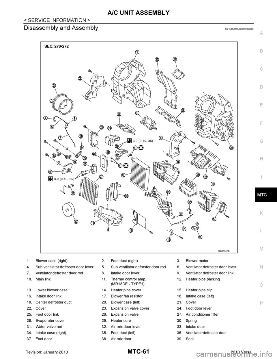
1. Blower case (right) 2. Foot duct (right) 3. Blower motor
4. Sub ventilator·defroster door lever 5. Sub ventilator·defroster door rod 6. Ventilator·defroster door lever
7. Ventilator·defroster door rod 8. Intake door lever 9. Ventilator·defroster door link
10. Main link 11. Thermo control amp.
(MR18DE - TYPE1) 12. Heater pipe packing
13. Lower blower case 14. Heater pipe cover 15. Heater pipe clip
16. Intake door link 17. Blower fan resistor 18. Intake case (left)
19. Center defroster duct 20. Blower case (left) 21. Cover
22. Cover 23. Expansion valve cover 24. Foot door lever
25. Foot door link 26. Expansion valve 27. Air conditioner filter
28. Evaporator cover 29. Heater core 30. Spring
31. Water valve rod 32. Air mix door lever 33. Intake door
34. Intake case (right) 35. Foot duct (left) 36. Ventilator·defroster door
37. Foot door 38. Air mix door 39. Seal
SJIA1515E
Revision: January 20102010 Versa
Page 3341 of 3745

MTC-62
< SERVICE INFORMATION >
A/C UNIT ASSEMBLY
40. Expansion valve grommet41. O-ring 42. Evaporator
43. Cooler pipe assembly
Revision: January 20102010 Versa