2010 NISSAN TIIDA Accelerator
[x] Cancel search: AcceleratorPage 213 of 3745

AT-196
< SERVICE INFORMATION >
TROUBLE DIAGNOSIS FOR SYMPTOMS
OK >>INSPECTION END
NG >> GO TO 3.
3.CHECK TCM
1. Check TCM input/output signals. Refer to AT-75, "
TCM Terminal and Reference Value" .
2. If NG, recheck TCM pin terminals for damage or loose connection with harness connector.
OK or NG
OK >> INSPECTION END
NG >> Repair or replace damaged parts.
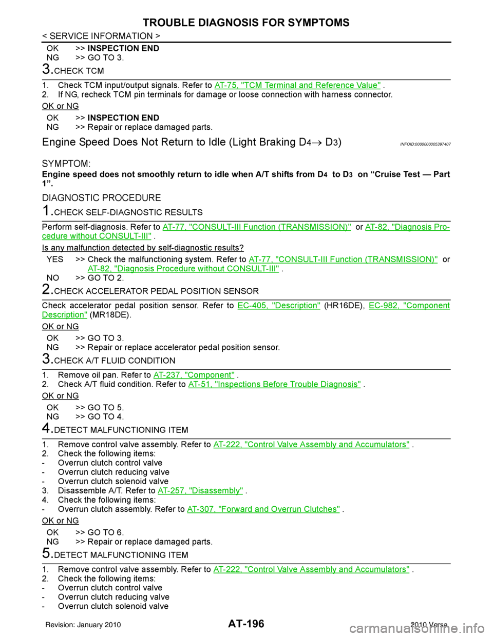
Engine Speed Does Not Return to Idle (Light Braking D4→ D3)INFOID:0000000005397407
SYMPTOM:
Engine speed does not smoothly return to idle when A/T shifts from D4 to D3 on “Cruise Test — Part
1”.
DIAGNOSTIC PROCEDURE
1.CHECK SELF-DIAGNOSTIC RESULTS
Perform self-diagnosis. Refer to AT-77, "
CONSULT-III Function (TRANSMISSION)" or AT-82, "Diagnosis Pro-
cedure without CONSULT-III" .
Is any malfunction detected by self-diagnostic results?
YES >> Check the malfunctioning system. Refer to AT-77, "CONSULT-III Function (TRANSMISSION)" or
AT-82, "
Diagnosis Procedure without CONSULT-III" .
NO >> GO TO 2.
2.CHECK ACCELERATOR PEDAL POSITION SENSOR
Check accelerator pedal position sensor. Refer to EC-405, "
Description" (HR16DE), EC-982, "Component
Description" (MR18DE).
OK or NG
OK >> GO TO 3.
NG >> Repair or replace accelerator pedal position sensor.
3.CHECK A/T FLUID CONDITION
1. Remove oil pan. Refer to AT-237, "
Component" .
2. Check A/T fluid condition. Refer to AT-51, "
Inspections Before Trouble Diagnosis" .
OK or NG
OK >> GO TO 5.
NG >> GO TO 4.
4.DETECT MALFUNCTIONING ITEM
1. Remove control valve assembly. Refer to AT-222, "
Control Valve Assembly and Accumulators" .
2. Check the following items:
- Overrun clutch control valve
- Overrun clutch reducing valve
- Overrun clutch solenoid valve
3. Disassemble A/T. Refer to AT-257, "
Disassembly" .
4. Check the following items:
- Overrun clutch assembly. Refer to AT-307, "
Forward and Overrun Clutches" .
OK or NG
OK >> GO TO 6.
NG >> Repair or replace damaged parts.
5.DETECT MALFUNCTIONING ITEM
1. Remove control valve assembly. Refer to AT-222, "
Control Valve Assembly and Accumulators" .
2. Check the following items:
- Overrun clutch control valve
- Overrun clutch reducing valve
- Overrun clutch solenoid valve
Revision: January 20102010 Versa
Page 220 of 3745

TROUBLE DIAGNOSIS FOR SYMPTOMSAT-203
< SERVICE INFORMATION >
DE
F
G H
I
J
K L
M A
B
AT
N
O P
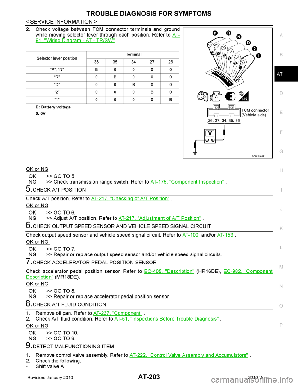
2. Check voltage between TCM connector terminals and ground while moving selector lever through each position. Refer to AT-
91, "Wiring Diagram - AT - TR/SW" .
B: Battery voltage
0: 0V
OK or NG
OK >> GO TO 5
NG >> Check transmission range switch. Refer to AT-175, "
Component Inspection" .
5.CHECK A/T POSITION
Check A/T position. Refer to AT-217, "
Checking of A/T Position" .
OK or NG
OK >> GO TO 6.
NG >> Adjust A/T position. Refer to AT-217, "
Adjustment of A/T Position" .
6.CHECK OUTPUT SPEED SENSOR AND VEHICLE SPEED SIGNAL CIRCUIT
Check output speed sensor and vehicle speed signal circuit. Refer to AT-100
and/or AT- 1 5 3 .
OK or NG
OK >> GO TO 7.
NG >> Repair or replace output speed sensor and/or vehicle speed signal circuits.
7.CHECK ACCELERATOR PEDAL POSITION SENSOR
Check accelerator pedal position sensor. Refer to EC-405, "
Description" (HR16DE), EC-982, "Component
Description" (MR18DE).
OK or NG
OK >> GO TO 8.
NG >> Repair or replace accelerator pedal position sensor.
8.CHECK A/T FLUID CONDITION
1. Remove oil pan. Refer to AT-237, "
Component" .
2. Check A/T fluid condition. Refer to AT-51, "
Inspections Before Trouble Diagnosis" .
OK or NG
OK >> GO TO 10.
NG >> GO TO 9.
9.DETECT MALFUNCTIONING ITEM
1. Remove control valve assembly. Refer to AT-222, "
Control Valve Assembly and Accumulators" .
2. Check the following.
- Shift valve A
Selector lever position Te r m i n a l
36 35 34 27 26
“P”, “N” B 0 0 0 0
“R” 0B000
“D” 0 0 B 0 0
“2” 0 0 0 B 0
“1” 0 0 0 0 B
SCIA7162E
Revision: January 20102010 Versa
Page 222 of 3745

TROUBLE DIAGNOSIS FOR SYMPTOMSAT-205
< SERVICE INFORMATION >
DE
F
G H
I
J
K L
M A
B
AT
N
O P
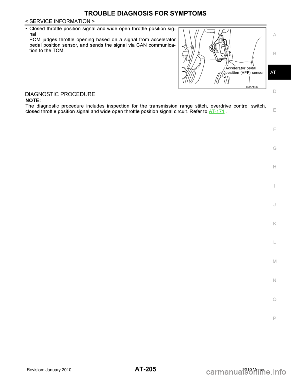
• Closed throttle position signal and wide open throttle position sig- nal
ECM judges throttle opening based on a signal from accelerator
pedal position sensor, and sends the signal via CAN communica-
tion to the TCM.
DIAGNOSTIC PROCEDURE
NOTE:
The diagnostic procedure includes inspection for the tr ansmission range stitch, overdrive control switch,
closed throttle position signal and wide open throttle position signal circuit. Refer to AT-171
.
SCIA7143E
Revision: January 20102010 Versa
Page 390 of 3745

SERVICE DATA AND SPECIFICATIONS (SDS)AT-373
< SERVICE INFORMATION >
DE
F
G H
I
J
K L
M A
B
AT
N
O P
SERVICE DATA AND SPECIFICATIONS (SDS)
General SpecificationINFOID:0000000005397455
*: Refer to MA-14.
Vehicle Speed at Which Gear Shifting OccursINFOID:0000000005397456
HR16DE engine models
MR18DE engine models
• At half throttle, the accelerator opening is 4/8 of the full opening.
Vehicle Speed at When Lock-up Occurs/ReleasesINFOID:0000000005397457
HR16DE engine models
MR18DE engine models
Engine HR16DEMR18DE
Automatic transaxle model RE4F03B
Automatic transaxle assembly Model code number 3CX3D, 3CX3E3CX0D
Transaxle gear ratio 1st
2.861
2nd 1.562
3rd 1.000
4th 0.697
Reverse 2.310
Final drive 4.072
Recommended fluid Genuine NISSAN Matic S ATF (Continental U.S. and Alaska) or
Canada NISSAN Automatic Transmission Fluid*
Fluid capacity [ (US qt, Imp qt)] 7.7 (8-1/8, 6-3/4)
7.9 (8-3/8, 7)
Throttle position Vehicle speed km/h (MPH)
D1 → D2D2 → D3D3 → D4D4 → D3D3 → D2D2 → D1
Full throttle 49 - 57
(31 - 35) 93 - 101
(58 - 62) 148 - 156
(92 - 96) 144 - 152
(90 - 94) 82 - 90
(51 - 55) 39 - 47
(25 - 29)
Half throttle 35 - 43
(22 - 26) 59 - 67
(37 - 41) 117 - 125
(73 - 77) 59 - 67
(37 - 41) 34 - 42
(22 - 26) 15 - 23
(10 - 14)
Throttle position Vehicle speed km/h (MPH)
D
1 → D2D2 → D3D3 → D4D4 → D3D3 → D2D2 → D1
Full throttle 51 - 59
(32 - 37) 97 - 105
(60 - 65) 154 - 162
(96 - 101) 150 - 158
(93 - 98) 87 - 95
(54 - 59) 40 - 48
(25 - 30)
Half throttle 34 - 42
(21 - 26) 62 - 70
(39 - 43) 124 - 132
(77 - 82) 69 - 77
(43 - 48) 36 - 44
(22 - 27) 19 - 27
(12 - 17)
Throttle position Selector lever position Vehicle speed km/h (MPH)
Lock-up ON Lock-up OFF
2.0/8 “D” position
73 - 81 (46 - 50) 49 - 57 (31 - 35)
“D” position (OD OFF) 86 - 94 (53 - 58) 82 - 90 (51 - 55)
Throttle position Selector lever position Vehicle speed km/h (MPH)
Lock-up ON Lock-up OFF
2.0/8 “D” position
86 - 94 (53 - 58) 59 - 67 (37 - 42)
“D” position (OD OFF) 86 - 94 (53 - 58) 83 - 91 (52 - 57)
Revision: January 20102010 Versa
Page 856 of 3745

BR-8
< SERVICE INFORMATION >
BRAKE PEDAL
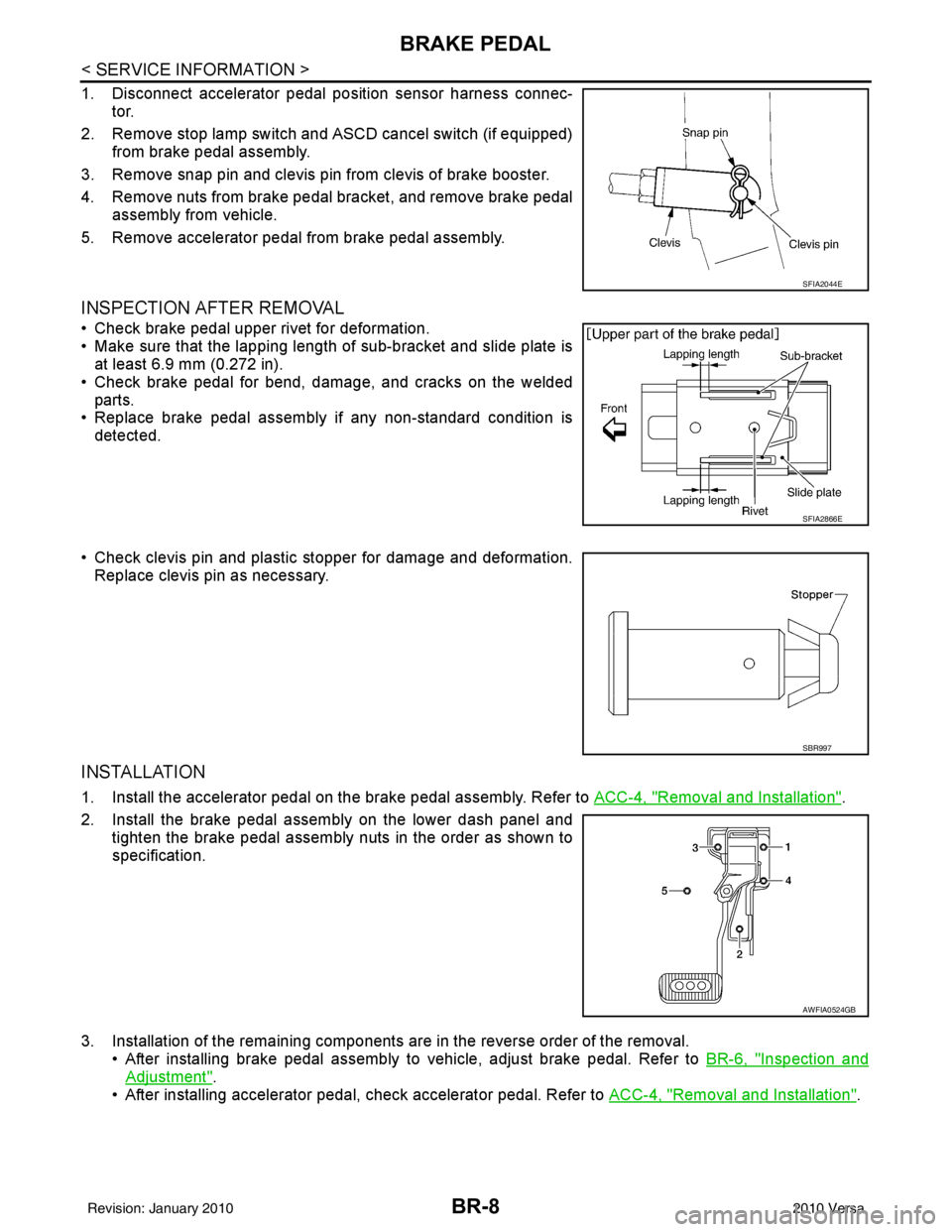
1. Disconnect accelerator pedal position sensor harness connec-tor.
2. Remove stop lamp switch and ASCD cancel switch (if equipped) from brake pedal assembly.
3. Remove snap pin and clevis pin from clevis of brake booster.
4. Remove nuts from brake pedal bracket, and remove brake pedal assembly from vehicle.
5. Remove accelerator pedal from brake pedal assembly.
INSPECTION AFTER REMOVAL
• Check brake pedal upper rivet for deformation.
• Make sure that the lapping length of sub-bracket and slide plate is at least 6.9 mm (0.272 in).
• Check brake pedal for bend, damage, and cracks on the welded parts.
• Replace brake pedal assembly if any non-standard condition is
detected.
• Check clevis pin and plastic stopper for damage and deformation. Replace clevis pin as necessary.
INSTALLATION
1. Install the accelerator pedal on the brake pedal assembly. Refer to ACC-4, "Removal and Installation".
2. Install the brake pedal assembly on the lower dash panel and tighten the brake pedal assembly nuts in the order as shown to
specification.
3. Installation of the remaining components are in the reverse order of the removal. • After installing brake pedal assembly to vehicle, adjust brake pedal. Refer to BR-6, "
Inspection and
Adjustment".
• After installing accelerator pedal, check accelerator pedal. Refer to ACC-4, "
Removal and Installation".
SFIA2044E
SFIA2866E
SBR997
AWFIA0524GB
Revision: January 20102010 Versa
Page 949 of 3745
![NISSAN TIIDA 2010 Service Repair Manual TROUBLE DIAGNOSISBRC-59
< SERVICE INFORMATION > [VDC/TCS/ABS]
C
D
E
G H
I
J
K L
M A
B
BRC
N
O P
ACCEL POS SIG Open/close condition
of throttle valve (linked
with accelerator pedal)Accelerator pedal NISSAN TIIDA 2010 Service Repair Manual TROUBLE DIAGNOSISBRC-59
< SERVICE INFORMATION > [VDC/TCS/ABS]
C
D
E
G H
I
J
K L
M A
B
BRC
N
O P
ACCEL POS SIG Open/close condition
of throttle valve (linked
with accelerator pedal)Accelerator pedal](/manual-img/5/57397/w960_57397-948.png)
TROUBLE DIAGNOSISBRC-59
< SERVICE INFORMATION > [VDC/TCS/ABS]
C
D
E
G H
I
J
K L
M A
B
BRC
N
O P
ACCEL POS SIG Open/close condition
of throttle valve (linked
with accelerator pedal)Accelerator pedal not de-
pressed (ignition switch is ON)
0%
BRC-79, "
CAN Commu-
nication System Inspec-
tion"Depress accelerator pedal (ig-
nition switch is ON) 0 to 100%
SIDE G-SENSOR Transverse G detected
by side G-sensorVehicle stopped
Approx. 0 m/s
2
BRC-70, "Yaw Rate/Side/
Decel G Sensor System
Inspection"
Vehicle turning rightnegative value (m/
s2)
Vehicle turning left positive value (m/
s
2)
STR ANGLE SIG Steering angle detect-
ed by steering angle
sensorStraight-ahead
Approx. 0°BRC-69, "
Steering Angle
Sensor System Inspec-
tion"Steering wheel turned –720 to 720 °
PRESS SENSOR Brake fluid pressure
detected by pressure
sensorWith ignition switch ON and
brake pedal released
Approx. 0 bar
BRC-77, "
Pressure Sen-
sor System Inspection"With ignition switch ON and
brake pedal depressed –40 to 300 bar
EBD SIGNAL EBD operation EBD is active
On
—
EBD is inactive Off
ABS SIGNAL ABS operationABS is active
On
—
ABS is inactive Off
TCS SIGNAL TCS operationTCS is active
On
—
TCS is inactive Off
VDC SIGNAL VDC operationVDC is active
On
—
VDC is inactive Off
EBD FAIL SIG EBD fail-safe signal In EBD fail safe mode On
—
EBD is normal Off
ABS FAIL SIG ABS fail-safe signal In ABS fail safe mode
On
—
ABS is normal Off
TCS FAIL SIG TCS fail-safe signal In TCS fail safe mode
On
—
TCS is normal Off
VDC FAIL SIG VDC fail-safe signal In VDC fail safe mode On
—
VDC is normal Off
CRANKING SIG Crank operation Crank is active
On
—
Crank is inactive Off
FLUID LEV SW Status of brake fluid
level switchWhen brake fluid level switch
ON
On
BRC-76, "
Brake Fluid
Level Switch System In-
spection"When brake fluid level switch
OFF Off
PARK BRAKE SW Status of parking brake
switchParking brake switch is active On
BRC-79, "
Component In-
spection"Parking brake switch is inactive Off
Monitor item Display content
Data monitor
Note: Error inspection
checklist
Condition Reference value in
normal operation
Revision: January 20102010 Versa
Page 1042 of 3745
![NISSAN TIIDA 2010 Service Repair Manual PRECAUTIONSCVT-9
< SERVICE INFORMATION > [RE0F08B]
D
E
F
G H
I
J
K L
M A
B
CVT
N
O P
6. Turn ignition switch ON. CAUTION:
Never start engine.
7. Select “Self Diagnostic Results” in “TRANSMISSION NISSAN TIIDA 2010 Service Repair Manual PRECAUTIONSCVT-9
< SERVICE INFORMATION > [RE0F08B]
D
E
F
G H
I
J
K L
M A
B
CVT
N
O P
6. Turn ignition switch ON. CAUTION:
Never start engine.
7. Select “Self Diagnostic Results” in “TRANSMISSION](/manual-img/5/57397/w960_57397-1041.png)
PRECAUTIONSCVT-9
< SERVICE INFORMATION > [RE0F08B]
D
E
F
G H
I
J
K L
M A
B
CVT
N
O P
6. Turn ignition switch ON. CAUTION:
Never start engine.
7. Select “Self Diagnostic Results” in “TRANSMISSION”.
8. Shift the selector lever to “R” position.
9. Depress slightly the accelerator pedal (Pedal angle: 2/8) while depressing the brake pedal.
10. Select “Erase” with step 9.
11. Release brake pedal and accelerator pedal.
12. Turn ignition switch OFF while keeping the selector lever in “R” position.
13. Wait approximately 10 seconds.
14. Turn ignition switch ON while keeping the selector lever in “R” position.
15. Select “Special function” in “TRANSMISSION”.
16. Check that the value on “CALIB DATA” in CONSULT-II I is the same as the data listed in the table below.
• Restart the procedure from step 3 if the values are not the same.
CALIB DATA
17. Shift the selector lever to “P” position.
18. Check that the shift position indicator in combinat ion meter turns ON. (It indicates approximately 1 or 2
seconds after shifting the selector lever to “P” position.)
• Check the following items if shift position indicator does not turn ON. Repair or replace accordingly as
necessary.
- The harness between TCM and ROM ASSY in transaxle assembly is open or shorted.
- Terminals disconnected, loose, or bent from connector housing.
- Power supply and ground of TCM. Refer to CVT-113, "
Description".
PATTERN C
1. Replace transaxle assembly first, and then replace TCM.
2. Perform the service of “PATTERN A”.
(Perform the service of “PATTERN B” if TCM is replaced first.)
Removal and Installation Procedure for CVT Unit ConnectorINFOID:0000000005397762
REMOVAL
Rotate bayonet ring counterclockwise, pull out CVT unit harness
connector upward and disconnect it.
INSTALLATION
Item name Display value
UNIT CLB ID 1 00
UNIT CLB ID 2 00
UNIT CLB ID 3 00
UNIT CLB ID 4 00
UNIT CLB ID 5 00
UNIT CLB ID 6 00
SCIA2096E
Revision: January 20102010 Versa
Page 1054 of 3745
![NISSAN TIIDA 2010 Service Repair Manual CVT SYSTEMCVT-21
< SERVICE INFORMATION > [RE0F08B]
D
E
F
G H
I
J
K L
M A
B
CVT
N
O P
Hydraulic Control SystemINFOID:0000000005397772
TCM FunctionINFOID:0000000005397773
The function of the TCM is to:
NISSAN TIIDA 2010 Service Repair Manual CVT SYSTEMCVT-21
< SERVICE INFORMATION > [RE0F08B]
D
E
F
G H
I
J
K L
M A
B
CVT
N
O P
Hydraulic Control SystemINFOID:0000000005397772
TCM FunctionINFOID:0000000005397773
The function of the TCM is to:](/manual-img/5/57397/w960_57397-1053.png)
CVT SYSTEMCVT-21
< SERVICE INFORMATION > [RE0F08B]
D
E
F
G H
I
J
K L
M A
B
CVT
N
O P
Hydraulic Control SystemINFOID:0000000005397772
TCM FunctionINFOID:0000000005397773
The function of the TCM is to:
• Receive input signals sent from various switches and sensors.
• Determine required line pressure, shifting point, and lock-up operation.
• Send required output signals to the step motor and the respective solenoids.
CONTROL SYSTEM OUTLINE
The CVT senses vehicle operating conditions through various sensors. It always controls the optimum shift
position and reduces shifting and lock-up shocks.
AWDIA0768GB
SENSORS (or SIGNAL)
⇒TCM
⇒ACTUATORS
Transmission range switch
Accelerator pedal position signal
Closed throttle position signal
Engine speed signal
CVT fluid temperature sensor
Vehicle speed signal
Overdrive control signal
Stop lamp switch signal
Primary speed sensor
Secondary speed sensor
Secondary pressure sensor Shift control
Line pressure control
Primary pressure control
Secondary pressure control
Lock-up control
Engine brake control
Vehicle speed control
Fail-safe control
Self-diagnosis
CONSULT-III co
mmunication
line
Duet-EA control
CAN system
On board diagnosis Step motor
Torque converter clutch solenoid
valve
Lock-up select solenoid valve
Line pressure solenoid valve
Secondary pressure solenoid
valve
Shift position indicator
O/D OFF indicator lamp
Starter relay
Revision: January 20102010 Versa