2010 NISSAN TIIDA throttle control
[x] Cancel search: throttle controlPage 140 of 3745

P0740 TORQUE CONVERTERAT-123
< SERVICE INFORMATION >
DE
F
G H
I
J
K L
M A
B
AT
N
O P
P0740 TORQUE CONVERTER
DescriptionINFOID:0000000005397310
• The torque converter clutch solenoid valve is activated, with the gear in D4 and D3, by the TCM in response
to signals sent from the output speed sensor and t he ECM (throttle opening). Lock-up piston operation will
then be controlled.
• Lock-up operation, however, is prohibited when A/T fluid temperature is too low.
• When the accelerator pedal is depressed (less than 2/8) on lock-up condition, the engine speed should not
change abruptly. If there is an abrupt change in engine speed, there is no lock-up.
CONSULT-III Reference Val ue in Data Monitor ModeINFOID:0000000005397311
Remarks: Specification data are reference values.
On Board Diagnosis LogicINFOID:0000000005397312
• This is an OBD-II self-diagnostic item.
• Diagnostic trouble code “P0740 T/C CLUTCH SOL” with CO NSULT-III or 7th judgement flicker without CON-
SULT-III is detected when TCM detects an improper vo ltage drop while it tries to operate solenoid valve.
Possible CauseINFOID:0000000005397313
• Torque converter clutch solenoid valve
• Harness or connector
(The solenoid circuit is open or shorted.)
DTC Confirmation ProcedureINFOID:0000000005397314
CAUTION:
• Always drive vehicle at a safe speed.
• If performing this “DTC Confirmation Procedure” again, always turn ignition switch OFF and wait at
least 10 seconds before continuing.
After the repair, perform the following procedure to confirm the malfunction is eliminated.
WITH CONSULT-III
1. Turn ignition switch ON. (Do not start engine.)
2. Select “DATA MONITOR” mode for “TRANSMISSION” with CONSULT-III and wait at least 1 second.
3. Touch “START”.
4. Start engine and maintain the following conditions for at least 5 consecutive seconds. VEHICLE SPEED: 80 km/h (50 MPH) or more
THROTTLE POSI: 0.5/8 - 1.0/8
SLCT LVR POSI: “D” position
Driving location: Driving the vehic le uphill (increased engine load) will help maintain the driving
conditions required for this test.
5. If the check result is NG, go to AT-125, "
Diagnosis Procedure".
WITH GST
Follow the procedure “WITH CONSULT-III”.
WITHOUT CONSULT-III
1. Start engine.
2. Drive vehicle in D
1→ D2→ D3→ D4→ D4 lock-up position.
3. Perform self-diagnosis. Refer to AT-82, "
Diagnosis Procedure without CONSULT-III" .
4. If the check result is NG, go to AT-125, "
Diagnosis Procedure" .
Item nameCondition Display value (Approx)
TCC S/V DUTY Lock-up OFF ⇔ Lock-up ON 4% ⇔ 94%
Revision: January 20102010 Versa
Page 146 of 3745
P0744 TORQUE CONVERTERAT-129
< SERVICE INFORMATION >
DE
F
G H
I
J
K L
M A
B
AT
N
O P
5. Accelerate vehicle to more than 80 km/h (50 MPH) and maintain the following conditions continuously until “TESTING” has turned to “COMPLETE”. (It will take approximately 30 seconds after “TESTING”
shows.)
THROTTLE POSI: 1.0/8 - 2.0/8 (a t all times during step 4)
SLCT LVR POSI: “D” position
TCC S/V DUTY: More than 94%
VEHICLE SPEED: Constant speed of more than 80 km/h (50 MPH)
- Make sure that “GEAR” shows “4”.
- For shift schedule, refer to AT-64, "
Vehicle Speed at Which Gear Shifting Occurs".
- If “TESTING” does not appear on CONSULT-III for a long time, select “SELF-DIAG RESULTS”. In
case a DTC other than “P0744 T/C CLUT CH FNCTN” is shown, refer to AT- 7 7 , "
CONSULT-III Func-
tion (TRANSMISSION)".
6. Make sure that “OK” is disp layed. (If “NG” is displayed, refer to “DIAGNOSTIC PROCEDURE”.)
Refer to AT-129, "
Diagnosis Procedure".
Refer to AT-64, "
Vehicle Speed at Which Lock-up Occurs/Releases".
WITH GST
Follow the procedure “WITH CONSULT-III”.
Diagnosis ProcedureINFOID:0000000005397323
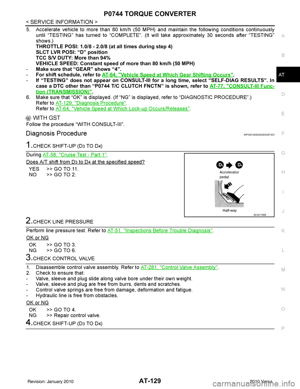
1.CHECK SHIFT-UP (D3 TO D4)
During AT-58, "
Cruise Test - Part 1".
Does A/T shift from D
3 to D4 at the specified speed?
YES >> GO TO 11.
NO >> GO TO 2.
2.CHECK LINE PRESSURE
Perform line pressure test. Refer to AT-51, "
Inspections Before Trouble Diagnosis".
OK or NG
OK >> GO TO 3.
NG >> GO TO 6.
3.CHECK CONTROL VALVE
1. Disassemble control valve assembly. Refer to AT-281, "
Control Valve Assembly".
2. Check to ensure that:
- Valve, sleeve and plug slide along valve bore under their own weight.
- Valve, sleeve and plug are free from burrs, dents and scratches.
- Control valve springs are free from damage, deformation and fatigue.
- Hydraulic line is free from obstacles.
OK or NG
OK >> GO TO 4.
NG >> Repair control valve.
4.CHECK SHIFT-UP (D3 TO D4)
SCIA7190E
Revision: January 20102010 Versa
Page 150 of 3745
P0745 PRESSURE CONTROL SOLENOID AAT-133
< SERVICE INFORMATION >
DE
F
G H
I
J
K L
M A
B
AT
N
O P
P0745 PRESSURE CONTROL SOLENOID A
DescriptionINFOID:0000000005397324
The line pressure solenoid valve regulates the oil pum p discharge pressure to suit the driving condition in
response to signals sent from the TCM.
The line pressure duty cycle value is not constant when the closed throttle po sition switch is ON. To
confirm the line pressure duty cycle at low-pressure, the accelerator (throttle) sh ould be open until the
closed throttle position switch is OFF.
CONSULT-III Reference Val ue in Data Monitor ModeINFOID:0000000005397325
Remarks: Specification data are reference values.
On Board Diagnosis LogicINFOID:0000000005397326
• This is an OBD-II self-diagnostic item.
• Diagnostic trouble code “P0745 PC SOLENOID A” with CO NSULT-III or 11th judgement flicker without CON-
SULT-III is detected when TCM detects an improper volt age drop while it tries to operate the solenoid valve.
Possible CauseINFOID:0000000005397327
• Harness or connector
(The solenoid circuit is open or shorted.)
• Line pressure solenoid valve
DTC Confirmation ProcedureINFOID:0000000005397328
CAUTION:
If performing this “DTC Confirmati on Procedure” again, always turn ignition switch OFF and wait at
least 10 seconds before continuing.
After the repair, perform the following procedure to confirm the malfunction is eliminated.
WITH CONSULT-III
1. Turn ignition switch ON and select “DATA MO NITOR” mode for “TRANSMISSION” with CONSULT-III.
2. Touch “START”.
3. Depress accelerator pedal completely and wait at least 1 second.
4. If the check result is NG, go to AT-135, "
Diagnosis Procedure" .
WITH GST
Follow the procedure “WITH CONSULT-III”.
WITHOUT CONSULT-III
1. Start engine.
2. With brake pedal depressed, shift the lever from “P” →“N” →“D” →“N” →“P” positions.
3. Perform self-diagnosis. Refer to AT-82, "
Diagnosis Procedure without CONSULT-III" .
4. If the check result is NG, go to AT-135, "
Diagnosis Procedure" .
Item nameCondition Display value (Approx.)
LINE PRES DTY Small throttle opening (Low line pressure)
⇔ Large
throttle opening (High line pressure) 0%
⇔ 94%
Revision: January 20102010 Versa
Page 152 of 3745
P0745 PRESSURE CONTROL SOLENOID AAT-135
< SERVICE INFORMATION >
DE
F
G H
I
J
K L
M A
B
AT
N
O P
Diagnosis ProcedureINFOID:0000000005397330
1.CHECK INPUT SIGNALWith CONSULT-III
1. Turn ignition switch ON. (Do not start engine.)
2. Select “MAIN SIGNALS” in “DATA MONITOR” mode for “TRANSMISSION” with CONSULT-III.
3. Read out the value of “LINE PRES DTY” while driv ing. Check the value changes according to driving
speed.
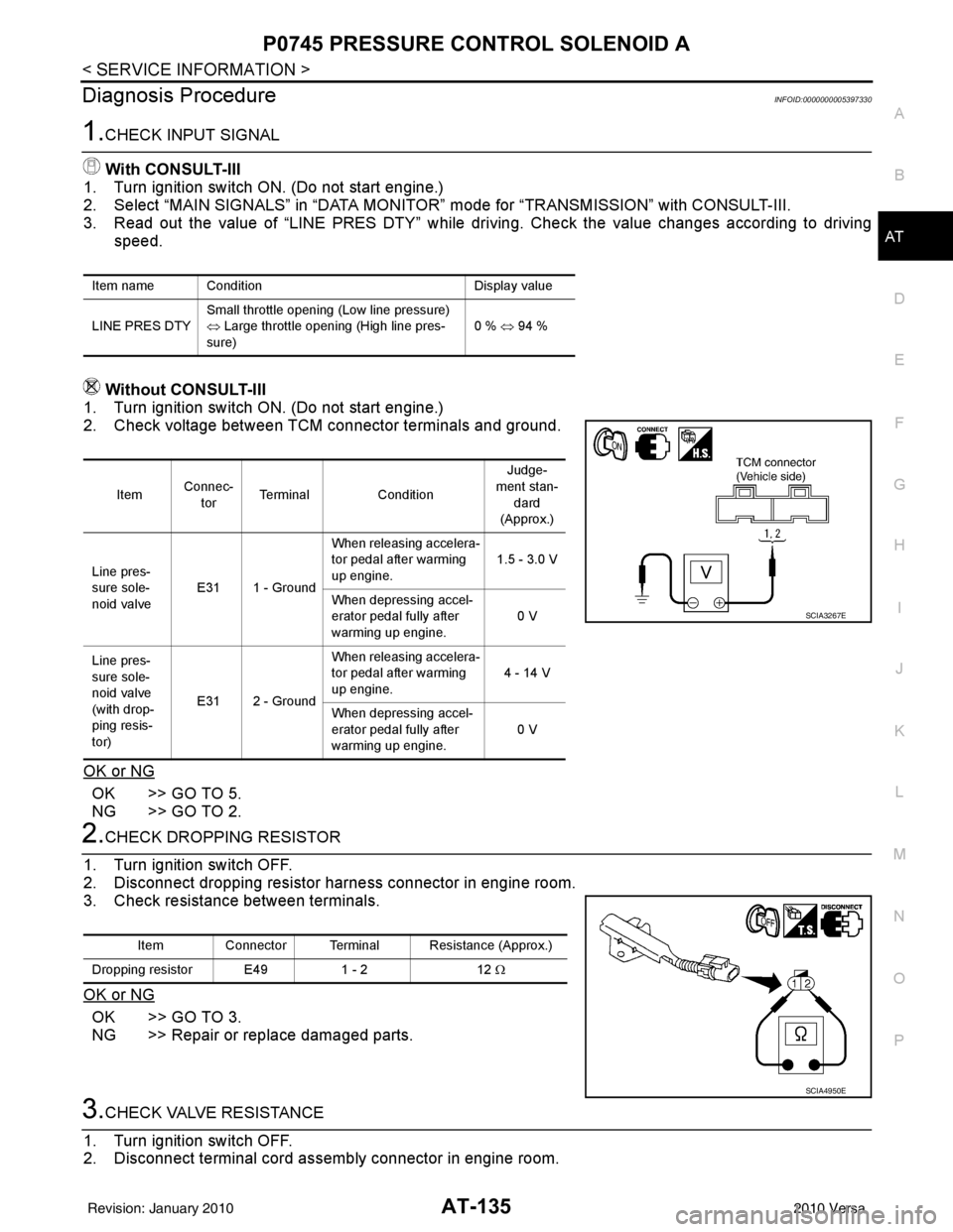
Without CONSULT-III
1. Turn ignition switch ON. (Do not start engine.)
2. Check voltage between TCM connector terminals and ground.
OK or NG
OK >> GO TO 5.
NG >> GO TO 2.
2.CHECK DROPPING RESISTOR
1. Turn ignition switch OFF.
2. Disconnect dropping resistor har ness connector in engine room.
3. Check resistance between terminals.
OK or NG
OK >> GO TO 3.
NG >> Repair or replace damaged parts.
3.CHECK VALVE RESISTANCE
1. Turn ignition switch OFF.
2. Disconnect terminal cord assembly connector in engine room.
Item name Condition Display value
LINE PRES DTY Small throttle opening (Low line pressure)
⇔
Large throttle opening (High line pres-
sure) 0 % ⇔
94 %
Item Connec-
tor Terminal
Condition Judge-
ment stan- dard
(Approx.)
Line pres-
sure sole-
noid valve E31 1 - Ground When releasing accelera-
tor pedal after warming
up engine.
1.5 - 3.0 V
When depressing accel-
erator pedal fully after
warming up engine. 0 V
Line pres-
sure sole-
noid valve
(with drop-
ping resis-
tor) E31 2 - Ground When releasing accelera-
tor pedal after warming
up engine.
4 - 14 V
When depressing accel-
erator pedal fully after
warming up engine. 0 V
SCIA3267E
Item Connector Terminal Resistance (Approx.)
Dropping resistor E49 1 - 212 Ω
SCIA4950E
Revision: January 20102010 Versa
Page 165 of 3745
AT-148
< SERVICE INFORMATION >
P1760 OVERRUN CLUTCH SOLENOID
P1760 OVERRUN CLUTCH SOLENOID
DescriptionINFOID:0000000005397348
The overrun clutch solenoid valve is activated by the TCM in response to signals sent from the transmission
range switch, overdrive control switch, vehicle speed and ECM (throttle opening). The overrun clutch opera-
tion will then be controlled.
CONSULT-III Reference Value in Data Monitor ModeINFOID:0000000005397349
On Board Diagn osis LogicINFOID:0000000005397350
• This is an OBD-II self-diagnostic item.
• Diagnostic trouble code “P1760 OVER CLUTCH SOLENOID ” with CONSULT-III or 6th judgement flicker
without CONSULT-III is detected when TCM detects an improper voltage drop when it tries to operate sole-
noid valve.
Possible CauseINFOID:0000000005397351
• Harness or connector
(The solenoid circuit is open or shorted.)
• Overrun clutch solenoid valve
DTC Confirmation ProcedureINFOID:0000000005397352
CAUTION:
• Always drive vehicle at a safe speed.
• If performing this “DTC Confirmation Procedure” again, always turn ignition switch OFF and wait at
least 10 seconds before continuing.
After the repair, perform the following proc edure to confirm the malfunction is eliminated.
WITH CONSULT-III
1. Turn ignition switch ON and select “DATA MONI TOR” mode for “TRANSMISSION” with CONSULT-III.
2. Touch “START”.
3. Start engine.
4. Accelerate vehicle to a speed of more t han 10 km/h (6 MPH) with “D” position (OD ON).
5. Release accelerator pedal completely with “D” position (OD OFF).
6. If the check result is NG, go to AT-150, "
Diagnosis Procedure".
WITH GST
Follow the procedure “WITH CONSULT-III”.
WITHOUT CONSULT-III
1. Start engine.
2. Drive vehicle under the following conditions:
Selector lever position: “D” position (OD ON)
Vehicle speed: Higher than 10 km/h (6 MPH)
3. Perform self-diagnosis. Refer to AT-82, "
Diagnosis Procedure without CONSULT-III" .
4. If the check result is NG, go to AT-150, "
Diagnosis Procedure" .
Item nameCondition Display value
OVERRUN/C S/V When overrun clutch solenoid valve operates. (When
overrun clutch disengaged. Refer to
AT- 2 2
.)ON
When overrun clutch solenoid valve does not operate.
(When overrun clutch engaged. Refer to AT- 2 2
.)OFF
Revision: January 20102010 Versa
Page 188 of 3745
TR SW, OD SW AND CLOSED THROTTLE, WIDE OPEN THROTTLE POSITION
SIGNAL CIRCUIT
AT-171
< SERVICE INFORMATION >
DE
F
G H
I
J
K L
M A
B
AT
N
O P
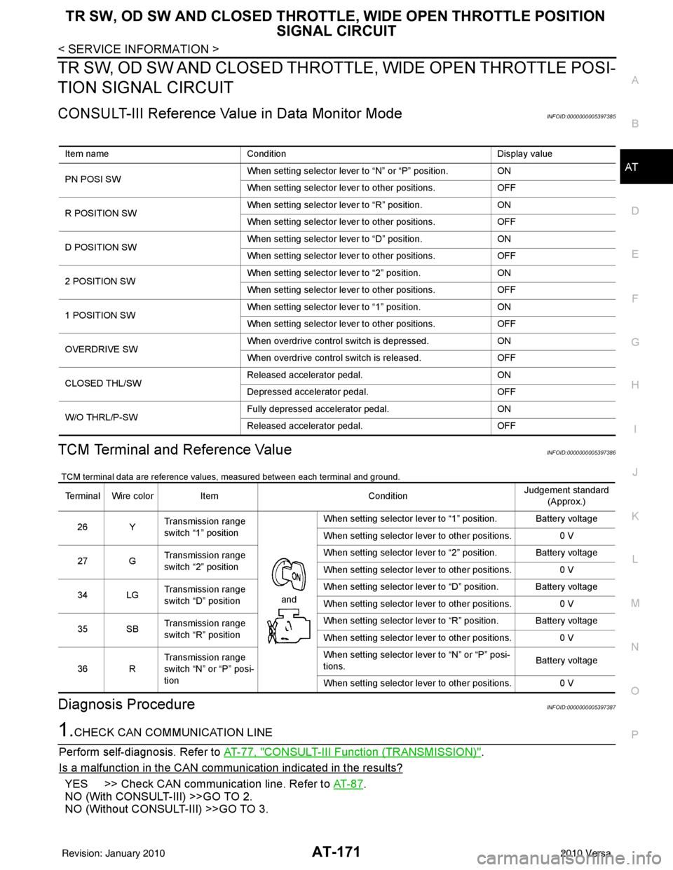
TR SW, OD SW AND CLOSED THROTTL E, WIDE OPEN THROTTLE POSI-
TION SIGNAL CIRCUIT
CONSULT-III Reference Val ue in Data Monitor ModeINFOID:0000000005397385
TCM Terminal and Reference ValueINFOID:0000000005397386
TCM terminal data are reference values, measured between each terminal and ground.
Diagnosis ProcedureINFOID:0000000005397387
1.CHECK CAN COMMUNICATION LINE
Perform self-diagnosis. Refer to AT-77, "
CONSULT-III Function (TRANSMISSION)".
Is a malfunction in the CAN communication indicated in the results?
YES >> Check CAN communication line. Refer to AT- 8 7.
NO (With CONSULT-III) >>GO TO 2.
NO (Without CONSULT-III) >>GO TO 3.
Item name Condition Display value
PN POSI SW When setting selector lever
to “N” or “P” position. ON
When setting selector lever to other positions. OFF
R POSITION SW When setting selector lever to “R” position.
ON
When setting selector lever to other positions. OFF
D POSITION SW When setting selector lever to “D” position.
ON
When setting selector lever to other positions. OFF
2 POSITION SW When setting selector lever to “2” position.
ON
When setting selector lever to other positions. OFF
1 POSITION SW When setting selector lever to “1” position.
ON
When setting selector lever to other positions. OFF
OVERDRIVE SW When overdrive control switch is depressed.
ON
When overdrive control switch is released. OFF
CLOSED THL/SW Released accelerator pedal.
ON
Depressed accelerator pedal. OFF
W/O THRL/P-SW Fully depressed accelerator pedal.
ON
Released accelerator pedal. OFF
Terminal Wire colorItem ConditionJudgement standard
(Approx.)
26 Y Transmission range
switch “1” position
andWhen setting selector lever to “1” position. Battery voltage
When setting selector lever to other positions.
0 V
27 G Transmission range
switch “2” position When setting selector lever to “2” position. Battery voltage
When setting selector lever to other positions.
0 V
34 LG Transmission range
switch “D” position When setting selector lever to “D” position. Battery voltage
When setting selector lever to other positions.
0 V
35 SB Transmission range
switch “R” position When setting selector lever to “R” position. Battery voltage
When setting selector lever to other positions.
0 V
36 R Transmission range
switch “N” or “P” posi-
tion When setting selector le
ver to “N” or “P” posi-
tions. Battery voltage
When setting selector lever to other positions. 0 V
Revision: January 20102010 Versa
Page 190 of 3745
TR SW, OD SW AND CLOSED THROTTLE, WIDE OPEN THROTTLE POSITION
SIGNAL CIRCUIT
AT-173
< SERVICE INFORMATION >
DE
F
G H
I
J
K L
M A
B
AT
N
O P
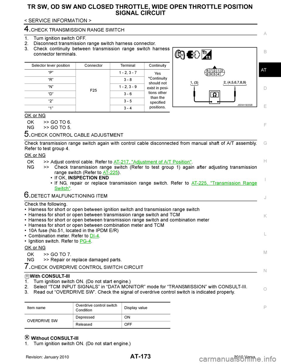
4.CHECK TRANSMISSION RANGE SWITCH
1. Turn ignition switch OFF.
2. Disconnect transmission range switch harness connector.
3. Check continuity between transmission range switch harness connector terminals.
OK or NG
OK >> GO TO 6.
NG >> GO TO 5.
5.CHECK CONTROL CABLE ADJUSTMENT
Check transmission range switch again with control cabl e disconnected from manual shaft of A/T assembly.
Refer to test group 4.
OK or NG
OK >> Adjust control cable. Refer to AT-217, "Adjustment of A/T Position".
NG >> Check transmission range switch (Refer to test group 1) again after adjusting transmission range switch (Refer to AT-225
).
• If OK, INSPECTION END
• If NG, repair or replace transmission range switch. Refer to AT-225, "
Transmission Range
Switch".
6.DETECT MALFUNCTIONING ITEM
Check the following.
• Harness for short or open between ignition switch and transmission range switch
• Harness for short or open between transmission range switch and TCM
• Harness for short or open between transmission range switch and combination meter
• Harness for short or open between combination meter and TCM
• 10A fuse (No.51, located in the IPDM E/R)
• Combination meter. Refer to DI-4
.
• Ignition switch. Refer to PG-4
.
OK or NG
OK >> GO TO 7.
NG >> Repair or replace damaged parts.
7.CHECK OVERDRIVE CO NTROL SWITCH CIRCUIT
With CONSULT-III
1. Turn ignition switch ON. (Do not start engine.)
2. Select “TCM INPUT SIGNALS” in “DATA MONI TOR” mode for “TRANSMISSION” with CONSULT-III.
3. Read out “OVERDRIVE SW”. Check the signal of ov erdrive control switch is indicated properly.
Without CONSULT-III
1. Turn ignition switch ON. (Do not start engine.)
Selector lever position Connector Terminal Continuity
“P”
F251 - 2, 3 - 7
Ye s
*Continuity should not
exist in posi-
tions other than the
specified
positions.
“R”
3 - 8
“N” 1 - 2, 3 - 9
“D” 3 - 6
“2” 3 - 5
“1” 3 - 4
JSDIA1503GB
Item nameOverdrive control switch
ConditionDisplay value
OVERDRIVE SW Depressed
ON
Released OFF
Revision: January 20102010 Versa
Page 191 of 3745
AT-174
< SERVICE INFORMATION >
TR SW, OD SW AND CLOSED THROTTLE, WIDE OPEN THROTTLE POSITION
SIGNAL CIRCUIT
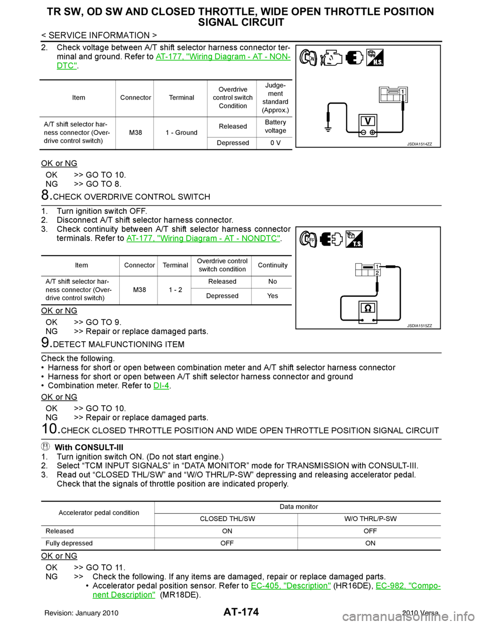
2. Check voltage between A/T shift selector harness connector ter-
minal and ground. Refer to AT-177, "
Wiring Diagram - AT - NON-
DTC".
OK or NG
OK >> GO TO 10.
NG >> GO TO 8.
8.CHECK OVERDRIVE CONTROL SWITCH
1. Turn ignition switch OFF.
2. Disconnect A/T shift selector harness connector.
3. Check continuity between A/T shift selector harness connector terminals. Refer to AT-177, "
Wiring Diagram - AT - NONDTC".
OK or NG
OK >> GO TO 9.
NG >> Repair or replace damaged parts.
9.DETECT MALFUNCTIONING ITEM
Check the following.
• Harness for short or open between combination meter and A/T shift selector harness connector
• Harness for short or open between A/T shift selector harness connector and ground
• Combination meter. Refer to DI-4
.
OK or NG
OK >> GO TO 10.
NG >> Repair or replace damaged parts.
10.CHECK CLOSED THROTTLE POSI TION AND WIDE OPEN THROTTLE POSITION SIGNAL CIRCUIT
With CONSULT-III
1. Turn ignition switch ON. (Do not start engine.)
2. Select “TCM INPUT SIGNALS” in “DATA MONITOR” mode for TRANSMISSION with CONSULT-III.
3. Read out “CLOSED THL/SW” and “W/O THRL/P-S W” depressing and releasing accelerator pedal.
Check that the signals of throttle position are indicated properly.
OK or NG
OK >> GO TO 11.
NG >> Check the following. If any items are damaged, repair or replace damaged parts. • Accelerator pedal position sensor. Refer to EC-405, "
Description" (HR16DE), EC-982, "Compo-
nent Description" (MR18DE).
Item Connector Terminal Overdrive
control switch
Condition Judge-
ment
standard
(Approx.)
A/T shift selector har-
ness connector (Over-
drive control switch) M38 1 - Ground
Released
Battery
voltage
Depressed 0 V
JSDIA1514ZZ
Item Connector Terminal Overdrive control
switch condition Continuity
A/T shift selector har-
ness connector (Over-
drive control switch) M38 1 - 2
Released No
Depressed Yes
JSDIA1515ZZ
Accelerator pedal condition Data monitor
CLOSED THL/SW W/O THRL/P-SW
Released ONOFF
Fully depressed OFFON
Revision: January 20102010 Versa