2010 NISSAN TIIDA Drum brakes
[x] Cancel search: Drum brakesPage 319 of 3745
AT-302
< SERVICE INFORMATION >
REPAIR FOR COMPONENT PARTS
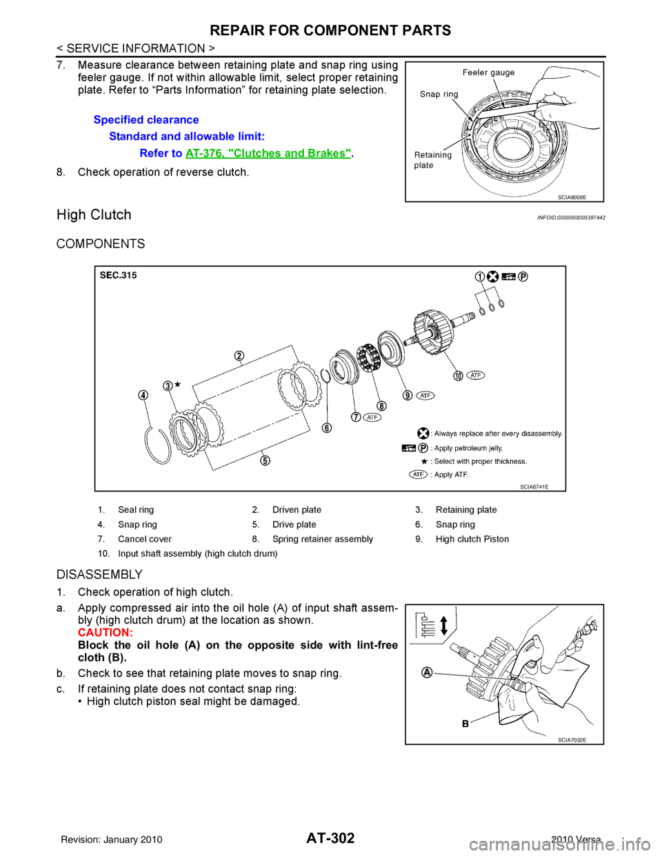
7. Measure clearance between retaining plate and snap ring usingfeeler gauge. If not within allowable limit, select proper retaining
plate. Refer to “Parts Information” for retaining plate selection.
8. Check operation of reverse clutch.
High ClutchINFOID:0000000005397442
COMPONENTS
DISASSEMBLY
1. Check operation of high clutch.
a. Apply compressed air into the oil hole (A) of input shaft assem- bly (high clutch drum) at the location as shown.
CAUTION:
Block the oil hole (A) on the opposite side with lint-free
cloth (B).
b. Check to see that retaining plate moves to snap ring.
c. If retaining plate does not contact snap ring: • High clutch piston seal might be damaged.Specified clearance
Standard and allowable limit: Refer to AT-376, "
Clutches and Brakes".
SCIA8009E
1. Seal ring 2. Driven plate 3. Retaining plate
4. Snap ring 5. Drive plate 6. Snap ring
7. Cancel cover 8. Spring retainer assembly 9. High clutch Piston
10. Input shaft assembly (high clutch drum)
SCIA6741E
SCIA7032E
Revision: January 20102010 Versa
Page 321 of 3745
AT-304
< SERVICE INFORMATION >
REPAIR FOR COMPONENT PARTS
INSPECTION
High Clutch Snap Ring
Check for deformation, fatigue or damage. Replace if necessary.
High Clutch Drive Plates
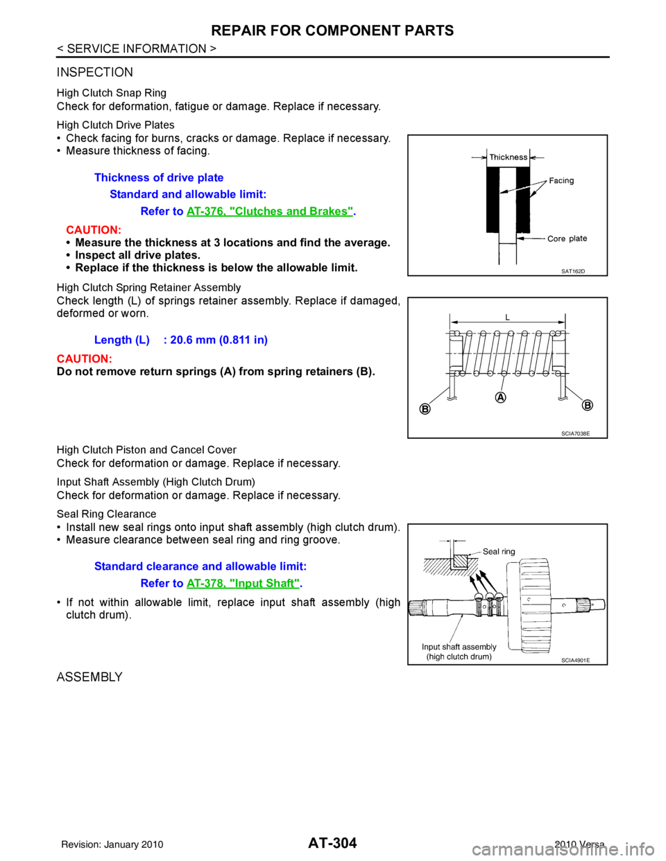
• Check facing for burns, cracks or damage. Replace if necessary.
• Measure thickness of facing.CAUTION:
• Measure the thickness at 3 locations and find the average.
• Inspect all drive plates.
• Replace if the thickness is below the allowable limit.
High Clutch Spring Retainer Assembly
Check length (L) of springs retainer assembly. Replace if damaged,
deformed or worn.
CAUTION:
Do not remove return springs (A ) from spring retainers (B).
High Clutch Piston and Cancel Cover
Check for deformation or damage. Replace if necessary.
Input Shaft Assembly (High Clutch Drum)
Check for deformation or damage. Replace if necessary.
Seal Ring Clearance
• Install new seal rings onto input shaft assembly (high clutch drum).
• Measure clearance between seal ring and ring groove.
• If not within allowable limit, replace input shaft assembly (high clutch drum).
ASSEMBLY
Thickness of drive plate
Standard and allowable limit: Refer to AT-376, "
Clutches and Brakes".
SAT162D
Length (L) : 20.6 mm (0.811 in)
SCIA7038E
Standard clearance and allowable limit:
Refer to AT-378, "
Input Shaft".
SCIA4901E
Revision: January 20102010 Versa
Page 323 of 3745
AT-306
< SERVICE INFORMATION >
REPAIR FOR COMPONENT PARTS
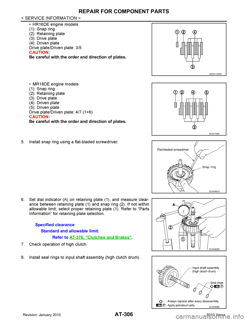
• HR16DE engine models
(1): Snap ring
(2): Retaining plate
(3): Drive plate
(4): Driven plate
Drive plate/Driven plate: 3/5
CAUTION:
Be careful with the order and direction of plates.
• MR18DE engine models
(1): Snap ring
(2): Retaining plate
(3): Drive plate
(4): Driven plate
(5): Driven plate
Drive plate/Driven plate: 4/7 (1+6)
CAUTION:
Be careful with the orde r and direction of plates.
5. Install snap ring using a flat-bladed screwdriver.
6. Set dial indicator (A) on retaining plate (1), and measure clear- ance between retaining plate (1) and snap ring (2). If not within
allowable limit, select proper retaining plate (1). Refer to “Parts
Information” for retaining plate selection.
7. Check operation of high clutch.
8. Install seal rings to input shaft assembly (high clutch drum).
JSDIA1108ZZ
SCIA7703E
SCIA4891E
Specified clearance Standard and allowable limit: Refer to AT-376, "
Clutches and Brakes".
SCIA5858E
SCIA4890E
Revision: January 20102010 Versa
Page 327 of 3745
AT-310
< SERVICE INFORMATION >
REPAIR FOR COMPONENT PARTS
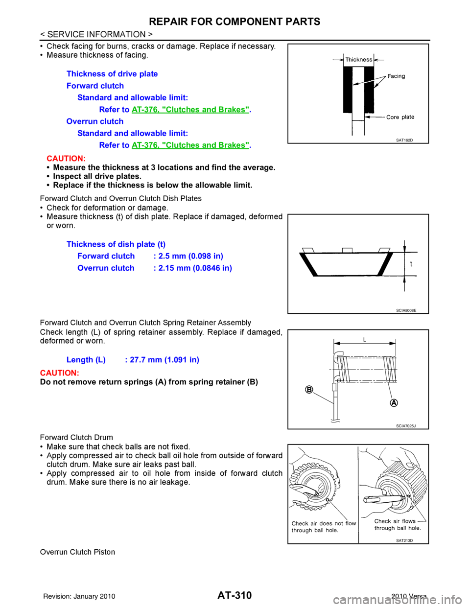
• Check facing for burns, cracks or damage. Replace if necessary.
• Measure thickness of facing.CAUTION:
• Measure the thickness at 3 locations and find the average.
• Inspect all drive plates.
• Replace if the thickness is below the allowable limit.
Forward Clutch and Overrun Clutch Dish Plates
• Check for deformation or damage.
• Measure thickness (t) of dish pl ate. Replace if damaged, deformed
or worn.
Forward Clutch and Overrun Clutch Spring Retainer Assembly
Check length (L) of spring retainer assembly. Replace if damaged,
deformed or worn.
CAUTION:
Do not remove return springs (A ) from spring retainer (B)
Forward Clutch Drum
• Make sure that check balls are not fixed.
• Apply compressed air to check ball oil hole from outside of forward
clutch drum. Make sure air leaks past ball.
• Apply compressed air to oil hole from inside of forward clutch drum. Make sure there is no air leakage.
Overrun Clutch Piston
Thickness of drive plate
Forward clutch
Standard and allowable limit: Refer to AT-376, "
Clutches and Brakes".
Overrun clutch Standard and allowable limit: Refer to AT-376, "
Clutches and Brakes".SAT162D
Thickness of dish plate (t)
Forward clutch : 2.5 mm (0.098 in)
Overrun clutch : 2.15 mm (0.0846 in)
SCIA8008E
Length (L) : 27.7 mm (1.091 in)
SCIA7025J
SAT213D
Revision: January 20102010 Versa
Page 849 of 3745

BR-1
BRAKES
C
DE
G H
I
J
K L
M
SECTION BR
A
B
BR
N
O P
CONTENTS
BRAKE SYSTEM
SERVICE INFORMATION .. ..........................2
PRECAUTIONS .............................................. .....2
Precaution for Supplemental Restraint System
(SRS) "AIR BAG" and "SEAT BELT PRE-TEN-
SIONER" ............................................................. ......
2
Precaution Necessary for Steering Wheel Rota-
tion After Battery Disconnect ............................... ......
2
Precaution for Brake System ....................................3
PREPARATION ...................................................4
Special Service Tool ........................................... ......4
Commercial Service Tool ..........................................4
NOISE, VIBRATION AND HARSHNESS
(NVH) TROUBLESHOOTING .............................
5
NVH Troubleshooting Chart ................................ ......5
BRAKE PEDAL .............................................. .....6
Inspection and Adjustment .................................. ......6
Removal and Installation ...........................................7
BRAKE FLUID ................................................ .....9
On Board Inspection ........................................... ......9
Drain and Refill ..........................................................9
Bleeding Brake System .............................................9
BRAKE TUBE AND HOSE ................................11
Hydraulic Circuit .................................................. ....11
Front Brake Tube and Hose ....................................12
Rear Brake Tube and Hose ....................................12
Inspection After Installation .....................................13
DUAL PROPORTIONING VALVE .....................14
Removal and Installation .........................................14
Inspection ............................................................ ....14
BRAKE MASTER CYLINDER ........................ ....15
On-Board Inspection ........................................... ....15
Removal and Installation ..................................... ....15
Disassembly and Assembly .....................................16
BRAKE BOOSTER ...........................................20
On Board Inspection ............................................ ....20
Removal and Installation .........................................21
VACUUM LINES ...............................................23
Component ..............................................................23
Removal and Installation .........................................23
Inspection ................................................................23
FRONT DISC BRAKE .......................................25
On Board Inspection ............................................ ....25
Component ..............................................................25
Removal and Installation of Brake Pad ...................26
Removal and Installation of Brake Caliper Assem-
bly ........................................................................ ....
30
Disassembly and Assembly of Brake Caliper As-
sembly .....................................................................
31
Brake Burnishing Procedure ....................................34
REAR DRUM BRAKE .......................................35
Component .......................................................... ....35
Removal and Installation of Drum Brake Assembly
....
36
Removal and Installation of Wheel Cylinder ............39
Disassembly and Assembly of Wheel Cylinder .......39
SERVICE DATA AND SPECIFICATIONS
(SDS) .................................................................
40
General Specification ..............................................40
Brake Pedal .............................................................41
Check Valve ............................................................41
Brake Booster ..........................................................42
Front Disc Brake ......................................................42
Rear Drum Brake .....................................................42
Revision: January 20102010 Versa