2010 NISSAN TIIDA throttle control
[x] Cancel search: throttle controlPage 192 of 3745
TR SW, OD SW AND CLOSED THROTTLE, WIDE OPEN THROTTLE POSITION
SIGNAL CIRCUIT
AT-175
< SERVICE INFORMATION >
DE
F
G H
I
J
K L
M A
B
AT
N
O P
11 .PERFORM SELF-DIAGNOSIS
Without CONSULT-III
Perform self-diagnosis. Refer to AT-82, "
Diagnosis Procedure without CONSULT-III".
OK or NG
OK >> INSPECTION END
NG − 1 >> Self-diagnosis does not activate: GO TO 12.
NG − 2 >> DTC is displayed: Check the malfunctioning system. Refer to AT-82, "
Diagnosis Procedure with-
out CONSULT-III".
12.CHECK TCM
1. Check TCM input/output signal. Refer to AT-75, "
TCM Terminal and Reference Value".
2. If NG, recheck TCM pin terminals for dam age or loose connection with harness connector.
OK or NG
OK >> INSPECTION END
NG >> Repair or replace damaged parts.
Component InspectionINFOID:0000000005397388
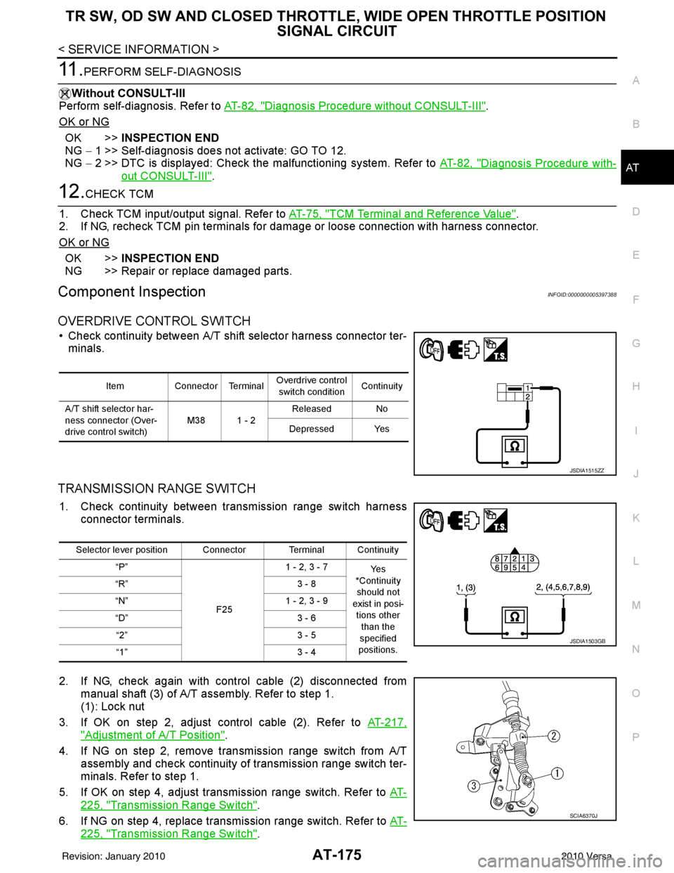
OVERDRIVE CONTROL SWITCH
• Check continuity between A/T shift selector harness connector ter- minals.
TRANSMISSION RANGE SWITCH
1. Check continuity between transmission range switch harness connector terminals.
2. If NG, check again with control cable (2) disconnected from manual shaft (3) of A/T assembly. Refer to step 1.
(1): Lock nut
3. If OK on step 2, adjust control cable (2). Refer to AT-217,
"Adjustment of A/T Position".
4. If NG on step 2, remove transmission range switch from A/T assembly and check continuity of transmission range switch ter-
minals. Refer to step 1.
5. If OK on step 4, adjust transmission range switch. Refer to AT-
225, "Transmission Range Switch".
6. If NG on step 4, replace transmission range switch. Refer to AT-
225, "Transmission Range Switch".
ItemConnector Terminal Overdrive control
switch condition Continuity
A/T shift selector har-
ness connector (Over-
drive control switch) M38 1 - 2Released No
Depressed Yes
JSDIA1515ZZ
Selector lever position Connector Terminal Continuity “P”
F251 - 2, 3 - 7
Ye s
*Continuity
should not
exist in posi- tions other
than the
specified
positions.
“R”
3 - 8
“N” 1 - 2, 3 - 9
“D” 3 - 6
“2” 3 - 5
“1” 3 - 4
JSDIA1503GB
SCIA6370J
Revision: January 20102010 Versa
Page 222 of 3745
TROUBLE DIAGNOSIS FOR SYMPTOMSAT-205
< SERVICE INFORMATION >
DE
F
G H
I
J
K L
M A
B
AT
N
O P
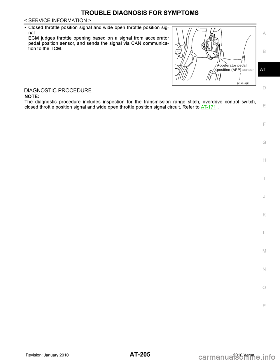
• Closed throttle position signal and wide open throttle position sig- nal
ECM judges throttle opening based on a signal from accelerator
pedal position sensor, and sends the signal via CAN communica-
tion to the TCM.
DIAGNOSTIC PROCEDURE
NOTE:
The diagnostic procedure includes inspection for the tr ansmission range stitch, overdrive control switch,
closed throttle position signal and wide open throttle position signal circuit. Refer to AT-171
.
SCIA7143E
Revision: January 20102010 Versa
Page 934 of 3745
![NISSAN TIIDA 2010 Service Repair Manual BRC-44
< SERVICE INFORMATION >[VDC/TCS/ABS]
SYSTEM DESCRIPTION
TCS Function
INFOID:0000000005612145
• Spinning of the drive wheels is detected by the A BS/TCS/VDC control unit using inputs from the](/manual-img/5/57397/w960_57397-933.png "NISSAN TIIDA 2010 Service Repair Manual BRC-44
< SERVICE INFORMATION >[VDC/TCS/ABS]
SYSTEM DESCRIPTION
TCS Function
INFOID:0000000005612145
• Spinning of the drive wheels is detected by the A BS/TCS/VDC control unit using inputs from the")
BRC-44
< SERVICE INFORMATION >[VDC/TCS/ABS]
SYSTEM DESCRIPTION
TCS Function
INFOID:0000000005612145
• Spinning of the drive wheels is detected by the A BS/TCS/VDC control unit using inputs from the wheel
speed sensors. If wheel spin occurs, the drive wheel right and left brake fluid pressure control and engine
fuel cut are conducted while the throttle value is restricted to reduce the engine torque and decrease the
amount of wheel spin. In addition, the throttle openi ng is controlled to achieve the optimum engine torque.
• Depending on road condition, the vehicle may have a sluggish feel. This is normal, because optimum trac- tion has the highest priority during TCS operation.
• TCS may be activated during sudden vehicle acceleration, wide open throttle acceleration, sudden transmis- sion shifts or when the vehicle is driven on a road with a varying surface friction coefficient.
• The SLIP indicator lamp flashes to inform the driver of TCS operation.
VDC FunctionINFOID:0000000005612146
• In addition to the ABS/TCS function, the driver steering amount and brake operation amount are detected
from the steering angle sensor, and the vehicle's drivi ng status (amount of under steering/over steering) is
determined using inputs from the yaw rate/side/decel G sensor, wheel speed sensors, etc. and this informa-
tion is used to improve vehicle stability by cont rolling the braking and engine torque application to the
wheels.
• The SLIP indicator lamp flashes to inform the driver of VDC operation.
• During VDC operation, the vehicle body and brake pedal may vibrate lightly and a mechanical noise may be
heard. This is normal.
• The ABS warning lamp, VDC OFF indicator lamp and SLIP indicator lamp may turn on when the vehicle is
subject to strong shaking or large vibration, such as when the vehicle is on a turn table or a ship while the
engine is running or steep slope. In this case, rest art the engine on a normal road and if the ABS warning
lamp, VDC OFF indicator lamp and SLIP indicator lamp turn off, there is no problem.
Wheel SensorsINFOID:0000000005612147
The front sensor units consist of a gear-shaped sensor rotor and a
sensor element. The element contains a magnet around which a coil
is wound. The front wheel sensors are installed on the front of the
wheel knuckles. As the wheel rotates, the sensor generates a
square-wave signal. The frequency in creases as the wheel speed
increases.
The rear sensor units consist of w heel hubs with a series of internal
magnets and a sensor element. The rear wheel sensors are installed
on the inner side of the wheel knuckles. As the wheel rotates, the
sensor generates a square-wave signal. The frequency increases as
the wheel speed increases.
Fail-Safe FunctionINFOID:0000000005612148
ABS/EBD SYSTEM
In case of an electrical malfunction with the ABS, t he ABS warning lamp, VDC OFF indicator lamp and SLIP
indicator lamp will turn on. In case of an electrical malfunction with the EBD system, the BRAKE warning lamp,
ABS warning lamp, VDC OFF indicator lamp and SLIP indicator lamp will turn on.
LBR333
WFIA0033E
Revision: January 20102010 Versa
Page 954 of 3745
![NISSAN TIIDA 2010 Service Repair Manual BRC-64
< SERVICE INFORMATION >[VDC/TCS/ABS]
TROUBLE DIAGNOSIS
FR LH OUT SOL
(On/Off)—
×× Front LH OUT ABS solenoid (On/Off) status is dis-
played.
RR RH IN SOL
(On/Off) —
×× Rear RH IN ABS sol](/manual-img/5/57397/w960_57397-953.png "NISSAN TIIDA 2010 Service Repair Manual BRC-64
< SERVICE INFORMATION >[VDC/TCS/ABS]
TROUBLE DIAGNOSIS
FR LH OUT SOL
(On/Off)—
×× Front LH OUT ABS solenoid (On/Off) status is dis-
played.
RR RH IN SOL
(On/Off) —
×× Rear RH IN ABS sol")
BRC-64
< SERVICE INFORMATION >[VDC/TCS/ABS]
TROUBLE DIAGNOSIS
FR LH OUT SOL
(On/Off)—
×× Front LH OUT ABS solenoid (On/Off) status is dis-
played.
RR RH IN SOL
(On/Off) —
×× Rear RH IN ABS solenoid (On/Off) status is dis-
played.
RR RH OUT SOL
(On/Off) —
×× Rear RH OUT ABS solenoid (On/Off) status is dis-
played.
RR LH IN SOL
(On/Off) —
×× Rear LH IN ABS solenoid (On/Off) status is dis-
played.
RR LH OUT SOL
(On/Off) —
×× Rear LH OUT ABS solenoid (On/Off) status is dis-
played.
STOP LAMP SW
(On/Off) ×××
Stop lamp switch (On/Off) status is displayed.
MOTOR RELAY
(On/Off) —
×× ABS motor relay signal (On/Off) status is dis-
played.
ACTUATOR RLY
(On/Off) —
×× ABS actuator relay signal (On/Off) status is dis-
played.
ABS WARN LAMP
(On/Off) —
×× ABS warning lamp (On/Off) status is displayed.
OFF LAMP
(On/Off) —
×× VDC OFF lamp (On/Off) status is displayed.
OFF SW
(On/Off) ×××
VDC OFF switch (On/Off) status is displayed.
SLIP LAMP
(On/Off) —
×× SLIP indicator lamp (On/Off) status is displayed.
BATTERY VOLT
(V) ××× Voltage (V) supplied to ABS actuator and electric
unit (control unit) is displayed.
GEAR
(1, 2, 3, 4) ××× A/T gear position (1, 2, 3, 4) determined by TCM
is displayed.
YAW RATE SEN
(d/s) ×××
Yaw rate (d/s) detected by yaw rate sensor is dis-
played.
ACCEL POS SIG
(%) ×
— ×Throttle valve open/close (%) status judged by
CAN communication signal is displayed.
SIDE G-SENSOR
(m/s
2) ×
— ×Lateral acceleration (m/s
2) detected by side G
sensor is displayed.
STR ANGLE SIG
(deg) ×
— ×Steering angle (deg) detected by steering angle
sensor is displayed.
PRESS SENSOR
(bar) ×
— ×Brake fluid pressure detected by pressure sensor
is displayed.
EBD SIGNAL
(On/Off) ——
×EBD operation (On/Off) status is displayed.
ABS SIGNAL
(On/Off) ——
×ABS operation (On/Off) status is displayed.
TCS SIGNAL
(On/Off) ——
×TCS operation (On/Off) status is displayed.
VDC SIGNAL
(On/Off) ——
×VDC operation (On/Off) status is displayed.
EBD FAIL SIG
(On/Off) ——
×EBD fail signal (On/Off) status is displayed.
ABS FAIL SIG
(On/Off) ——
×ABS fail signal (On/Off) status is displayed.
TCS FAIL SIG
(On/Off) ——
×TCS fail signal (On/Off) status is displayed.
VDC FAIL SIG
(On/Off) ——
×VDC fail signal (On/Off) status is displayed.
Revision: January 20102010 Versa
Page 992 of 3745
![NISSAN TIIDA 2010 Service Repair Manual CO-10
< FUNCTION DIAGNOSIS >[HR16DE]
DESCRIPTION
FUNCTION DIAGNOSIS
DESCRIPTION
Engine Cooling SystemINFOID:0000000005398181
AWBIA0155ZZ
1. Cylinder head
2. Cylinder block3. Water pump
4. Thermostat 5](/manual-img/5/57397/w960_57397-991.png "NISSAN TIIDA 2010 Service Repair Manual CO-10
< FUNCTION DIAGNOSIS >[HR16DE]
DESCRIPTION
FUNCTION DIAGNOSIS
DESCRIPTION
Engine Cooling SystemINFOID:0000000005398181
AWBIA0155ZZ
1. Cylinder head
2. Cylinder block3. Water pump
4. Thermostat 5")
CO-10
< FUNCTION DIAGNOSIS >[HR16DE]
DESCRIPTION
FUNCTION DIAGNOSIS
DESCRIPTION
Engine Cooling SystemINFOID:0000000005398181
AWBIA0155ZZ
1. Cylinder head
2. Cylinder block3. Water pump
4. Thermostat 5. Water inlet6. Water bypass
7. Water outlet A. From radiatorB. To radiator
C. From electric throttle control actuator D. From heater E. To heater
F. To electric throttle control actuator Thermostat openThermostat closed
Revision: January 20102010 Versa
Page 993 of 3745
![NISSAN TIIDA 2010 Service Repair Manual DESCRIPTIONCO-11
< FUNCTION DIAGNOSIS > [HR16DE]
C
D
E
F
G H
I
J
K L
M A
CO
NP
O
Engine Cooling System SchematicINFOID:0000000005398182
AWBIA0784ZZ
1. Reservoir tank
2. Radiator3. Water inlet
4. Therm](/manual-img/5/57397/w960_57397-992.png "NISSAN TIIDA 2010 Service Repair Manual DESCRIPTIONCO-11
< FUNCTION DIAGNOSIS > [HR16DE]
C
D
E
F
G H
I
J
K L
M A
CO
NP
O
Engine Cooling System SchematicINFOID:0000000005398182
AWBIA0784ZZ
1. Reservoir tank
2. Radiator3. Water inlet
4. Therm")
DESCRIPTIONCO-11
< FUNCTION DIAGNOSIS > [HR16DE]
C
D
E
F
G H
I
J
K L
M A
CO
NP
O
Engine Cooling System SchematicINFOID:0000000005398182
AWBIA0784ZZ
1. Reservoir tank
2. Radiator3. Water inlet
4. Thermostat 5. Water bypass6. Water jacket
7. Water pump 8. Cylinder block9. Cylinder head
10. Water outlet 11. Electric throttle control actuator 12. Heater
A. Thermostat open B. Thermostat closedC. Constant
Revision: January 20102010 Versa
Page 1007 of 3745
![NISSAN TIIDA 2010 Service Repair Manual WATER OUTLETCO-25
< ON-VEHICLE REPAIR > [HR16DE]
C
D
E
F
G H
I
J
K L
M A
CO
NP
O
WATER OUTLET
Exploded ViewINFOID:0000000005398198
Removal and InstallationINFOID:0000000005398199
REMOVAL
1. Drain engi](/manual-img/5/57397/w960_57397-1006.png "NISSAN TIIDA 2010 Service Repair Manual WATER OUTLETCO-25
< ON-VEHICLE REPAIR > [HR16DE]
C
D
E
F
G H
I
J
K L
M A
CO
NP
O
WATER OUTLET
Exploded ViewINFOID:0000000005398198
Removal and InstallationINFOID:0000000005398199
REMOVAL
1. Drain engi")
WATER OUTLETCO-25
< ON-VEHICLE REPAIR > [HR16DE]
C
D
E
F
G H
I
J
K L
M A
CO
NP
O
WATER OUTLET
Exploded ViewINFOID:0000000005398198
Removal and InstallationINFOID:0000000005398199
REMOVAL
1. Drain engine coolant from radiator. Refer to
CO-12, "Changing Engine Coolant".
CAUTION:
• Perform this step when engine is cold.
• Never spill engine coolant on drive belt.
2. Remove air duct and air duct (inlet). Refer to EM-26, "
Exploded View".
3. Remove battery and battery tray. Refer to SC-7, "
Removal and Installation".
4. Remove reservoir tank. Refer to CO-17, "
Component".
5. Disconnect radiator hose (upper). Refer to CO-17, "
Component".
6. Disconnect harness connector from engine coolant temperature sensor and block heater, if equipped.
7. Remove electric throttle control actuator water hoses.
8. Remove heater hoses.
9. Remove water outlet.
1. Engine coolant temperature sensor 2. Washer 3. Gasket
4. Radiator hose (upper) 5. Water outlet 6. Heater hose
7. Heater hose 8. Water hose 9. Water hose
10. Block heater (Canada only)
A. To electric throttle control actuator B. To heater core C. To radiator
: Engine front
AWBIA0788GB
Revision: January 20102010 Versa
Page 1030 of 3745
![NISSAN TIIDA 2010 Service Repair Manual CO-48
< SERVICE INFORMATION >[MR18DE]
WATER OUTLET AND WATER CONTROL VALVE
WATER OUTLET AND WATER CONTROL VALVE
ComponentINFOID:0000000005398226
Removal and InstallationINFOID:0000000005398227
REMOVAL](/manual-img/5/57397/w960_57397-1029.png "NISSAN TIIDA 2010 Service Repair Manual CO-48
< SERVICE INFORMATION >[MR18DE]
WATER OUTLET AND WATER CONTROL VALVE
WATER OUTLET AND WATER CONTROL VALVE
ComponentINFOID:0000000005398226
Removal and InstallationINFOID:0000000005398227
REMOVAL")
CO-48
< SERVICE INFORMATION >[MR18DE]
WATER OUTLET AND WATER CONTROL VALVE
WATER OUTLET AND WATER CONTROL VALVE
ComponentINFOID:0000000005398226
Removal and InstallationINFOID:0000000005398227
REMOVAL
1. Drain engine coolant from radiator. Refer to
CO-36, "Changing Engine Coolant".
CAUTION:
• Perform this step when engine is cold.
• Never spill engine coolant on drive belt.
2. Remove battery and battery tray. Refer to SC-7, "
Removal and Installation".
3. Remove air cleaner and air duct. Refer to EM-135, "
Component".
4. Remove radiator hose (lower) from engine. Refer to CO-40, "
Component".
5. Remove heater hoses and water hoses.
6. Remove water outlet.
7. Remove water control valve.
8. Remove engine coolant temperature sensor from the water outlet, if necessary.
CAUTION:
• Handle carefully to avoid any shock to engine coolant temperature sensor.
• Replace the gasket with a new one.
INSPECTION AFTER REMOVAL
1. Engine coolant temperature sensor 2. Rubber ring 3. Water control valve
4. Gasket 5. Water hose 6. Gasket
7. Water hose 8. Water outlet 9. Heater hose
10. Heater hose 11. Radiator hose (upper) Front
A. To heater B. To electric throttle control actuator C. To radiator
PBIC4699E
Revision: January 20102010 Versa