2010 NISSAN TIIDA ignition
[x] Cancel search: ignitionPage 662 of 3745
INTELLIGENT KEY SYSTEMBL-153
< SERVICE INFORMATION >
C
DE
F
G H
J
K L
M A
B
BL
N
O P
OK >> Check condition of harness and connector.
NG >> Repair or replace harness.
CVT or A/T Shift Se lector (Park Position Switch) CheckINFOID:0000000005396632
1.CHECK CVT OR A/T SHIFT SELECTOR (PARK POSITION SWITCH) INPUT SIGNAL
1. Turn ignition switch OFF.
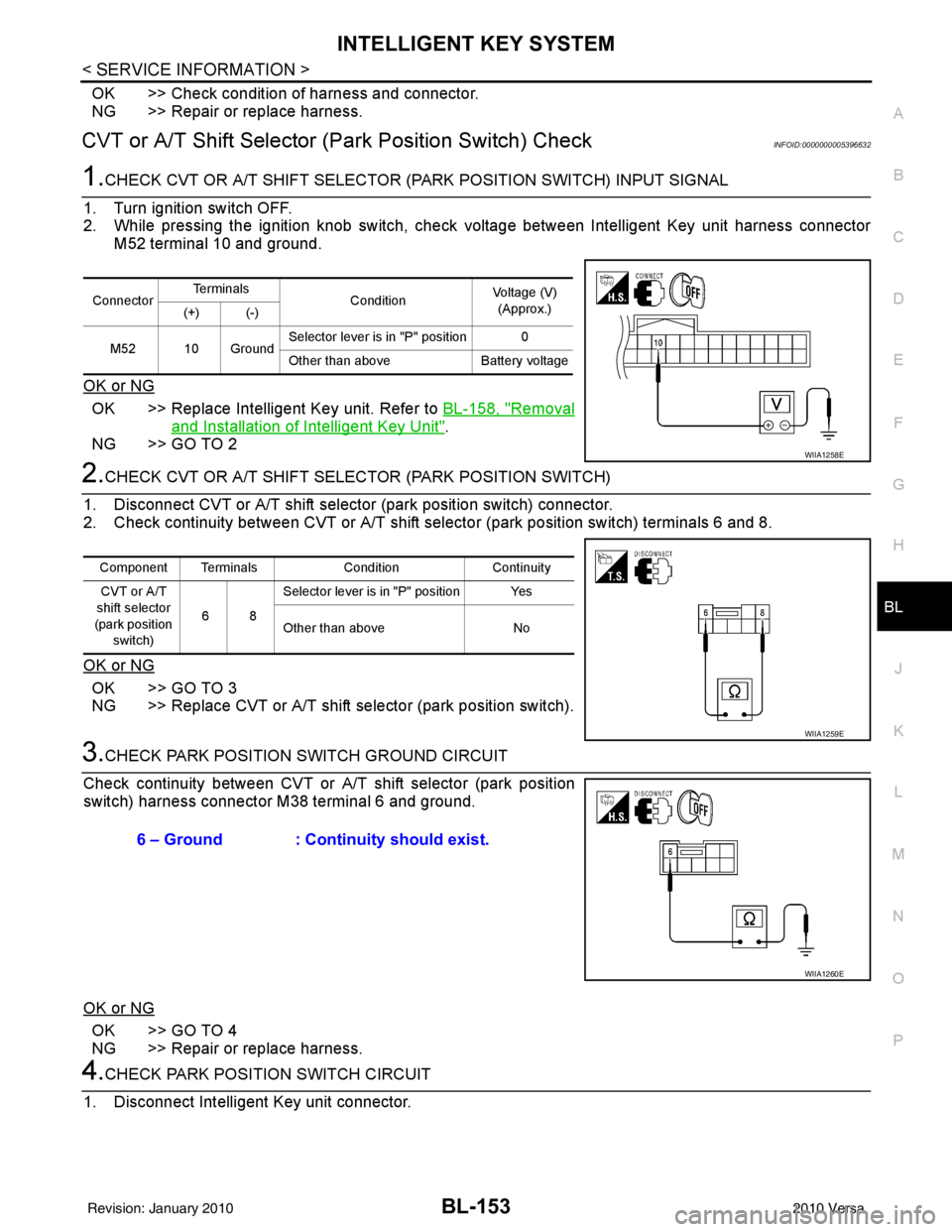
2. While pressing the ignition knob switch, check voltage between Intelligent Key unit harness connector M52 terminal 10 and ground.
OK or NG
OK >> Replace Intelligent Key unit. Refer to BL-158, "Removal
and Installation of Intelligent Key Unit".
NG >> GO TO 2
2.CHECK CVT OR A/T SHIFT SELECTOR (PARK POSITION SWITCH)
1. Disconnect CVT or A/T shift select or (park position switch) connector.
2. Check continuity between CVT or A/T shift selector (park position switch) terminals 6 and 8.
OK or NG
OK >> GO TO 3
NG >> Replace CVT or A/T shift selector (park position switch).
3.CHECK PARK POSITION SWITCH GROUND CIRCUIT
Check continuity between CVT or A/T shift selector (park position
switch) harness connector M38 terminal 6 and ground.
OK or NG
OK >> GO TO 4
NG >> Repair or replace harness.
4.CHECK PARK POSITION SWITCH CIRCUIT
1. Disconnect Intelligent Key unit connector.
Connector Te r m i n a l s
ConditionVoltage (V)
(Approx.)
(+) (-)
M52 10 Ground Selector lever is in "P" position 0
Other than above
Battery voltage
WIIA1258E
Component Terminals ConditionContinuity
CVT or A/T
shift selector
(park position switch) 68Selector lever is in "P" position Yes
Other than above
No
WIIA1259E
6 – Ground : Continuity should exist.
WIIA1260E
Revision: January 20102010 Versa
Page 663 of 3745
BL-154
< SERVICE INFORMATION >
INTELLIGENT KEY SYSTEM
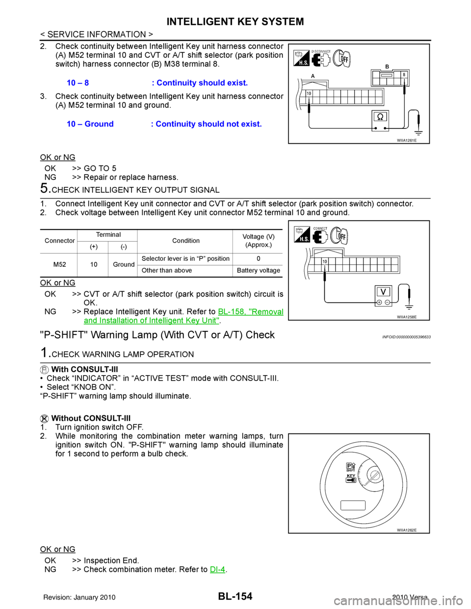
2. Check continuity between Intelligent Key unit harness connector
(A) M52 terminal 10 and CVT or A/T shift selector (park position
switch) harness connector (B) M38 terminal 8.
3. Check continuity between Inte lligent Key unit harness connector
(A) M52 terminal 10 and ground.
OK or NG
OK >> GO TO 5
NG >> Repair or replace harness.
5.CHECK INTELLIGENT KEY OUTPUT SIGNAL
1. Connect Intelligent Key unit connector and CVT or A/T shift selector (park position switch) connector.
2. Check voltage between Intelligent Key unit connector M52 terminal 10 and ground.
OK or NG
OK >> CVT or A/T shift selector (park position switch) circuit is
OK.
NG >> Replace Intelligent Key unit. Refer to BL-158, "
Removal
and Installation of Intelligent Key Unit".
"P-SHIFT" Warning Lamp (With CVT or A/T) CheckINFOID:0000000005396633
1.CHECK WARNING LAMP OPERATION
With CONSULT-III
• Check “INDICATOR” in “ACTIVE TEST” mode with CONSULT-III.
• Select “KNOB ON”.
“P-SHIFT” warning lamp should illuminate.
Without CONSULT-III
1. Turn ignition switch OFF.
2. While monitoring the combination meter warning lamps, turn
ignition switch ON. "P-SHIFT" warning lamp should illuminate
for 1 second to perform a bulb check.
OK or NG
OK >> Inspection End.
NG >> Check combination meter. Refer to DI-4
.
10 – 8 : Continuity should exist.
10 – Ground : Continuity should not exist.
WIIA1261E
Connector
Te r m i n a l
ConditionVoltage (V)
(Approx.)
(+) (-)
M52 10 Ground Selector lever is in “P” position 0
Other than above
Battery voltage
WIIA1258E
WIIA1262E
Revision: January 20102010 Versa
Page 664 of 3745
INTELLIGENT KEY SYSTEMBL-155
< SERVICE INFORMATION >
C
DE
F
G H
J
K L
M A
B
BL
N
O P
"LOCK" Warning Lamp (With M/T) CheckINFOID:0000000005396634
1.CHECK WARNING LAMP OPERATION
With CONSULT-III
• Check “INDICATOR” in “ACTIVE TEST” mode with CONSULT-III.
• Select “KNOB ON”.
“LOCK” warning lamp should illuminate.
Without CONSULT-III
1. Turn ignition switch OFF.
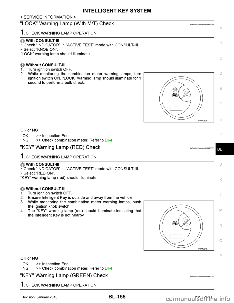
2. While monitoring the combination meter warning lamps, turn
ignition switch ON. "LOCK" warning lamp should illuminate for 1
second to perform a bulb check.
OK or NG
OK >> Inspection End.
NG >> Check combination meter. Refer to DI-4
.
"KEY" Warning Lamp (RED) CheckINFOID:0000000005396635
1.CHECK WARNING LAMP OPERATION
With CONSULT-III
• Check “INDICATOR” in “ACTIVE TEST” mode with CONSULT-III.
• Select “RED ON”.
“KEY” warning lamp (red) should illuminate.
Without CONSULT-III
1. Turn ignition switch OFF.
2. Ensure Intelligent Key is outside and away from the vehicle.
3. While monitoring the combination meter warning lamps, push the ignition knob switch.
4. The "KEY" warning lamp (red) should illuminate indicating that the Intelligent Key is not nearby.
OK or NG
OK >> Inspection End.
NG >> Check combination meter. Refer to DI-4
.
"KEY" Warning Lamp (GREEN) CheckINFOID:0000000005396636
1.CHECK WARNING LAMP OPERATION
WIIA1263E
WIIA1264E
Revision: January 20102010 Versa
Page 665 of 3745
BL-156
< SERVICE INFORMATION >
INTELLIGENT KEY SYSTEM
With CONSULT-III
• Check “INDICATOR” in “ACTIVE TEST” mode with CONSULT-III.
• Select “BLUE ON”.
“KEY” warning lamp (green) should illuminate.
Without CONSULT-III
1. Turn ignition switch OFF.
2. Ensure Intelligent Key is in your possession inside the vehicle.
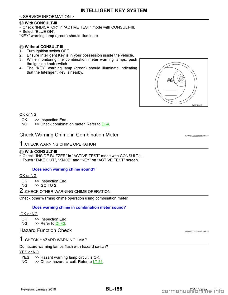
3. While monitoring the combination meter warning lamps, push the ignition knob switch.
4. The "KEY" warning lamp (green) should illuminate indicating that the Intelligent Key is nearby.
OK or NG
OK >> Inspection End.
NG >> Check combination meter. Refer to DI-4
.
Check Warning Chime in Combination MeterINFOID:0000000005396637
1.CHECK WARNING CHIME OPERATION
With CONSULT-III
• Check “INSIDE BUZZER” in “ACTIVE TEST” mode with CONSULT-III.
• Touch “TAKE OUT”, “KNOB” and “KEY” on “ACTIVE TEST” screen.
OK or NG
OK >> Inspection End.
NG >> GO TO 2.
2.CHECK OTHER WARNING CHIME OPERATION
Check other warning chime operation using combination meter.
OK or NG
OK >> Inspection End.
NG >> Refer to DI-43
.
Hazard Function CheckINFOID:0000000005396638
1.CHECK HAZARD WARNING LAMP
Do hazard warning lamps flash with hazard switch?
YES or NO
YES >> Hazard warning lamp circuit is OK.
NO >> Check hazard circuit. Refer to LT- 5 1
.
WIIA1264E
Does each warning chime sound?
Does warning chime in combination meter sound?
Revision: January 20102010 Versa
Page 666 of 3745
INTELLIGENT KEY SYSTEMBL-157
< SERVICE INFORMATION >
C
DE
F
G H
J
K L
M A
B
BL
N
O P
Horn Function CheckINFOID:0000000005396639
First perform the “SELF-DIAG RESULTS” of “BCM” with CONSULT-III, then perform the trouble diag-
nosis of malfunction system indicated in “SELF-DIAG RESULTS” of “BCM”. Refer to BCS-18, "
CAN
Communication Inspection Using CONSULT-III (Self-Diagnosis)".
1.CHECK HORN OPERATION
Check if horn sounds with horn switch.
Does horn operate?
Yes >> GO TO 2
No >> Check horn circuit. Refer to WW-39
.
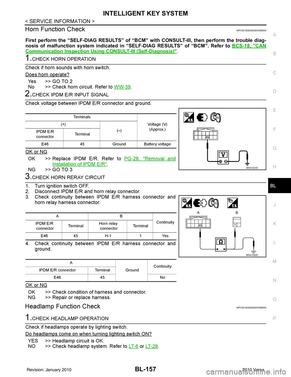
2.CHECK IPDM E/R INPUT SIGNAL
Check voltage between IPDM E/R connector and ground.
OK or NG
OK >> Replace IPDM E/R. Refer to PG-28, "Removal and
Installation of IPDM E/R".
NG >> GO TO 3
3.CHECK HORN RERAY CIRCUIT
1. Turn ignition switch OFF.
2. Disconnect IPDM E/R and horn relay connector.
3. Check continuity between IPDM E/R harness connector and horn relay harness connector.
4. Check continuity between IPDM E/R harness connector and ground.
OK or NG
OK >> Check condition of harness and connector.
NG >> Repair or replace harness.
Headlamp Function CheckINFOID:0000000005396640
1.CHECK HEADLAMP OPERATION
Check if headlamps operate by lighting switch.
Do headlamps come on when turning lighting switch ON?
YES >> Headlamp circuit is OK.
NO >> Check headlamp system. Refer to LT- 6
or LT- 2 8.
Te r m i n a l s
Voltage (V)(Approx.)
(+)
(–)
IPDM E/R
connector Te r m i n a l
E46 45Ground Ba ttery voltage
WIIA1251E
AB
Continuity
IPDM E/R
connector Te r m i n a l
Horn relay
connector Te r m i n a l
E46 45H-1 1Yes
A GroundContinuity
IPDM E/R connector Terminal
E46 45 No
WIIA1252E
Revision: January 20102010 Versa
Page 684 of 3745
BACK DOOR LOCKBL-175
< SERVICE INFORMATION >
C
DE
F
G H
J
K L
M A
B
BL
N
O P
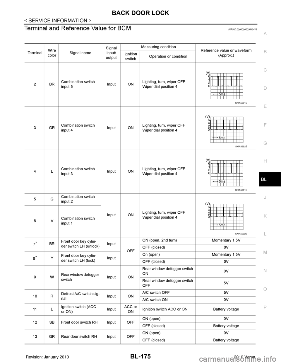
Terminal and Reference Value for BCMINFOID:0000000005612419
Te r m i n a l Wire
color Signal name Signal
input/
output Measuring condition
Reference value or waveform
(Approx.)
Ignition
switch Operation or condition
2BR Combination switch
input 5
Input ONLighting, turn, wiper OFF
Wiper dial position 4
3GR Combination switch
input 4 Input ONLighting, turn, wiper OFF
Wiper dial position 4
4L Combination switch
input 3
Input ONLighting, turn, wiper OFF
Wiper dial position 4
5G Combination switch
input 2
Input ONLighting, turn, wiper OFF
Wiper dial position 4
6V Combination switch
input 1
7
7BR Front door key cylin-
der switch LH (unlock) Input
OFFON (open, 2nd turn)
Momentary 1.5V
OFF (closed) 0V
8
7Y Front door key cylin-
der switch LH (lock) InputOn (open)
Momentary 1.5V
OFF (closed) 0V
9W Rear window defogger
switch Input ONRear window defogger switch
ON
0V
Rear window defogger switch
OFF 5V
10 R Defrost A/C switch sig-
nal
Input ONA/C switch OFF
5V
A/C switch ON 0V
11 L Ignition switch (ACC
or ON) InputACC or
ON Ignition switch ACC or ON
Battery voltage
12 SB Front door switch RH Input OFF ON (open)
0V
OFF (closed) Battery voltage
13 GR Rear door switch RH Input OFF ON (open)
0V
OFF (closed) Battery voltage
SKIA5291E
SKIA5292E
SKIA5291E
SKIA5292E
Revision: January 20102010 Versa
Page 685 of 3745
BL-176
< SERVICE INFORMATION >
BACK DOOR LOCK
15 WTire pressure warning
check connector
Input OFF
—5V
18 V Remote keyless entry
receiver (ground) Output OFF
—0V
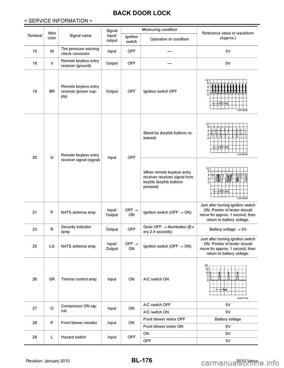
19 BR Remote keyless entry
receiver (power sup-
ply) Output OFF Ignition switch OFF
20 G Remote keyless entry
receiver signal (signal)
Input OFFStand-by (keyfob buttons re-
leased)
When remote keyless entry
receiver receives signal from
keyfob (keyfob buttons
pressed)
21 P NATS antenna amp. Input/
Output OFF
→
ON Ignition switch (OFF
→ ON)Just after turning ignition switch
ON: Pointer of tester should
move for approx. 1 second, then
return to battery voltage.
23 R Security indicator
lamp Output OFF
Goes OFF
→ illuminates (Ev-
ery 2.4 seconds) Battery voltage
→ 0V
25 LG NATS antenna amp. Input/
Output OFF
→
ON Ignition switch (OFF
→ ON)Just after turning ignition switch
ON: Pointer of tester should
move for approx. 1 second, then return to battery voltage.
26 GR Thermo control amp. Input ON A/C switch ON
27 O Compressor ON sig-
nal Input ONA/C switch OFF
5V
A/C switch ON 0V
28 P Front blower monitor Input ON Front blower motor OFF
Battery voltage
Front blower motor ON 0V
29 L Hazard switch Input OFFON
0V
OFF 5V
Te r m i n a l
Wire
color Signal name Signal
input/
output Measuring condition
Reference value or waveform
(Approx.)
Ignition
switch Operation or condition
LIIA1893E
LIIA1894E
LIIA1895E
ZJIA0719J
Revision: January 20102010 Versa
Page 686 of 3745
BACK DOOR LOCKBL-177
< SERVICE INFORMATION >
C
DE
F
G H
J
K L
M A
B
BL
N
O P
301LG Back door/trunk out-
put Output —Back door open (switch
closed)
0V
Back door closed (switch
open) 5V
30
3LG Back door opener
switch
Input —All doors locked (SW OFF)
Battery voltage
All doors unlocked (SW ON) 0V
30
4V Trunk lid opener
switch
Input —All doors locked (SW OFF)
Battery voltage
All doors unlocked (SW ON) 0V
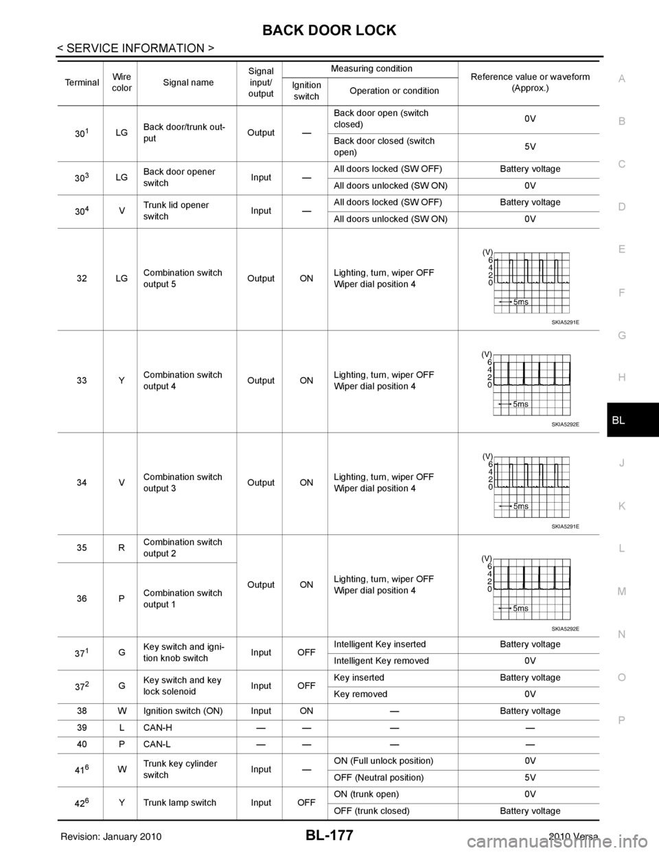
32 LG Combination switch
output 5 Output ONLighting, turn, wiper OFF
Wiper dial position 4
33 Y Combination switch
output 4 Output ON
Lighting, turn, wiper OFF
Wiper dial position 4
34 V Combination switch
output 3
Output ONLighting, turn, wiper OFF
Wiper dial position 4
35 R Combination switch
output 2
Output ONLighting, turn, wiper OFF
Wiper dial position 4
36 P Combination switch
output 1
37
1G Key switch and igni-
tion knob switch Input OFFIntelligent Key inserted
Battery voltage
Intelligent Key removed 0V
37
2G Key switch and key
lock solenoid Input OFFKey inserted
Battery voltage
Key removed 0V
38 W Ignition switch (ON) Input ON —Battery voltage
39 L CAN-H — —— —
40 P CAN-L — —— —
41
6W Trunk key cylinder
switch
Input —ON (Full unlock position)
0V
OFF (Neutral position) 5V
42
6Y Trunk lamp switch Input OFF ON (trunk open)
0V
OFF (trunk closed) Battery voltage
Te r m i n a l
Wire
color Signal name Signal
input/
output Measuring condition
Reference value or waveform
(Approx.)
Ignition
switch Operation or condition
SKIA5291E
SKIA5292E
SKIA5291E
SKIA5292E
Revision: January 20102010 Versa