Page 3427 of 3745
PG-44
< SERVICE INFORMATION >
HARNESS
Refer to "ENGINE ROOM HARNESS (LH VIEW)" for continuation of engine room harness.
G2 E1 GR/5 : Front wiper motor F2 E33 B/26 : ABS actuator and electric unit (control unit)
C3 E2 B/2 : Front and rear washer motor E2 E37 B/5 : Daytime light relay 1
F5 E4 Y/2 : Crash zone sensor D2 E38 L/5 : Daytime light relay 2
E4 E17 B/3 : Refrigerant pressure sensor E2 E41 — : Ground (ABS)
D2 E24 — : Engine ground C3 E50 W/2 : Washer fluid level switch
C3 E26 B/3 : Front combination lamp RH (headlamp) D1 E52 B/2 : Front wheel sensor RH
C4 E28 B/2 : Front fog lamp RH D2 E54 B/2 : Front combination lamp RH (parking)
D3 E30 B/2 : Front combination lamp RH (turn signal)
Revision: January 20102010 Versa
Page 3430 of 3745
HARNESSPG-47
< SERVICE INFORMATION >
C
DE
F
G H
I
J
L
M A
B
PG
N
O P
A4 B1 W/24 : To M31 C4 B14 Y/2 : Front LH seat belt pre-tensioner
G4 B2 GR/2 : Rear bumper antenna C5 B15 Y/2 : LH side air bag (satellite) sensor
B4 B3 B/4 : Yaw rate/ side/ decel G sensor G4 B16 BR/2 : License plate lamp LH
C4 B4 W/8 : To D201 G4 B17 BR/2 : License plate lamp RH
C4 B5 — : Body ground F3 B19 — : Body ground
E4 B6 W/1 : Rear door switch LH F3 B21 W/2 : Luggage room lamp
C4 B7 — : Body ground A4 B23 W/16 : To M15
C4 B8 W/3 : Front door switch LH A4 B24 W/24 : To M16
C4 B9 Y/12 : Air bag diagnosis sensor unit F3 B25 BR/6 : Rear combination lamp LH
C4 B10 Y/2 : Front LH side air bag module F3 B26 Y/2 : LH side curtain air bag module
F3 B13 W/3 : Seat belt buckle switch LH
Revision: January 20102010 Versa
Page 3432 of 3745
HARNESSPG-49
< SERVICE INFORMATION >
C
DE
F
G H
I
J
L
M A
B
PG
N
O P
D3 B6 W/1 : Rear door switch LH A4 B23 W/16 : To M15
C3 B7 — : Body ground A4 B24 W/24 : To M16
C4 B8 W/3 : Front door switch LH G4 B25 BR/6 : Rear combination lamp LH
B3 B9 Y/12 : Air bag diagnosis sensor unit E3 B26 Y/2 : LH side curtain air bag module
B3 B10 Y/2 : Front LH side air bag module F3 B32 BR/2 : Intelligent key warning buzzer (trunk)
B4 B13 W/3 : Seat belt buckle switch LH
Revision: January 20102010 Versa
Page 3434 of 3745
HARNESSPG-51
< SERVICE INFORMATION >
C
DE
F
G H
I
J
L
M A
B
PG
N
O P
A3 B105 B/2 : EVAP canister vent control valve A3 B121 W/32 : Bluetooth control unit
G5 B106 W/4 : To M11 A3 B122 GR/1 : Bluetooth control unit
A2 B107 BR/6 : Rear combination lamp RH D2 B123 B/2 : Rear wheel sensor LH
E4 B108 W/3 : Front door switch RH C3 B124 B/2 : Rear wheel sensor RH
F4 B109 Y/2 : Front RH side air bag module F3 B125 GR/2 : Front console antenna
F4 B110 W/10 : To B300 C3 B126 GR/2 : Rear floor antenna
E5 B111 Y/2 : RH side air bag (satellite) sensor A2 B132 — : Body ground
F4 B112 W/3 : Seat belt buckle switch RH B2 B133 W/2 : To D400
F3 B113 Y/12 : Air bag diagnosis sensor unit A2 B134 W/12 : To D401
E4 B114 — : Body ground A2 B135W/8 : Bluetooth control unit
E4 B115 Y/2 : Front RH seat belt pre-tensioner E5 B138 B/3 : Belt tension sensor
Revision: January 20102010 Versa
Page 3436 of 3745
HARNESSPG-53
< SERVICE INFORMATION >
C
DE
F
G H
I
J
L
M A
B
PG
N
O P
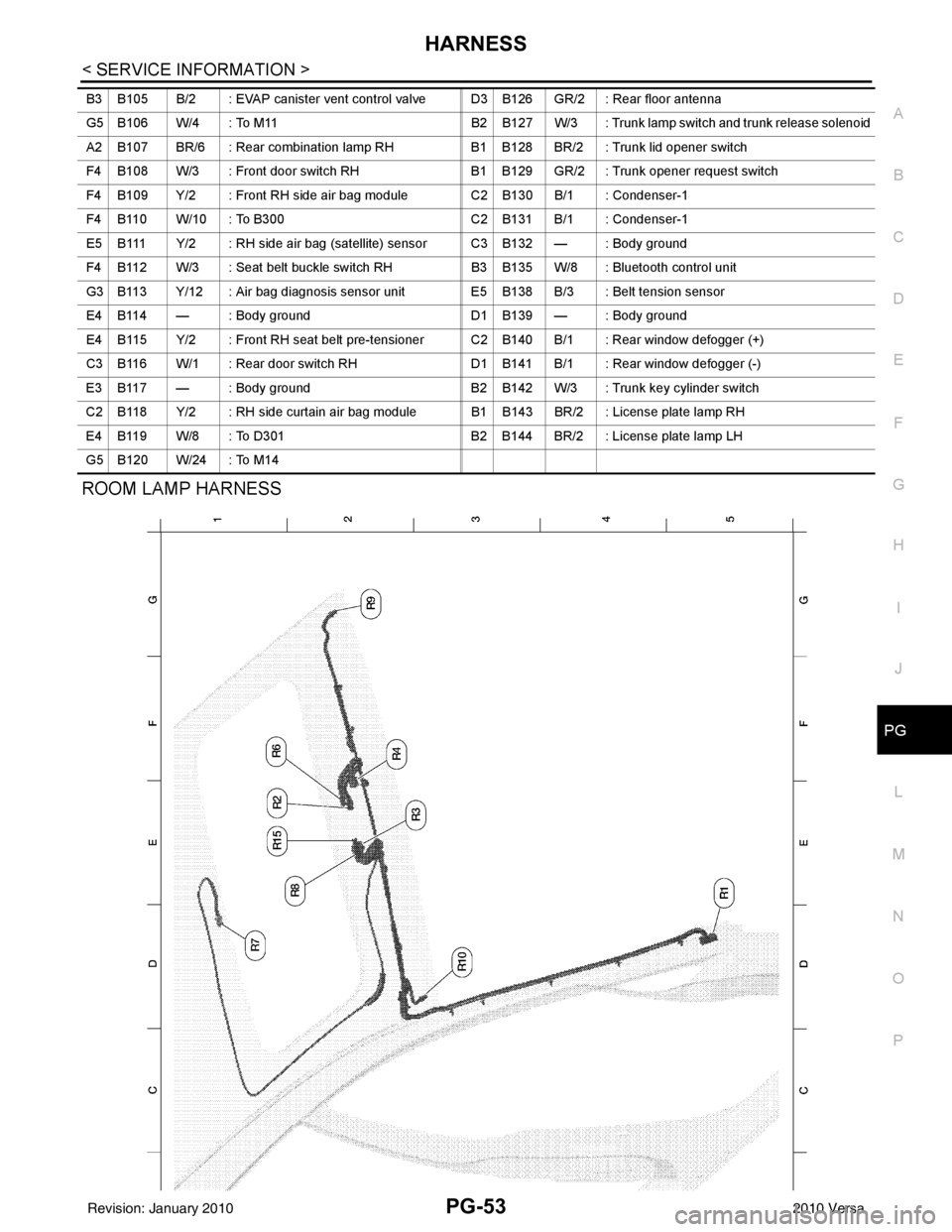
ROOM LAMP HARNESS
B3 B105 B/2 : EVAP canister vent control valve D3 B126 GR/2 : Rear floor antenna
G5 B106 W/4 : To M11 B2 B127 W/3 : Trunk lamp switch and trunk release solenoid
A2 B107 BR/6 : Rear combination lamp RH B1 B128 BR/2 : Trunk lid opener switch
F4 B108 W/3 : Front door switch RH B1 B129 GR/2 : Trunk opener request switch
F4 B109 Y/2 : Front RH side air bag module C2 B130 B/1 : Condenser-1
F4 B110 W/10 : To B300 C2 B131 B/1 : Condenser-1
E5 B111 Y/2 : RH side air bag (satellite) sensor C3 B132 — : Body ground
F4 B112 W/3 : Seat belt buckle switch RH B3 B135 W/8 : Bluetooth control unit
G3 B113 Y/12 : Air bag diagnosis sensor unit E5 B138 B/3 : Belt tension sensor
E4 B114 — : Body ground D1 B139 — : Body ground
E4 B115 Y/2 : Front RH seat belt pre-tensioner C2 B140 B/1 : Rear window defogger (+)
C3 B116 W/1 : Rear door switch RH D1B141 B/1 : Rear window defogger (-)
E3 B117 — : Body ground B2 B142 W/3 : Trunk key cylinder switch
C2 B118 Y/2 : RH side curtain air bag module B1 B143 BR/2 : License plate lamp RH
E4 B119 W/8 : To D301 B2 B144 BR/2 : License plate lamp LH
G5 B120 W/24 : To M14
Revision: January 20102010 Versa
Page 3442 of 3745

HARNESSPG-59
< SERVICE INFORMATION >
C
DE
F
G H
I
J
L
M A
B
PG
N
O P
Wiring Diagram Codes (Cell Codes)INFOID:0000000005395367
Use the chart below to find out what each wiring diagram code stands for.
Refer to the wiring diagram code in the alphabetical index to find the location (page number) of each wiring
diagram.
D4 D405 W/4 : Back door lock assembly C2 D413 B/1 : Rear window defogger (-)
D4 D406 W/2 : Back door request switch F3 D414 — : Body ground
E2 D407 W/2 : High mounted stop lamp
Code Section Wiring Diagram Name
ABS BRC Anti-lock Brake System
A/C,M MTC Manual Air Conditioner
APPS1 EC Accelerator Pedal Position Sensor
A/F EC Air Fuel Ratio Sensor 1
A/FH EC Air Fuel Ratio Sensor 1 Heater
APPS2 EC Accelerator Pedal Position Sensor
APPS3 EC Accelerator Pedal Position Sensor
ASC/BS EC ASCD Brake Switch
ASC/SW EC ASCD Steering Switch
ASCBOF EC ASCD Brake Switch
ASCIND EC ASCD Indicator
AT/IND DI A/T Indicator Lamp
AUDIO AV Audio
BACK/L LT Back-up Lamp
BA/FTS AT A/T Fluid Temperature Sensor and TCM Power Supply
B/DOOR BL Back Door Opener
BRK/SW EC Brake Switch
CAN AT CAN Communication Line
CAN CVT CAN Communication Line
CAN EC CAN Communication Line
CAN LAN CAN System
CHARGE SC Charging System
CHIME DI Warning Chime
COOL/F EC Cooling Fan Control
COMBSW LT Combination Switch
COMM AV Audio Visual Communication System
CVTIND DI CVT Indicator Lamp
D/LOCK BL Power Door Lock
DEF GW Rear Window Defogger
DTRL LT Headlamp - Wi th Daytime Light System
ECTS EC Engine Coolant Temperature Sensor
ENGSS AT Engine Speed Signal
EPS STC Electronic Controlled Power Steering
ETC1 EC Electric Throttle Control Function
ETC2 EC Throttle Control Motor Relay
ETC3 EC Throttle Control Motor
F/FOG LT Front Fog Lamp
F/PUMP EC Fuel Pump
FTS AT A/T Fluid Temperature Sensor
FTS CVT CVT Fluid Temperature Sensor Circuit
FTTS EC Fuel Tank Temperature Sensor
FUEL EC Fuel Ignition System Function
Revision: January 20102010 Versa
Page 3560 of 3745

CHARGING SYSTEMSC-21
< SERVICE INFORMATION >
C
DE
F
G H
I
J
L
M A
B
SC
N
O P
CHARGING SYSTEM
System DescriptionINFOID:0000000005394866
The generator provides DC voltage to operate the vehicl e's electrical system and to keep the battery charged.
The voltage output is controlled by the IC regulator.
Power is supplied at all times to generator terminal 3 through
• 10A fuse (No. 29, located in the fuse and fusible link box).
Power is supplied through terminal 1 to charge the batte ry and operate the vehicle's electrical system. Output
voltage is monitored at terminal 3 by the IC regulator. The charging circuit is protected by the 120A fusible link
[letter a , located in the fusible link box (battery)].
Ground is supplied
• to generator terminal 5
• through body ground F5, and
• through the generator case to the cylinder block
With the ignition switch in the ON or START position, power is supplied
• through 10A fuse [No. 3, located in the fuse block (J/B)]
• to combination meter terminal 28 for the charge warning lamp.
The IC regulator controls ground to terminal 38 of the combination meter through terminal 2 of the generator.
When the ignition is turned on and power becomes availabl e at terminal 2, this "wakes up" the regulator. The
regulator monitors charge output and grounds terminal 2 or leaves it open depending on charge output. With
power and ground supplied, the charge warning lamp will il luminate. When the generator is providing sufficient
voltage, the ground is opened and the charge warning lamp will go off.
If the charge warning lamp illuminates with the engine running, a malfunction is indicated.
Revision: January 20102010 Versa
Page 3563 of 3745
SC-24
< SERVICE INFORMATION >
CHARGING SYSTEM
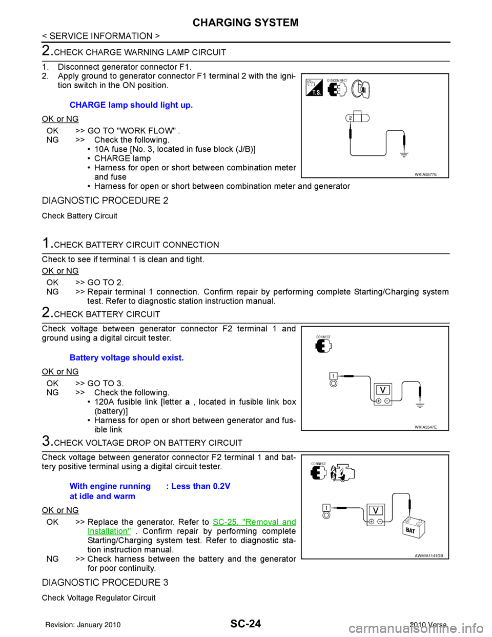
2.CHECK CHARGE WARNING LAMP CIRCUIT
1. Disconnect generator connector F1.
2. Apply ground to generator connector F1 terminal 2 with the igni- tion switch in the ON position.
OK or NG
OK >> GO TO "WORK FLOW" .
NG >> Check the following. • 10A fuse [No. 3, located in fuse block (J/B)]
• CHARGE lamp
• Harness for open or short between combination meterand fuse
• Harness for open or short between combination meter and generator
DIAGNOSTIC PROCEDURE 2
Check Battery Circuit
1.CHECK BATTERY CIRCUIT CONNECTION
Check to see if terminal 1 is clean and tight.
OK or NG
OK >> GO TO 2.
NG >> Repair terminal 1 connection. Confirm repair by performing complete Starting/Charging system test. Refer to diagnostic station instruction manual.
2.CHECK BATTERY CIRCUIT
Check voltage between generator connector F2 terminal 1 and
ground using a digital circuit tester.
OK or NG
OK >> GO TO 3.
NG >> Check the following. • 120A fusible link [letter a , located in fusible link box
(battery)]
• Harness for open or short between generator and fus- ible link
3.CHECK VOLTAGE DROP ON BATTERY CIRCUIT
Check voltage between generator connector F2 terminal 1 and bat-
tery positive terminal using a digital circuit tester.
OK or NG
OK >> Replace the generator. Refer to SC-25, "Removal and
Installation" . Confirm repair by performing complete
Starting/Charging system test. Refer to diagnostic sta-
tion instruction manual.
NG >> Check harness between the battery and the generator for poor continuity.
DIAGNOSTIC PROCEDURE 3
Check Voltage Regulator Circuit
CHARGE lamp should light up.
WKIA5577E
Battery voltage should exist.
WKIA5547E
With engine running
at idle and warm : Less than 0.2V
AWMIA1141GB
Revision: January 20102010 Versa