2010 NISSAN TIIDA Combination switch
[x] Cancel search: Combination switchPage 3016 of 3745
HEADLAMP (FOR USA)LT-21
< SERVICE INFORMATION >
C
DE
F
G H
I
J
L
M A
B
LT
N
O P
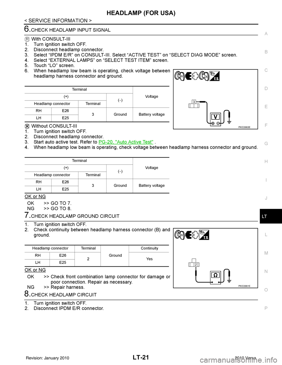
6.CHECK HEADLAMP INPUT SIGNAL
With CONSULT-III
1. Turn ignition switch OFF.
2. Disconnect headlamp connector.
3. Select “IPDM E/R” on CONSUL T-III. Select “ACTIVE TEST” on “SELECT DIAG MODE” screen.
4. Select “EXTERNAL LAMPS” on “SELECT TEST ITEM” screen.
5. Touch “LO” screen.
6. When headlamp low beam is operating, check voltage between
headlamp harness connector and ground.
Without CONSULT-III
1. Turn ignition switch OFF.
2. Disconnect headlamp connector.
3. Start auto active test. Refer to PG-20, "
Auto Active Test" .
4. When headlamp low beam is operating, check voltage between headlamp harness connector and ground.
OK or NG
OK >> GO TO 7.
NG >> GO TO 8.
7.CHECK HEADLAMP GROUND CIRCUIT
1. Turn ignition switch OFF.
2. Check continuity between headlamp harness connector (B) and ground.
OK or NG
OK >> Check front combination lamp connector for damage or poor connection. Repair as necessary.
NG >> Repair harness.
8.CHECK HEADLAMP CIRCUIT
1. Turn ignition switch OFF.
2. Disconnect IPDM E/R connector.
Te r m i n a l
Voltag e
(+)
(−)
Headlamp connector Terminal
RH E26
3Ground Battery voltage
LH E25
Te r m i n a l Voltag e
(+)
(−)
Headlamp connector Terminal
RH E26
3Ground Battery voltage
LH E25
PKIC0963E
Headlamp connector Terminal
Ground Continuity
RH E26 2Yes
LH E25
PKIC0961E
Revision: January 20102010 Versa
Page 3018 of 3745

HEADLAMP (FOR USA)LT-23
< SERVICE INFORMATION >
C
DE
F
G H
I
J
L
M A
B
LT
N
O P
5.CHECK HEADLAMP CIRCUIT
1. Turn ignition switch OFF.
2. Disconnect IPDM E/R connector.
3. Check continuity between IPDM E/R harness connector (A) and headlamp harness connector (B).
OK or NG
OK >> Replace IPDM E/R. Refer to PG-27, "IPDM E/R Power/
Ground Circuit Inspection" .
NG >> Repair harness or connector.
Headlamps Do Not Turn OFFINFOID:0000000005394891
1.CHECK HEADLAMPS TURN OFF
Make sure that lighting switch is OFF. Make sure headlamp turns OFF when ignition switch is turned OFF.
OK or NG
OK >> GO TO 3.
NG >> GO TO 2.
2.CHECK COMBINATION SWITCH INPUT SIGNAL
1. Select “BCM” on CONSULT-III. Select “HEAD LAMP” on “SELECT TEST ITEM” screen.
2. Select “DATA MONITOR” on “SELECT DIAG MODE” screen. Make sure that “HEAD LAMP SW 1” and
“HEAD LAMP SW 2” turns ON-OFF li nked with operation of lighting switch.
OK or NG
OK >> Replace IPDM E/R. Refer to PG-28, "Removal and Installation of IPDM E/R" .
NG >> Check combination switch (lighting switch). Refer to LT-66, "
Combination Switch Inspection" .
3.CHECKING CAN COMMUNICATIONS BETWEEN BCM AND IPDM E/R
Select “BCM” on CONSULT-III, and perform self-diagnosis for “BCM”.
Display of self
-diagnosis results
NO DTC>> Replace IPDM E/R. Refer to PG-28, "Removal and Installation of IPDM E/R".
CAN COMM CIRCUIT>> Refer to LAN-7, "
System Description".
CircuitAB
Continuity
Connector Terminal Connector Terminal
RH E47 54 E26
3Yes
LH 52 E25
WKIA5471E
When lighting switch is OFF
position : HEAD LAMP SW 1 OFF
: HEAD LAMP SW 2 OFF
Revision: January 20102010 Versa
Page 3023 of 3745
LT-28
< SERVICE INFORMATION >
HEADLAMP (FOR CANADA) - DAYTIME LIGHT SYSTEM -
HEADLAMP (FOR CANADA) - DAYTIME LIGHT SYSTEM -
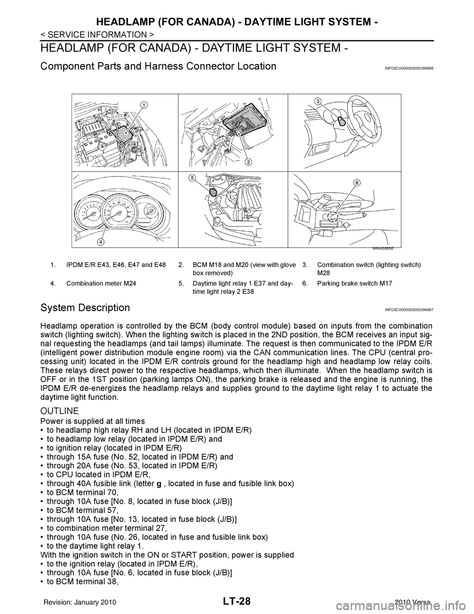
Component Parts and Harness Connector LocationINFOID:0000000005394896
System DescriptionINFOID:0000000005394897
Headlamp operation is controlled by the BCM (body c ontrol module) based on inputs from the combination
switch (lighting switch). When the lighting switch is pl aced in the 2ND position, the BCM receives an input sig-
nal requesting the headlamps (and tail lamps) illuminate. The request is then communicated to the IPDM E/R
(intelligent power distribution module engine room) vi a the CAN communication lines. The CPU (central pro-
cessing unit) located in the IPDM E/R controls ground for the headlamp high and headlamp low relay coils.
These relays direct power to the respective headlamps , which then illuminate. When the headlamp switch is
OFF or in the 1ST position (parking lamps ON), the parking brake is released and the engine is running, the
IPDM E/R de-energizes the headlamp relays and supplies ground to the daytime light relay 1 to actuate the
daytime light function.
OUTLINE
Power is supplied at all times
• to headlamp high relay RH and LH (located in IPDM E/R)
• to headlamp low relay (located in IPDM E/R) and
• to ignition relay (located in IPDM E/R)
• through 15A fuse (No. 52, located in IPDM E/R) and
• through 20A fuse (No. 53, located in IPDM E/R)
• to CPU located in IPDM E/R,
• through 40A fusible link (letter g , located in fuse and fusible link box)
• to BCM terminal 70,
• through 10A fuse [No. 8, located in fuse block (J/B)]
• to BCM terminal 57,
• through 10A fuse [No. 13, located in fuse block (J/B)]
• to combination meter terminal 27,
• through 10A fuse (No. 26, located in fuse and fusible link box)
• to the daytime light relay 1.
With the ignition switch in the ON or START position, power is supplied
• to the ignition relay (located in IPDM E/R),
• through 10A fuse [No. 6, located in fuse block (J/B)]
• to BCM terminal 38,
1. IPDM E/R E43, E46, E47 and E48 2. BCM M18 and M20 (view with glove
box removed)3. Combination switch (lighting switch)
M28
4. Combination meter M24 5. Daytime light relay 1 E37 and day-
time light relay 2 E38 6. Parking brake switch M17
WKIA5555E
Revision: January 20102010 Versa
Page 3024 of 3745
![NISSAN TIIDA 2010 Service Repair Manual HEADLAMP (FOR CANADA) - DAYTIME LIGHT SYSTEM -
LT-29
< SERVICE INFORMATION >
C
D E
F
G H
I
J
L
M A
B
LT
N
O P
• through 10A fuse [No. 3, located in fuse block (J/B)]
• to combination meter termina](/manual-img/5/57397/w960_57397-3023.png "NISSAN TIIDA 2010 Service Repair Manual HEADLAMP (FOR CANADA) - DAYTIME LIGHT SYSTEM -
LT-29
< SERVICE INFORMATION >
C
D E
F
G H
I
J
L
M A
B
LT
N
O P
• through 10A fuse [No. 3, located in fuse block (J/B)]
• to combination meter termina")
HEADLAMP (FOR CANADA) - DAYTIME LIGHT SYSTEM -
LT-29
< SERVICE INFORMATION >
C
D E
F
G H
I
J
L
M A
B
LT
N
O P
• through 10A fuse [No. 3, located in fuse block (J/B)]
• to combination meter terminal 28.
With the ignition switch in the ACC or ON position, power is supplied
• through 10A fuse [No. 20, located in fuse block (J/B)]
• to BCM terminal 11.
Ground is supplied
• to BCM terminal 67 and
• to combination meter terminals 21, 22 and 23
• through grounds M57 and M61,
• to IPDM E/R terminals 39 and 59
• through grounds E15 and E24,
HEADLAMP OPERATION
Low Beam Operation
With the lighting switch in 2ND position, the BCM re ceives an input signal requesting the headlamps to illumi-
nate. This input signal is communicated to the IPDM E/R via the CAN communication lines. The CPU located
in the IPDM E/R controls the headlamp low relay coil, which when energized, directs power
• through 15A fuse (No. 41, located in IPDM E/R)
• through IPDM E/R terminal 54
• to daytime light relay 2 terminals 1 and 5 (energizing the relay),
• through daytime light relay 2 terminal 3
• to front combination lamp RH terminal 3, and
• through 15A fuse (No. 40, located in IPDM E/R)
• through IPDM E/R terminal 52
• to front combination lamp LH terminal 3.
Ground is supplied
• to front combination lamp LH terminal 2
• through grounds E15 and E24,
• to headlamp RH terminal 2 via
• daytime light relay 1 terminals 3 and 4
• through grounds E15 and E24.
With power and ground supplied, low beam headlamps illuminate.
High Beam/Flash-to-Pass Operation
With the lighting switch in 2ND position and high beam s witch in the HIGH position, the BCM receives input
signal requesting the headlamp high beams to illuminate. The flash-to-pass feature can be used any time and
also sends a signal to the BCM. This input signal is communicated to the IPDM E/R and the combination
meter via the CAN communication lines. The CPU locat ed in the IPDM E/R controls the headlamp high relay
coil, which when energized, directs power
• through 10A fuse (No. 34, located in IPDM E/R)
• through IPDM E/R terminal 56
• to front combination lamp RH terminal 1, and
• through 10A fuse (No. 35, located in IPDM E/R)
• through IPDM E/R terminal 55
• to front combination lamp LH terminal 1.
Ground is supplied
• to front combination lamp LH terminal 2
• through grounds E15 and E24, and
• to front combination lamp RH terminal 2 via
• daytime light relay 1 terminals 3 and 4
• through grounds E15 and E24.
With power and ground supplied, the high beam headlamps illuminate.
The BCM sends a signal to the combination meter requesting the high beam indicator lamp to turn ON.
Daytime Light System Operation
With the lighting switch in the OFF or 1ST position (parking lamps ON), the BCM receives inputs requesting
the headlights off. If the parking brake is released and the engine is running, the BCM then sends a signal, via
the CAN communication lines, requesting the IPDM E/R to activate the daytime light system. The CPU located
in the IPDM E/R controls the daytime light relay 1 coil, which when energized, directs power
• from daytime light relay 1 terminal 3
• to front combination lamp RH terminal 2,
• through front combination lamp RH high beam terminal 1
Revision: January 20102010 Versa
Page 3025 of 3745
LT-30
< SERVICE INFORMATION >
HEADLAMP (FOR CANADA) - DAYTIME LIGHT SYSTEM -
• to IPDM E/R terminal 56,
• through 10A fuse (No. 34, located in IPDM E/R) and
• through both de-energized headlamp high relays
• to 10A fuse (No. 35, located in IPDM E/R),
• through IPDM E/R terminal 55
• to front combination lamp LH terminal high beam 1.
Ground is supplied
• to front combination lamp LH terminal 2
• through grounds E15 and E24,
• to daytime light relay 1 terminal 1
• through IPDM E/R terminal 6.
With power and ground supplied, high beam headlamps illuminate at reduced intensity.
COMBINATION SWITCH READING FUNCTION
Refer to BCS-4, "System Description" .
EXTERIOR LAMP BATTERY SAVER CONTROL
Refer to LT-75, "System Description" .
CAN Communication System DescriptionINFOID:0000000005394898
Refer to LAN-7, "System Description" .
Revision: January 20102010 Versa
Page 3037 of 3745
LT-42
< SERVICE INFORMATION >
FRONT FOG LAMP
FRONT FOG LAMP
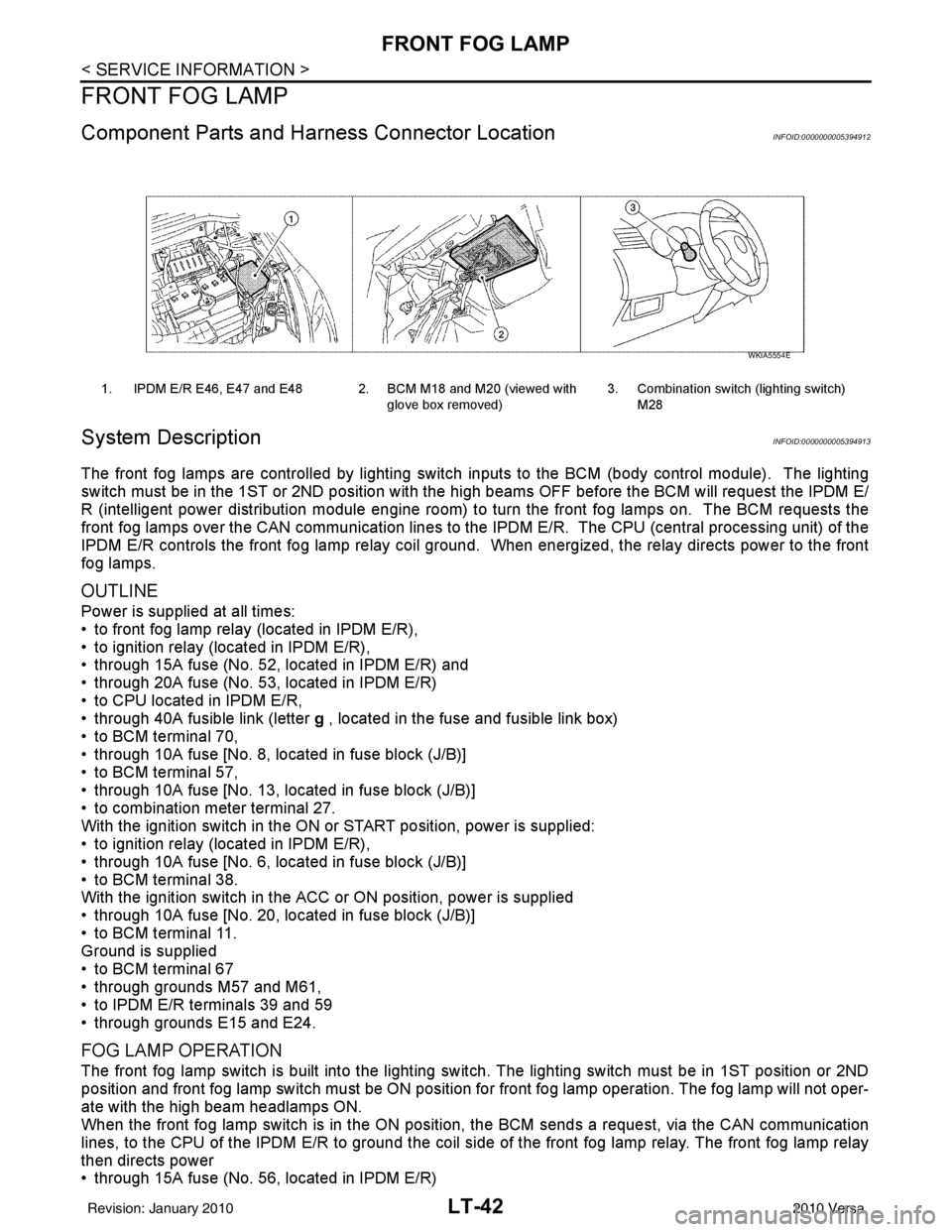
Component Parts and Harness Connector LocationINFOID:0000000005394912
System DescriptionINFOID:0000000005394913
The front fog lamps are controlled by lighting switch inputs to the BCM (body control module). The lighting
switch must be in the 1ST or 2ND position with t he high beams OFF before the BCM will request the IPDM E/
R (intelligent power distribution module engine room) to turn the front fog lamps on. The BCM requests the
front fog lamps over the CAN communication lines to the IPDM E/R. The CPU (central processing unit) of the
IPDM E/R controls the front fog lamp relay coil ground. When energized, the relay directs power to the front
fog lamps.
OUTLINE
Power is supplied at all times:
• to front fog lamp relay (located in IPDM E/R),
• to ignition relay (located in IPDM E/R),
• through 15A fuse (No. 52, located in IPDM E/R) and
• through 20A fuse (No. 53, located in IPDM E/R)
• to CPU located in IPDM E/R,
• through 40A fusible link (letter g , located in the fuse and fusible link box)
• to BCM terminal 70,
• through 10A fuse [No. 8, located in fuse block (J/B)]
• to BCM terminal 57,
• through 10A fuse [No. 13, located in fuse block (J/B)]
• to combination meter terminal 27.
With the ignition switch in the ON or START position, power is supplied:
• to ignition relay (located in IPDM E/R),
• through 10A fuse [No. 6, located in fuse block (J/B)]
• to BCM terminal 38.
With the ignition switch in the ACC or ON position, power is supplied
• through 10A fuse [No. 20, located in fuse block (J/B)]
• to BCM terminal 11.
Ground is supplied
• to BCM terminal 67
• through grounds M57 and M61,
• to IPDM E/R terminals 39 and 59
• through grounds E15 and E24.
FOG LAMP OPERATION
The front fog lamp switch is built into the lighting s witch. The lighting switch must be in 1ST position or 2ND
position and front fog lamp switch must be ON position fo r front fog lamp operation. The fog lamp will not oper-
ate with the high beam headlamps ON.
When the front fog lamp switch is in the ON positi on, the BCM sends a request, via the CAN communication
lines, to the CPU of the IPDM E/R to ground the coil side of the front fog lamp relay. The front fog lamp relay
then directs power
• through 15A fuse (No. 56, located in IPDM E/R)
1. IPDM E/R E46, E47 and E48 2. BCM M18 and M20 (viewed with
glove box removed)3. Combination switch (lighting switch)
M28
WKIA5554E
Revision: January 20102010 Versa
Page 3038 of 3745
FRONT FOG LAMPLT-43
< SERVICE INFORMATION >
C
DE
F
G H
I
J
L
M A
B
LT
N
O P
• through IPDM E/R terminal 50
• to front fog lamp LH terminal 1, and
• through IPDM E/R terminal 51
• to front fog lamp RH terminal 1.
Ground is supplied
• to front fog lamp terminal 2,
• through grounds E15 and E24.
With power and grounds supplied, front fog lamps illuminate.
COMBINATION SWITCH READING FUNCTION
Refer to BCS-4, "System Description" .
EXTERIOR LAMP BATTERY SAVER CONTROL
Refer to LT-75, "System Description" .
CAN Communication System DescriptionINFOID:0000000005394914
Refer to LAN-7, "System Description" .
Revision: January 20102010 Versa
Page 3041 of 3745
LT-46
< SERVICE INFORMATION >
FRONT FOG LAMP
How to Proceed with Trouble Diagnosis
INFOID:0000000005394918
1. Confirm the symptom or customer complaint.
2. Understand operation description and function description. Refer to LT-42, "
System Description" .
3. Perform the Preliminary Check. Refer to LT-46, "
Preliminary Check" .
4. Check symptom and repair or replace the cause of the malfunction.
5. Do the front fog lamps operate normally? If YES, GO TO 6. If NO, GO TO 4.
6. INSPECTION END.
Preliminary CheckINFOID:0000000005394919
CHECK POWER SUPPLY AND GROUND CIRCUIT FOR BCM
Refer to BCS-16, "BCM Power Supply and Ground Circuit Inspection" .
CHECK POWER SUPPLY AND GROUND CIRCUIT FOR IPDM E/R
Refer to PG-27, "IPDM E/R Power/Ground Circuit Inspection" .
CONSULT-III Function (BCM)INFOID:0000000005394920
Refer to LT-13, "CONSULT-III Function (BCM)" .
CONSULT-III Function (IPDM E/R)INFOID:0000000005394921
Refer to LT-14, "CONSULT-III Function (IPDM E/R)" .
Front Fog lamps Do Not Illuminate (Both Sides)INFOID:0000000005394922
1.INSPECT FOG LAMP FUSE
Inspect fog lamp 15A fuse No. 56 in IPDM E/R.
OK or NG
OK >> GO TO 2.
NG >> Repair harness.
2.CHECK COMBINATION SWITCH INPUT SIGNAL
1. Select “BCM” on CONSULT-III. Select “HEAD LAMP” on “SELECT TEST ITEM” screen.
2. Select “DATA MONITOR” on “SELECT DIAG MODE” screen. Make sure that “FR FOG SW” turns ON-
OFF linked with operation of fog lamp switch.
With CONSULT-III
Select “BCM” on CONSULT-III. With “HEAD LAMP” dat a monitor, make sure “FR FOG SW” turns ON-OFF
linked with operation of front fog lamp switch.
Without CONSULT-III
Refer to LT-66, "
Combination Switch Inspection" .
OK or NG
OK >> GO TO 3.
NG >> Check combination switch (lighting switch). Refer to LT-66, "
Combination Switch Inspection" .
3.FOG LAMP ACTIVE TEST
With CONSULT-III
1. Select “IPDM E/R” on CONSULT-III. Select “ACTIVE TEST” on “SELECT DIAG MODE” screen.
2. Select “EXTERNAL LAMPS” on “SELECT TEST ITEM” screen.
3. Touch “FOG” screen.
4. Make sure front fog lamp operates.
Without CONSULT-III When fog lamp switch is ON : FR FOG SW ON
Front fog lamp should operate.
Revision: January 20102010 Versa